- •Textbook Series
- •Contents
- •1 Properties of Radio Waves
- •Introduction
- •The Radio Navigation Syllabus
- •Electromagnetic (EM) Radiation
- •Polarization
- •Radio Waves
- •Wavelength
- •Frequency Bands
- •Phase Comparison
- •Practice Frequency (
- •Answers to Practice Frequency (
- •Questions
- •Answers
- •2 Radio Propagation Theory
- •Introduction
- •Factors Affecting Propagation
- •Propagation Paths
- •Non-ionospheric Propagation
- •Ionospheric Propagation
- •Sky Wave
- •HF Communications
- •Propagation Summary
- •Super-refraction
- •Sub-refraction
- •Questions
- •Answers
- •3 Modulation
- •Introduction
- •Keyed Modulation
- •Amplitude Modulation (AM)
- •Single Sideband (SSB)
- •Frequency Modulation (FM)
- •Phase Modulation
- •Pulse Modulation
- •Emission Designators
- •Questions
- •Answers
- •4 Antennae
- •Introduction
- •Basic Principles
- •Aerial Feeders
- •Polar Diagrams
- •Directivity
- •Radar Aerials
- •Modern Radar Antennae
- •Questions
- •Answers
- •5 Doppler Radar Systems
- •Introduction
- •The Doppler Principle
- •Airborne Doppler
- •Janus Array System
- •Doppler Operation
- •Doppler Navigation Systems
- •Questions
- •Answers
- •6 VHF Direction Finder (VDF)
- •Introduction
- •Procedures
- •Principle of Operation
- •Range of VDF
- •Factors Affecting Accuracy
- •Determination of Position
- •VDF Summary
- •Questions
- •Answers
- •7 Automatic Direction Finder (ADF)
- •Introduction
- •Non-directional Beacon (NDB)
- •Principle of Operation
- •Frequencies and Types of NDB
- •Aircraft Equipment
- •Emission Characteristics and Beat Frequency Oscillator (BFO)
- •Presentation of Information
- •Uses of the Non-directional Beacon
- •Plotting ADF Bearings
- •Track Maintenance Using the RBI
- •Homing
- •Tracking Inbound
- •Tracking Outbound
- •Drift Assessment and Regaining Inbound Track
- •Drift Assessment and Outbound Track Maintenance
- •Holding
- •Runway Instrument Approach Procedures
- •Factors Affecting ADF Accuracy
- •Factors Affecting ADF Range
- •Accuracy
- •ADF Summary
- •Questions
- •Answers
- •8 VHF Omni-directional Range (VOR)
- •Introduction
- •The Principle of Operation
- •Terminology
- •Transmission Details
- •Identification
- •Monitoring
- •Types of VOR
- •The Factors Affecting Operational Range of VOR
- •Factors Affecting VOR Beacon Accuracy
- •The Cone of Ambiguity
- •Doppler VOR (DVOR)
- •VOR Airborne Equipment
- •VOR Deviation Indicator
- •Radio Magnetic Indicator (RMI)
- •Questions
- •In-flight Procedures
- •VOR Summary
- •Questions
- •Annex A
- •Annex B
- •Annex C
- •Answers
- •Answers to Page 128
- •9 Instrument Landing System (ILS)
- •Introduction
- •ILS Components
- •ILS Frequencies
- •DME Paired with ILS Channels
- •ILS Identification
- •Marker Beacons
- •Ground Monitoring of ILS Transmissions
- •ILS Coverage
- •ILS Principle of Operation
- •ILS Presentation and Interpretation
- •ILS Categories (ICAO)
- •Errors and Accuracy
- •Factors Affecting Range and Accuracy
- •ILS Approach Chart
- •ILS Calculations
- •ILS Summary
- •Questions
- •Answers
- •10 Microwave Landing System (MLS)
- •Introduction
- •ILS Disadvantages
- •The MLS System
- •Principle of Operation
- •Airborne Equipment
- •Question
- •Answer
- •11 Radar Principles
- •Introduction
- •Types of Pulsed Radars
- •Radar Applications
- •Radar Frequencies
- •Pulse Technique
- •Theoretical Maximum Range
- •Primary Radars
- •The Range of Primary Radar
- •Radar Measurements
- •Radar Resolution
- •Moving Target Indication (MTI)
- •Radar Antennae
- •Questions
- •Answers
- •12 Ground Radar
- •Introduction
- •Area Surveillance Radars (ASR)
- •Terminal Surveillance Area Radars
- •Aerodrome Surveillance Approach Radars
- •Airport Surface Movement Radar (ASMR)
- •Questions
- •Answers
- •13 Airborne Weather Radar
- •Introduction
- •Component Parts
- •AWR Functions
- •Principle of Operation
- •Weather Depiction
- •Control Unit
- •Function Switch
- •Mapping Operation
- •Pre-flight Checks
- •Weather Operation
- •Colour AWR Controls
- •AWR Summary
- •Questions
- •Answers
- •14 Secondary Surveillance Radar (SSR)
- •Introduction
- •Advantages of SSR
- •SSR Display
- •SSR Frequencies and Transmissions
- •Modes
- •Mode C
- •SSR Operating Procedure
- •Special Codes
- •Disadvantages of SSR
- •Mode S
- •Pulses
- •Benefits of Mode S
- •Communication Protocols
- •Levels of Mode S Transponders
- •Downlink Aircraft Parameters (DAPS)
- •Future Expansion of Mode S Surveillance Services
- •SSR Summary
- •Questions
- •Answers
- •15 Distance Measuring Equipment (DME)
- •Introduction
- •Frequencies
- •Uses of DME
- •Principle of Operation
- •Twin Pulses
- •Range Search
- •Beacon Saturation
- •Station Identification
- •VOR/DME Frequency Pairing
- •DME Range Measurement for ILS
- •Range and Coverage
- •Accuracy
- •DME Summary
- •Questions
- •Answers
- •16 Area Navigation Systems (RNAV)
- •Introduction
- •Benefits of RNAV
- •Types and Levels of RNAV
- •A Simple 2D RNAV System
- •Operation of a Simple 2D RNAV System
- •Principle of Operation of a Simple 2D RNAV System
- •Limitations and Accuracy of Simple RNAV Systems
- •Level 4 RNAV Systems
- •Requirements for a 4D RNAV System
- •Control and Display Unit (CDU)
- •Climb
- •Cruise
- •Descent
- •Kalman Filtering
- •Questions
- •Appendix A
- •Answers
- •17 Electronic Flight Information System (EFIS)
- •Introduction
- •EHSI Controller
- •Full Rose VOR Mode
- •Expanded ILS Mode
- •Full Rose ILS Mode
- •Map Mode
- •Plan Mode
- •EHSI Colour Coding
- •EHSI Symbology
- •Questions
- •Appendix A
- •Answers
- •18 Global Navigation Satellite System (GNSS)
- •Introduction
- •Satellite Orbits
- •Position Reference System
- •The GPS Segments
- •The Space Segment
- •The Control Segment
- •The User Segment
- •Principle Of Operation
- •GPS Errors
- •System Accuracy
- •Integrity Monitoring
- •Differential GPS (DGPS)
- •Combined GPS and GLONASS Systems
- •Questions
- •Answers
- •19 Revision Questions
- •Questions
- •Answers
- •Specimen Examination Paper
- •Appendix A
- •Answers to Specimen Examination Paper
- •Explanation of Selected Questions
- •20 Index

AirborneWeather Radar 13
Control Unit
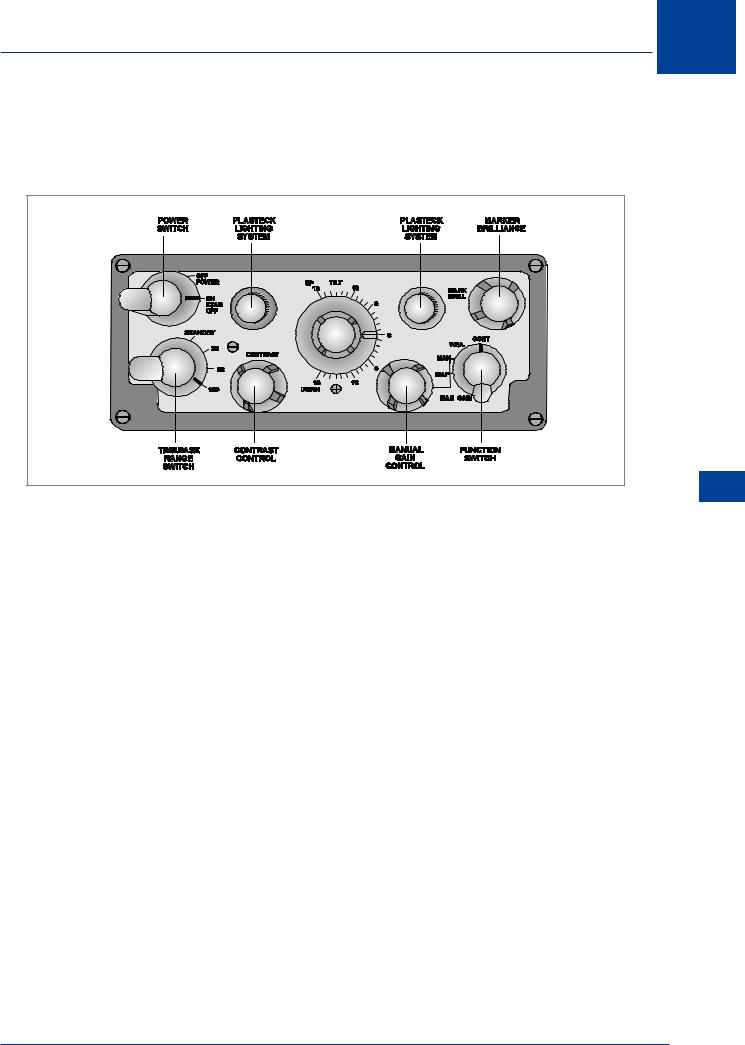
Figure 13.12 illustrates a basic control unit for a monochrome AWR with range scales 20, 50 and 150 NM; its various functions are described below.
Figure 13.12 Control Unit
Power Switch
In the ON position the system is energized and the aerial is automatically stabilized in PITCH and ROLL. A lopsided or asymmetric display probably indicates that the stabilization has failed. Switching to the STAB OFF position will lock the scanner to the pitch and roll axes of the aircraft.
Range Switch
The STANDBY position is to hold the equipment in readiness during periods when the AWR is not required. Selection of a range position energizes the transmitter. Whilst on the ground the STANDBY position must be maintained until it is certain that personnel and any reflecting objects, such as hangars, are not in the radar’s transmitting sector. The radiation can damage health and the reflections from adjacent structures can damage the equipment. Selection of the MAPPING beam produces the same hazards. In poor weather conditions switch from STANDBY to the 0 - 20 NM scale as soon as the aircraft is clear of personnel and buildings and check the weather conditions in the take-off direction. The maximum practical range for weather and for navigation is in the region of 150 NM.
Tilt Control
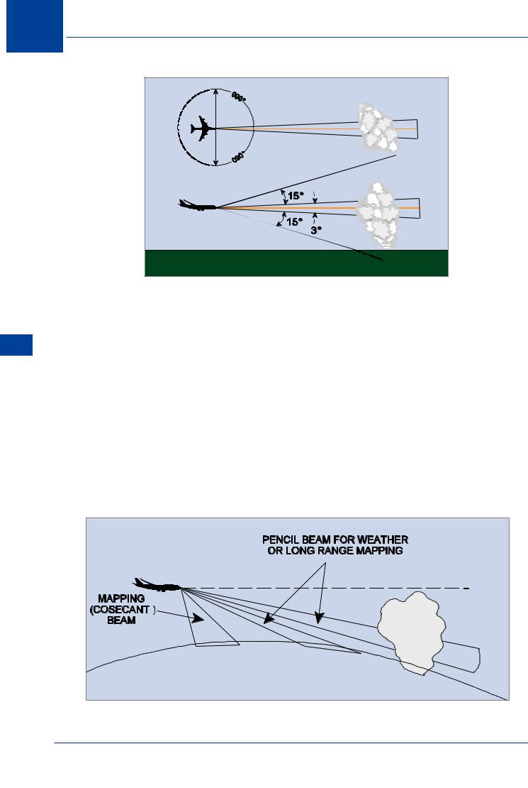
This control enables the radar beam to be tilted from the horizontal within 15° UP (+) and 15° DOWN (-). In the horizontal plane the antenna sweeps up to 90° either side of the nose though a sector of 60° on each side is generally sufficient for the role of weather depiction and navigation. (See Figure 13.13).
For ground mapping the beam has to be tilted down. In order to observe cloud formations it is raised to reduce ground returns. It should be noted that due to the curvature of the earth the tilt should be higher when the selected range increases or when the aircraft descends to a lower altitude. Equally, the tilt setting should be lower when the selected range decreases or when the aircraft climbs to a higher altitude. This can be seen in Figure 13.14.
Airborne Weather Radar 13
215

13 AirborneWeather Radar
Radar Weather Airborne 13
Figure 13.13 Projected Radar Beam and Tilt Angle
Function Switch
MAP
In the MAP position the radar produces a mapping beam. In order to obtain an even presentation of surface features, the transmitted power is progressively reduced as distance decreases so that the power directed to the closest object is minimum. This reduction in power with decreasing range is a function of the cosecant of the depression angle - hence the name cosecant² beam; another description is “fan-shaped” beam. Its dimensions are 85° deep in the vertical plane and 3.5° in azimuth. Signal amplification is adjustable via the adjacent MANUAL GAIN knob.
The minimum (15 NM) and maximum (60 to 70 NM) mapping ranges depend upon the aircraft’s height and type of terrain. To map beyond 70 NM the conical pencil beam should be used by selecting the MANUAL position; this enables the gain to be adjusted, for ground mapping. See Figure 13.15.
2 |
60 - 70 NM |
Figure 13.14 AWR Beam Shapes
216

AirborneWeather Radar
MAN
This is used for cloud detection and mapping between about 70 and 150 NM and selects the conical pencil shaped beam; MANUAL GAIN for signal amplification is operative with this selection.
WEA
This selects the conical pencil beam (Figure 13.14) and is the usual position for observing cloud formations; MANUAL GAIN control is now INOPERATIVE. Instead a facility called Swept Gain, Sensitive Time Control or Automatic Gain Control (AGC) is automatically available. This system of circuits decreases the gain for echoes received from the ever decreasing ranges of clouds. It operates up to about 25 NM and ensures that the intensity (brilliance) of display of a particular cloud is independent of range. Thus a small cloud at 5 NM does not give an increasingly stronger return than a larger and more dangerous cloud at 20 NM; all clouds up to about 25 NM are thus compared on equal terms.
CONT
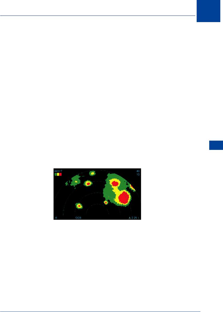
Figure 13.15 is a cloud formation presentation with CONT (CONTOUR) selected for a colour display; the darker colours indicate dangerous areas of concentrated rainfall and potential turbulence.
The degree of danger depends upon the steepness of the rainfall gradient. Therefore, the narrower the paint surrounding a red area, the greater the danger from turbulence; hooks, scalloped edges, finger protrusions and U-shapes are also indicators of potential areas of severe turbulence. The Swept Gain facility (or automatic gain control) is also in operation in the CONT position and ensures that a display’s intensity does not vary as range decreases.
Figure 13.15 Typical cloud display with contour on
13
Airborne Weather Radar 13
217

13 AirborneWeather Radar
Mapping Operation
For the basic monochrome AWR with a maximum range of 150 NM, the cosecant² (fan-shape) beam is used for mapping up to about 70 NM by selecting MAP. To map beyond 70 NM, the pencil beam is used by selecting the MAN position; both have manual gain control in order to improve the radar information obtainable from the presentation.
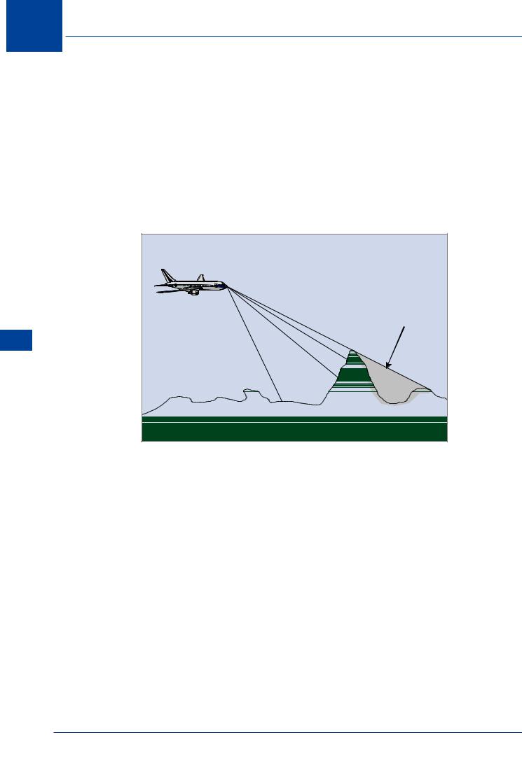
Adjust the downward tilt for the best target presentation. Little energy reflects from a calm sea, fine sand, and flat terrain. Therefore coastlines, built up areas, skyscrapers, bridges and power stations etc. will give very bright returns. Ice has jagged edges which reflect but snow is a poor reflector and masks ground features. Flight over high ground can produce a false image of a series of lakes due to the radar shadow caused by the mountains/hills. (Figure 13.16).
Hill shadow (may give a false impression of water)
Radar Weather Airborne 13
Figure 13.16 Hill Shadow
Pre-flight Checks
Electromagnetic radiation presents a serious hazard to personnel, and electronic equipment, therefore great care must be taken before checking the radar on the ground.
The following precautions should be taken:
•Ensure the aircraft is clear of personnel, other aircraft, vehicles and buildings.
•Select conical beam with maximum uptilt, then switch radar on, check you have a picture, then go back to standby.
218
