
- •Textbook Series
- •Contents
- •1 Properties of Radio Waves
- •Introduction
- •The Radio Navigation Syllabus
- •Electromagnetic (EM) Radiation
- •Polarization
- •Radio Waves
- •Wavelength
- •Frequency Bands
- •Phase Comparison
- •Practice Frequency (
- •Answers to Practice Frequency (
- •Questions
- •Answers
- •2 Radio Propagation Theory
- •Introduction
- •Factors Affecting Propagation
- •Propagation Paths
- •Non-ionospheric Propagation
- •Ionospheric Propagation
- •Sky Wave
- •HF Communications
- •Propagation Summary
- •Super-refraction
- •Sub-refraction
- •Questions
- •Answers
- •3 Modulation
- •Introduction
- •Keyed Modulation
- •Amplitude Modulation (AM)
- •Single Sideband (SSB)
- •Frequency Modulation (FM)
- •Phase Modulation
- •Pulse Modulation
- •Emission Designators
- •Questions
- •Answers
- •4 Antennae
- •Introduction
- •Basic Principles
- •Aerial Feeders
- •Polar Diagrams
- •Directivity
- •Radar Aerials
- •Modern Radar Antennae
- •Questions
- •Answers
- •5 Doppler Radar Systems
- •Introduction
- •The Doppler Principle
- •Airborne Doppler
- •Janus Array System
- •Doppler Operation
- •Doppler Navigation Systems
- •Questions
- •Answers
- •6 VHF Direction Finder (VDF)
- •Introduction
- •Procedures
- •Principle of Operation
- •Range of VDF
- •Factors Affecting Accuracy
- •Determination of Position
- •VDF Summary
- •Questions
- •Answers
- •7 Automatic Direction Finder (ADF)
- •Introduction
- •Non-directional Beacon (NDB)
- •Principle of Operation
- •Frequencies and Types of NDB
- •Aircraft Equipment
- •Emission Characteristics and Beat Frequency Oscillator (BFO)
- •Presentation of Information
- •Uses of the Non-directional Beacon
- •Plotting ADF Bearings
- •Track Maintenance Using the RBI
- •Homing
- •Tracking Inbound
- •Tracking Outbound
- •Drift Assessment and Regaining Inbound Track
- •Drift Assessment and Outbound Track Maintenance
- •Holding
- •Runway Instrument Approach Procedures
- •Factors Affecting ADF Accuracy
- •Factors Affecting ADF Range
- •Accuracy
- •ADF Summary
- •Questions
- •Answers
- •8 VHF Omni-directional Range (VOR)
- •Introduction
- •The Principle of Operation
- •Terminology
- •Transmission Details
- •Identification
- •Monitoring
- •Types of VOR
- •The Factors Affecting Operational Range of VOR
- •Factors Affecting VOR Beacon Accuracy
- •The Cone of Ambiguity
- •Doppler VOR (DVOR)
- •VOR Airborne Equipment
- •VOR Deviation Indicator
- •Radio Magnetic Indicator (RMI)
- •Questions
- •In-flight Procedures
- •VOR Summary
- •Questions
- •Annex A
- •Annex B
- •Annex C
- •Answers
- •Answers to Page 128
- •9 Instrument Landing System (ILS)
- •Introduction
- •ILS Components
- •ILS Frequencies
- •DME Paired with ILS Channels
- •ILS Identification
- •Marker Beacons
- •Ground Monitoring of ILS Transmissions
- •ILS Coverage
- •ILS Principle of Operation
- •ILS Presentation and Interpretation
- •ILS Categories (ICAO)
- •Errors and Accuracy
- •Factors Affecting Range and Accuracy
- •ILS Approach Chart
- •ILS Calculations
- •ILS Summary
- •Questions
- •Answers
- •10 Microwave Landing System (MLS)
- •Introduction
- •ILS Disadvantages
- •The MLS System
- •Principle of Operation
- •Airborne Equipment
- •Question
- •Answer
- •11 Radar Principles
- •Introduction
- •Types of Pulsed Radars
- •Radar Applications
- •Radar Frequencies
- •Pulse Technique
- •Theoretical Maximum Range
- •Primary Radars
- •The Range of Primary Radar
- •Radar Measurements
- •Radar Resolution
- •Moving Target Indication (MTI)
- •Radar Antennae
- •Questions
- •Answers
- •12 Ground Radar
- •Introduction
- •Area Surveillance Radars (ASR)
- •Terminal Surveillance Area Radars
- •Aerodrome Surveillance Approach Radars
- •Airport Surface Movement Radar (ASMR)
- •Questions
- •Answers
- •13 Airborne Weather Radar
- •Introduction
- •Component Parts
- •AWR Functions
- •Principle of Operation
- •Weather Depiction
- •Control Unit
- •Function Switch
- •Mapping Operation
- •Pre-flight Checks
- •Weather Operation
- •Colour AWR Controls
- •AWR Summary
- •Questions
- •Answers
- •14 Secondary Surveillance Radar (SSR)
- •Introduction
- •Advantages of SSR
- •SSR Display
- •SSR Frequencies and Transmissions
- •Modes
- •Mode C
- •SSR Operating Procedure
- •Special Codes
- •Disadvantages of SSR
- •Mode S
- •Pulses
- •Benefits of Mode S
- •Communication Protocols
- •Levels of Mode S Transponders
- •Downlink Aircraft Parameters (DAPS)
- •Future Expansion of Mode S Surveillance Services
- •SSR Summary
- •Questions
- •Answers
- •15 Distance Measuring Equipment (DME)
- •Introduction
- •Frequencies
- •Uses of DME
- •Principle of Operation
- •Twin Pulses
- •Range Search
- •Beacon Saturation
- •Station Identification
- •VOR/DME Frequency Pairing
- •DME Range Measurement for ILS
- •Range and Coverage
- •Accuracy
- •DME Summary
- •Questions
- •Answers
- •16 Area Navigation Systems (RNAV)
- •Introduction
- •Benefits of RNAV
- •Types and Levels of RNAV
- •A Simple 2D RNAV System
- •Operation of a Simple 2D RNAV System
- •Principle of Operation of a Simple 2D RNAV System
- •Limitations and Accuracy of Simple RNAV Systems
- •Level 4 RNAV Systems
- •Requirements for a 4D RNAV System
- •Control and Display Unit (CDU)
- •Climb
- •Cruise
- •Descent
- •Kalman Filtering
- •Questions
- •Appendix A
- •Answers
- •17 Electronic Flight Information System (EFIS)
- •Introduction
- •EHSI Controller
- •Full Rose VOR Mode
- •Expanded ILS Mode
- •Full Rose ILS Mode
- •Map Mode
- •Plan Mode
- •EHSI Colour Coding
- •EHSI Symbology
- •Questions
- •Appendix A
- •Answers
- •18 Global Navigation Satellite System (GNSS)
- •Introduction
- •Satellite Orbits
- •Position Reference System
- •The GPS Segments
- •The Space Segment
- •The Control Segment
- •The User Segment
- •Principle Of Operation
- •GPS Errors
- •System Accuracy
- •Integrity Monitoring
- •Differential GPS (DGPS)
- •Combined GPS and GLONASS Systems
- •Questions
- •Answers
- •19 Revision Questions
- •Questions
- •Answers
- •Specimen Examination Paper
- •Appendix A
- •Answers to Specimen Examination Paper
- •Explanation of Selected Questions
- •20 Index

Chapter
10
Microwave Landing System (MLS)
Introduction |
|
|
|
|
|
|
|
|
|
171 |
ILS Disadvantages |
|
|
|
|
|
|
|
|
|
171 |
The MLS System |
|
|
|
|
|
|
|
|
|
171 |
Principle of Operation . . |
. . . . . . . |
. . |
. . |
. . |
. . |
. . |
. . |
. . |
. . |
. 174 |
Airborne Equipment . . |
. . . . . . . . |
. . |
. . |
. . |
. . |
. . |
. . |
. . |
. . |
.177 |
Question |
|
|
|
|
|
|
|
|
|
179 |
Answer |
|
|
|
|
|
|
|
|
|
180 |
169

10 Microwave Landing System (MLS)
(MLS) System Landing Microwave 10
170

Microwave Landing System (MLS) 10
Introduction
The Microwave Landing System (MLS) was designed to replace ILS with an advanced precision approach system that would overcome the disadvantages of ILS and also provide greater flexibility to its users. However, there are few MLS installations in use at present and they are likely to co-exist with ILS for a long time.
MLS is a precision approach and landing system that provides position information and various ground to air data. The position information is provided in a wide coverage sector and is determined by an azimuth angle measurement, an elevation measurement and a range measurement.
ILS Disadvantages
ILS has the following disadvantages:
• There are only 40 channels available worldwide.
•The azimuth and glide slope beams are fixed and narrow. As a result, aircraft have to be sequenced and adequately separated which causes landing delays.
•There are no special procedures available for slower aircraft, helicopters, and Short Take-off and Landing (STOL) aircraft.
•ILS cannot be sited in hilly areas and it requires large expanses of flat, cleared land to minimize interference with the localizer and glide slope beams.
•Vehicles, taxiing aircraft, low-flying aircraft and buildings have to be kept well away from the transmission sites to minimize localizer and glide slope course deviations (bending of the beams).
The MLS System
The Microwave Landing System (MLS) has the following features:
•There are 200 channels available worldwide.
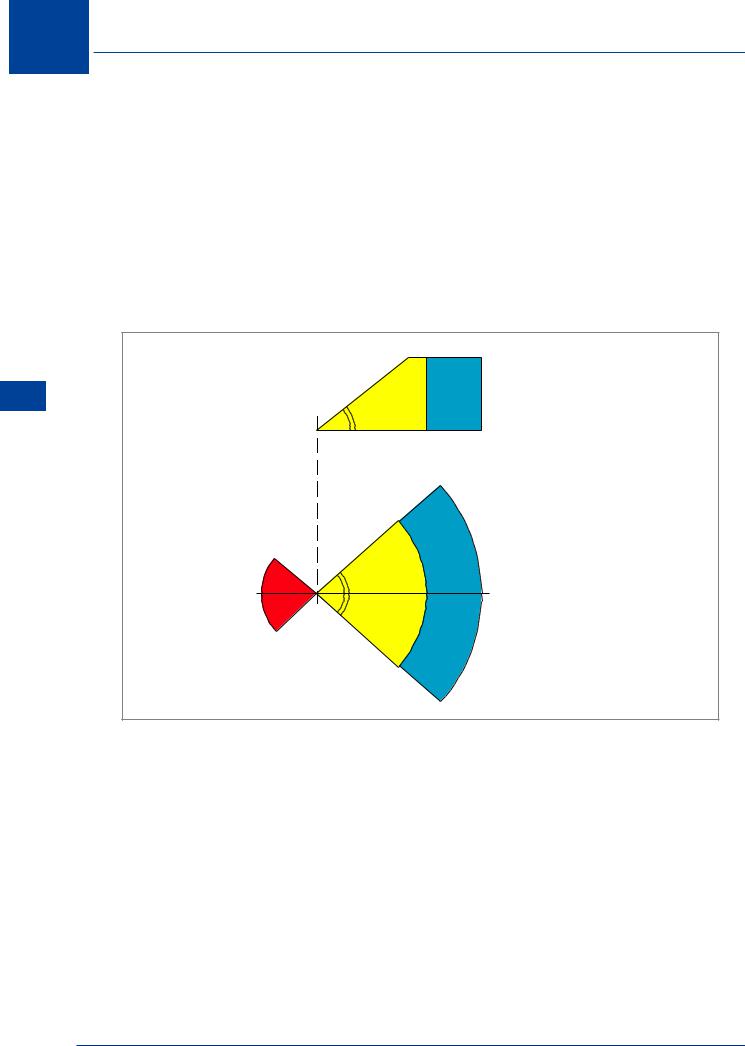
•The azimuth coverage is at least ± 40° of the runway on-course line (QDM) and glide slopes from 0.9° to 20° can be selected. The usable range is 20-30 NM from the MLS site; 20 NM in the UK.
•There is no problem with back course transmissions; a secondary system is provided to give overshoot and departure guidance ± 20° of runway direction up to 15° in elevation to a range of 10 NM and a height of 10 000 ft.
•It operates in the SHF band, 5031 - 5090.7 MHz. This enables it to be sited in hilly areas without having to level the site. Course deviation errors (bending) of the localizer and glide path caused by aircraft, vehicles and buildings are no longer a problem because the MLS scanning beam can be interrupted and therefore avoids the reflections.
•Because of its increased azimuth and elevation coverage aircraft can choose their own approaches. This will increase runway utilization and be beneficial to helicopters and STOL aircraft.
Microwave Landing System (MLS) 10
171

10 Microwave Landing System (MLS)
(MLS) System Landing Microwave 10
•The MLS has a built-in DME.
•MLS is compatible with conventional localizer and glide path instruments, EFIS, auto-pilot systems and area navigation equipment.
•MLS gives positive automatic landing indications plus definite and continuous on/off flag indications for the localizer and glide slope needles.
•The identification prefix for the MLS is an ‘M’ followed by two letters.
•The aim is for all MLS equipped aircraft to operate to CAT III criteria. Figures 10.1, 10.2 and 10.3 below show some of these features.
ELEVATION |
20 000 ft |
|
|
15° |
|
20 |
30 NM |
40° 20 30
40° |
NM |
|
AZIMUTH
Figure 10.1 LMS Coverage
172

Microwave Landing System (MLS) 10
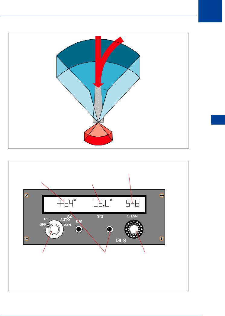
Figure 10.2 Approach Coverage Volume
Channel number, selectable 500 - 699
Approach azimuth (direction) |
Required |
relative to runway centre line. |
glide slope |
AZ |
G /S |
C HAN |
MODE SELECTOR. |
DISPLAY SELECT |
ANGLE/CHANNEL |
|
AUTO: |
Glide slope and azimuth |
PUSHBUTTON. |
SELECTOR. |
|
dictated according to |
Calls up AZ, G/S or CHAN |
Two concentric selectors for |
|
selected channel. |
legend, values of which |
AZ, G/S, CHAN selection |
MAN: |
Preferred G/S and AZ |
are then selected on the |
according to mode on |
|
selections on a given |
ANGLE/CHANNEL |
DISPLAY SELECT |
|
channel may be made. |
SELECTOR |
PUSHBUTTON. |
Figure 10.3 Typical MLS Flight Deck Control Panel
Microwave Landing System (MLS) 10
173