

VHF Omni-directional Range (VOR) 8
Transmitter power, propagation paths and the degree of co-frequency interference protection required, necessitate co-frequency beacons to be separated for planning purposes by an extra 100 NM to about 500 NM. In practice, a beacon is protected as far as is deemed necessary and this is not always the anticipated line of sight reception range.
In the UK this protection is denoted by a DOC, specified as a range and altitude, e.g a DOC of 50/25 published in AIPs means that an aircraft should not experience co-frequency interference within 50 NM of a VOR beacon, up to a height of 25 000 ft. The DOC may also vary by sectors and it is valid day and night. Use of a VOR outside its DOC can lead to navigation errors. Refer to the latest AIC.
Note: When super-refraction conditions exist interference may be experienced within the DOC.
VHF Omni-directional Range (VOR) 8
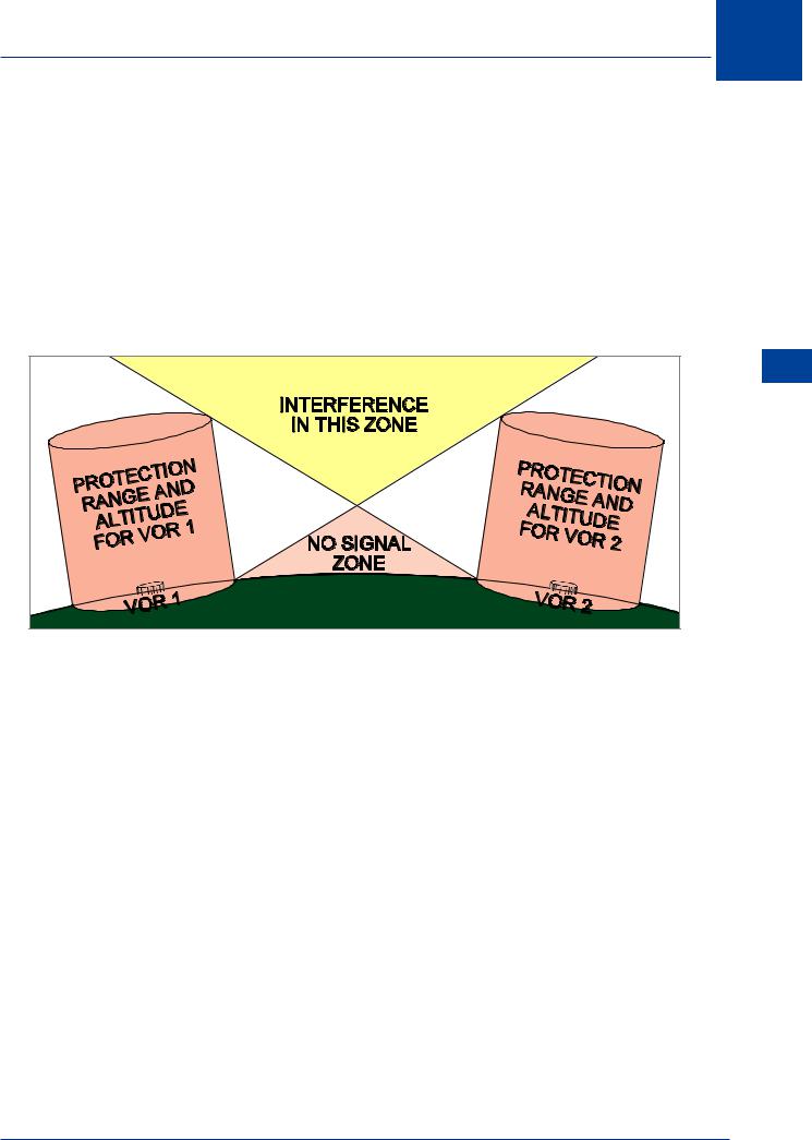
Figure 8.7 Designated Operational Coverage.
VOR 1: DOC 50/25 = No interference within 50 NM range up to 25 000 ft.
VOR 2: DOC 100/50 = No interference within 100 NM range up to 50 000 ft.
Factors Affecting VOR Beacon Accuracy
Site error is caused by uneven terrain such as hills and man-made structures, trees and even long grass, in the vicinity of the transmitter. The error to radiated bearings is termed ‘VOR course-displacement error’. Ground VOR beacon site error is monitored to ± 1° accuracy.
Propagation error is caused by the fact that, having left the VOR site with ±1° accuracy, the transmissions are further affected by terrain and distance. At considerable range from the VOR, ‘bends’ or ‘scalloping’ can occur. VOR scalloping is defined as an imperfection or deviation in the received VOR signal. It causes the signal to 'bend' as a result of reflections from buildings or terrain; it causes the Course Deviation Indicator to slowly or rapidly shift from side to side.
Airborne equipment errors are caused by aircraft equipment assessing and converting the phase differences to 1° of bearing; maximum aircraft equipment error should be ± 3°.
The above errors are aggregated to give a total error of ± 5°. In addition there is pilotage error due to the fact that as an aircraft approaches the VOR the 1° radials get closer together.
117
8 VHF Omni-directional Range (VOR)
(VOR) Range directional-Omni VHF 8
The Cone of Ambiguity
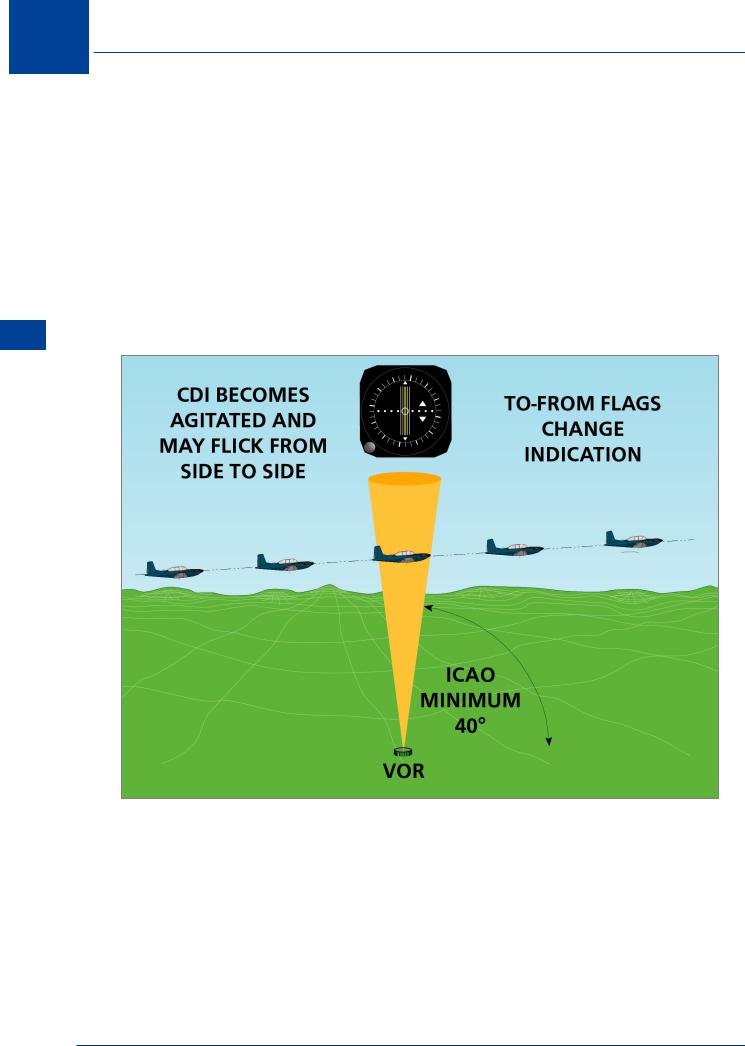
As the VOR is approached, the radials converge and the VOR needle becomes more sensitive. Near the VOR overhead the needle oscillates rapidly and the ‘OFF’ flag may appear momentarily; also the ‘TO/FROM’ display alternates. This is all caused by the cone where there is no planned radiation. This is known as the cone of ambiguity or confusion. Once the aircraft has flown through this cone the readings at the aircraft will stabilize.
Coverage
The VOR shall provide signals to permit satisfactory operation of a typical aircraft installation at the levels and distances required for operational reasons, and up to a minimum elevation angle of 40°. In practice, modern VOR beacons are capable of providing usable signals within 60° to 80° above the horizon.
Figure 8.8 The Cone of Confusion
Doppler VOR (DVOR)
Doppler VORs are second generation VORs. Although their transmission frequencies are the same, the transmitted bearing accuracy is improved as the transmissions are less sensitive to site error.
The transmission differences are:
•The reference signal is AM.
•The variable phase directional signal is FM.
118

VHF Omni-directional Range (VOR) 8
•To maintain the phase relationships which exist in conventional VOR transmissions, the (apparent or simulated) rotation of the directional signal is anti-clockwise. As a result the same airborne VOR equipment can be used with either CVOR or DVOR beacons.
VOR Airborne Equipment
There are 3 main components of the VOR equipment in the aircraft, namely:
•Aerial. For slower aircraft the aerial is a whip type fitted on the fuselage and for high speed aircraft it is a blade type or is flush mounted on either side of the vertical fin.
•Receiver. This is a box fitted in the avionics bay.
•Indicator. Information derived from the VOR signal received at the aircraft may be fed to a flight director system or to the more simple displays such as the CDI (course deviation indicator) or the RMI (radio magnetic indicator). These are described below.
VOR Deviation Indicator
This instrument displays VOR information, and is widely used in light aircraft. The instrument indicates the displacement of the aircraft with respect to a bearing (to or from the VOR station) which has been selected on the Course Selector Knob or OBS (Omni-bearing Selector). See
Figure 8.9.
|
6 |
|
9 |
|
|
|
|
|
|
|
|
|
TO |
15 |
|
|
|
||
0 |
|
|
|
|
|
|
|
|
|
33 |
|
|
|
18 |
|
|
FR |
|
|
|
|
|
|
21 |
OBS |
|
27 |
24 |
|
|
|
|||
|
|
|
|
Figure 8.9 VOR/ILS Deviation Indicator
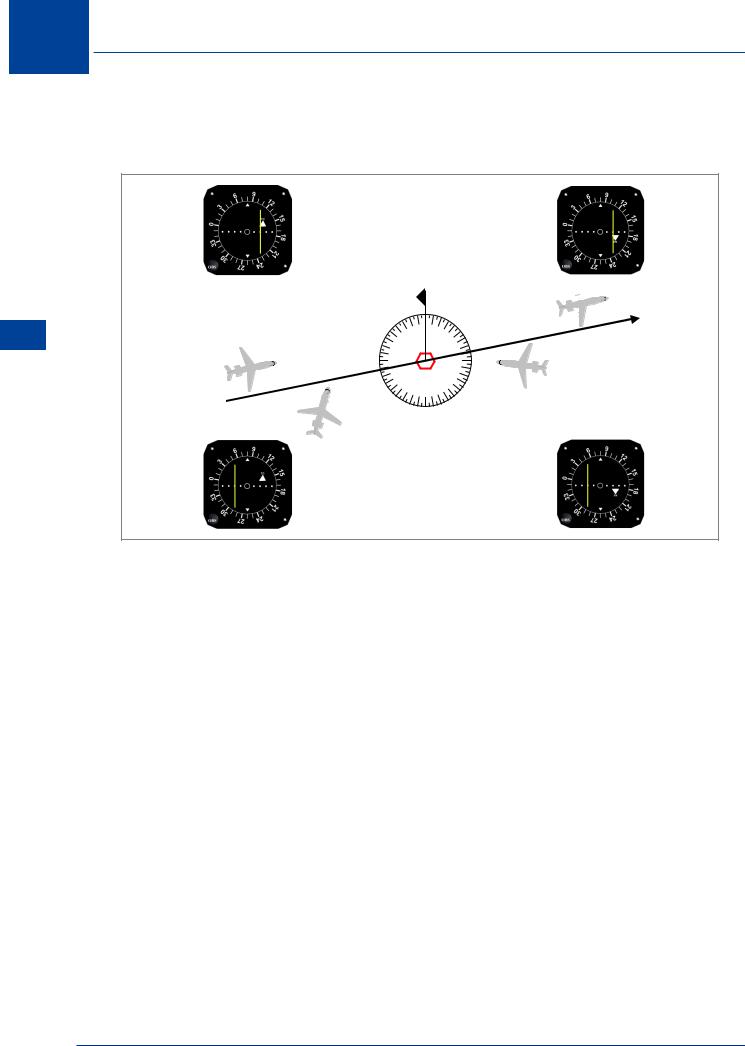
The indicator drawn in Figure 8.10 is typical with the azimuth scale having a circle and four dots on each side of the centre. As the circle itself counts as the first dot this is a five dot display with each dot indicating approximately a 2° displacement from the selected VOR bearing. Full scale deflection therefore represents 10°.
This displacement (or deviation) is presented by a deviation bar on the indicator. Figure 8.10 shows that the displacement of the bar depends on the angular position of the beacon relative to the selected bearing and is independent of the way the aircraft is pointing. In other words, for a given position and bearing selection, the heading of the aircraft does not affect the display on a deviation indicator.
VHF Omni-directional Range (VOR) 8
119
8 VHF Omni-directional Range (VOR)
(VOR) Range directional-Omni VHF 8
Inspection of Figure 8.10 shows that aircraft at positions 1 and 3 receive a Fly Right indication. If the aircraft lay exactly on the selected bearing either to or from the station, the deviation bar would be central.
3 
|
|
0 |
3 |
Course Set 080° |
|
33 |
|
||
|
|
|
||
1 |
30 |
|
6 |
|
|
27 |
|
9 |
|
|
24 |
|
12 |
4 |
|
21 |
18 |
15 |
|
|
|
|
||
|
2 |
|
|
|
|
|
|
|
Figure 8.10 Left/Right Indications
Aircraft at positions 2 and 4 both receive a Fly Left indication (deviation bar to the left of centre) but note that the aircraft at position 4 must turn to the right to reduce its displacement from the selected line. The deviation bar ‘sense’ is wrong for the aircraft at position 4, and this is generally undesirable. To keep the deviation bar sense correct when flying a track to or from a VOR station, the aircraft’s heading should be about the same as the track selected on the Omni-bearing Selector (plus or minus any drift allowance).
As the equipment normally includes an automatic To/From flag the rule to be followed to keep the deviation bar sense correct is that:
When inbound to a VOR, select the inbound track on the OBS, so that a ‘TO’ indication appears. When outbound from a VOR, select the outbound track on the OBS so that a ‘FROM’ indication is seen.
120
VHF Omni-directional Range (VOR) 8
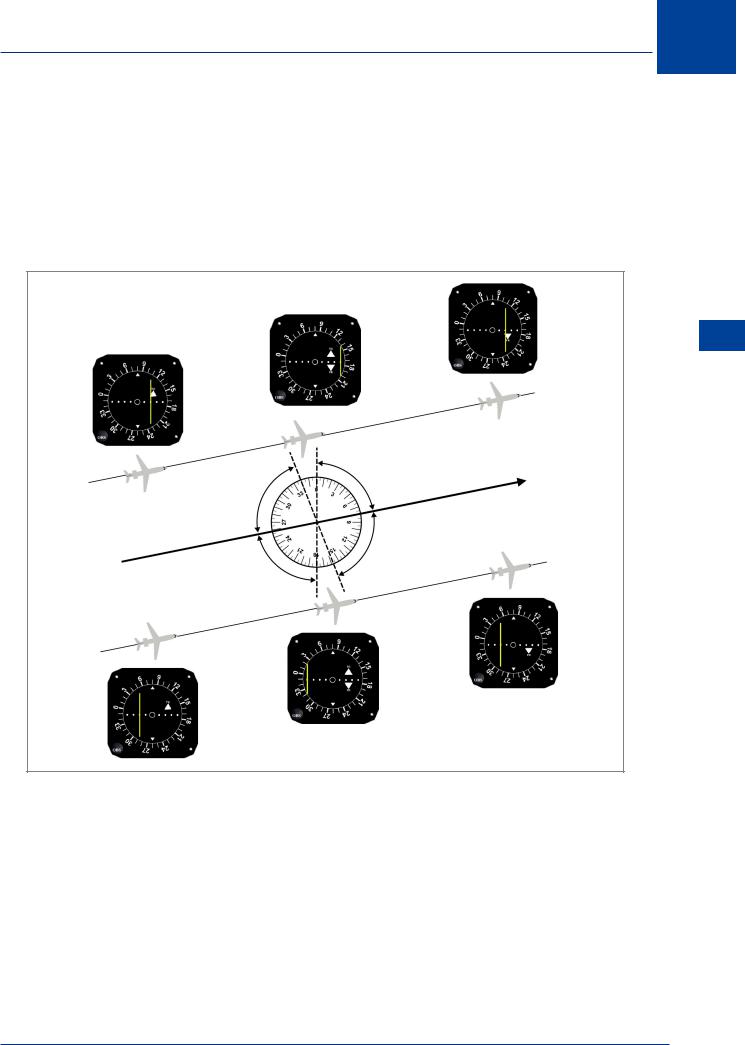
In addition to the Left/Right display, the deviation indicator shows a ‘TO’ or a ‘FROM’ flag depending on whether:
•The aircraft’s QDM is within about 80° of the bearing selected, in which case ‘TO’ appears
•The aircraft’s QDR is within about 80° of the bearing selected, in which case ‘FROM’ appears
This leaves two sectors about 20° wide in which an indeterminate TO/FROM indication is obtained.
VHF Omni-directional Range (VOR) 8
Figure 8.11 To/From Indications
Figure 8.11 depicts the deviation indicator in the various sectors about the VOR beacon. It should be remembered that the six indications in Figure 8.11 are completely independent of the aircraft’s heading. They depend on the aircraft’s bearing from the beacon and on the bearing which has been selected on the OBS.
If the VOR transmissions are faulty or the aircraft is out of range or the airborne power supply is inadequate, an ‘OFF’ flag appears.
121