
- •Textbook Series
- •Contents
- •1 Properties of Radio Waves
- •Introduction
- •The Radio Navigation Syllabus
- •Electromagnetic (EM) Radiation
- •Polarization
- •Radio Waves
- •Wavelength
- •Frequency Bands
- •Phase Comparison
- •Practice Frequency (
- •Answers to Practice Frequency (
- •Questions
- •Answers
- •2 Radio Propagation Theory
- •Introduction
- •Factors Affecting Propagation
- •Propagation Paths
- •Non-ionospheric Propagation
- •Ionospheric Propagation
- •Sky Wave
- •HF Communications
- •Propagation Summary
- •Super-refraction
- •Sub-refraction
- •Questions
- •Answers
- •3 Modulation
- •Introduction
- •Keyed Modulation
- •Amplitude Modulation (AM)
- •Single Sideband (SSB)
- •Frequency Modulation (FM)
- •Phase Modulation
- •Pulse Modulation
- •Emission Designators
- •Questions
- •Answers
- •4 Antennae
- •Introduction
- •Basic Principles
- •Aerial Feeders
- •Polar Diagrams
- •Directivity
- •Radar Aerials
- •Modern Radar Antennae
- •Questions
- •Answers
- •5 Doppler Radar Systems
- •Introduction
- •The Doppler Principle
- •Airborne Doppler
- •Janus Array System
- •Doppler Operation
- •Doppler Navigation Systems
- •Questions
- •Answers
- •6 VHF Direction Finder (VDF)
- •Introduction
- •Procedures
- •Principle of Operation
- •Range of VDF
- •Factors Affecting Accuracy
- •Determination of Position
- •VDF Summary
- •Questions
- •Answers
- •7 Automatic Direction Finder (ADF)
- •Introduction
- •Non-directional Beacon (NDB)
- •Principle of Operation
- •Frequencies and Types of NDB
- •Aircraft Equipment
- •Emission Characteristics and Beat Frequency Oscillator (BFO)
- •Presentation of Information
- •Uses of the Non-directional Beacon
- •Plotting ADF Bearings
- •Track Maintenance Using the RBI
- •Homing
- •Tracking Inbound
- •Tracking Outbound
- •Drift Assessment and Regaining Inbound Track
- •Drift Assessment and Outbound Track Maintenance
- •Holding
- •Runway Instrument Approach Procedures
- •Factors Affecting ADF Accuracy
- •Factors Affecting ADF Range
- •Accuracy
- •ADF Summary
- •Questions
- •Answers
- •8 VHF Omni-directional Range (VOR)
- •Introduction
- •The Principle of Operation
- •Terminology
- •Transmission Details
- •Identification
- •Monitoring
- •Types of VOR
- •The Factors Affecting Operational Range of VOR
- •Factors Affecting VOR Beacon Accuracy
- •The Cone of Ambiguity
- •Doppler VOR (DVOR)
- •VOR Airborne Equipment
- •VOR Deviation Indicator
- •Radio Magnetic Indicator (RMI)
- •Questions
- •In-flight Procedures
- •VOR Summary
- •Questions
- •Annex A
- •Annex B
- •Annex C
- •Answers
- •Answers to Page 128
- •9 Instrument Landing System (ILS)
- •Introduction
- •ILS Components
- •ILS Frequencies
- •DME Paired with ILS Channels
- •ILS Identification
- •Marker Beacons
- •Ground Monitoring of ILS Transmissions
- •ILS Coverage
- •ILS Principle of Operation
- •ILS Presentation and Interpretation
- •ILS Categories (ICAO)
- •Errors and Accuracy
- •Factors Affecting Range and Accuracy
- •ILS Approach Chart
- •ILS Calculations
- •ILS Summary
- •Questions
- •Answers
- •10 Microwave Landing System (MLS)
- •Introduction
- •ILS Disadvantages
- •The MLS System
- •Principle of Operation
- •Airborne Equipment
- •Question
- •Answer
- •11 Radar Principles
- •Introduction
- •Types of Pulsed Radars
- •Radar Applications
- •Radar Frequencies
- •Pulse Technique
- •Theoretical Maximum Range
- •Primary Radars
- •The Range of Primary Radar
- •Radar Measurements
- •Radar Resolution
- •Moving Target Indication (MTI)
- •Radar Antennae
- •Questions
- •Answers
- •12 Ground Radar
- •Introduction
- •Area Surveillance Radars (ASR)
- •Terminal Surveillance Area Radars
- •Aerodrome Surveillance Approach Radars
- •Airport Surface Movement Radar (ASMR)
- •Questions
- •Answers
- •13 Airborne Weather Radar
- •Introduction
- •Component Parts
- •AWR Functions
- •Principle of Operation
- •Weather Depiction
- •Control Unit
- •Function Switch
- •Mapping Operation
- •Pre-flight Checks
- •Weather Operation
- •Colour AWR Controls
- •AWR Summary
- •Questions
- •Answers
- •14 Secondary Surveillance Radar (SSR)
- •Introduction
- •Advantages of SSR
- •SSR Display
- •SSR Frequencies and Transmissions
- •Modes
- •Mode C
- •SSR Operating Procedure
- •Special Codes
- •Disadvantages of SSR
- •Mode S
- •Pulses
- •Benefits of Mode S
- •Communication Protocols
- •Levels of Mode S Transponders
- •Downlink Aircraft Parameters (DAPS)
- •Future Expansion of Mode S Surveillance Services
- •SSR Summary
- •Questions
- •Answers
- •15 Distance Measuring Equipment (DME)
- •Introduction
- •Frequencies
- •Uses of DME
- •Principle of Operation
- •Twin Pulses
- •Range Search
- •Beacon Saturation
- •Station Identification
- •VOR/DME Frequency Pairing
- •DME Range Measurement for ILS
- •Range and Coverage
- •Accuracy
- •DME Summary
- •Questions
- •Answers
- •16 Area Navigation Systems (RNAV)
- •Introduction
- •Benefits of RNAV
- •Types and Levels of RNAV
- •A Simple 2D RNAV System
- •Operation of a Simple 2D RNAV System
- •Principle of Operation of a Simple 2D RNAV System
- •Limitations and Accuracy of Simple RNAV Systems
- •Level 4 RNAV Systems
- •Requirements for a 4D RNAV System
- •Control and Display Unit (CDU)
- •Climb
- •Cruise
- •Descent
- •Kalman Filtering
- •Questions
- •Appendix A
- •Answers
- •17 Electronic Flight Information System (EFIS)
- •Introduction
- •EHSI Controller
- •Full Rose VOR Mode
- •Expanded ILS Mode
- •Full Rose ILS Mode
- •Map Mode
- •Plan Mode
- •EHSI Colour Coding
- •EHSI Symbology
- •Questions
- •Appendix A
- •Answers
- •18 Global Navigation Satellite System (GNSS)
- •Introduction
- •Satellite Orbits
- •Position Reference System
- •The GPS Segments
- •The Space Segment
- •The Control Segment
- •The User Segment
- •Principle Of Operation
- •GPS Errors
- •System Accuracy
- •Integrity Monitoring
- •Differential GPS (DGPS)
- •Combined GPS and GLONASS Systems
- •Questions
- •Answers
- •19 Revision Questions
- •Questions
- •Answers
- •Specimen Examination Paper
- •Appendix A
- •Answers to Specimen Examination Paper
- •Explanation of Selected Questions
- •20 Index

Chapter
8
VHF Omni-directional Range (VOR)
Introduction |
|
|
|
|
|
|
111 |
The Principle of Operation . . . . . . . . . . |
. . |
. . |
. . . . . . |
. . |
. . |
|
.112 |
Terminology |
|
|
|
|
|
|
113 |
Transmission Details |
|
|
|
|
|
|
115 |
Identification . . . . . . . . . . . . . . |
. . |
. . |
. . . . . . |
. . |
. . |
. |
115 |
Monitoring . . . . . . . . . . . . . . . |
. . |
. . |
. . . . . . |
. . |
. . |
. |
115 |
Types of VOR . . . . . . . . . . . . . . |
. . |
. . |
. . . . . . |
. . |
. . |
. |
116 |
The Factors Affecting Operational Range of VOR . |
. . |
. . |
. . . . . . |
. . |
. . |
. |
116 |
Designated Operational Coverage - (DOC) . . . . |
. . |
. . |
. . . . . . |
. . |
. . |
|
.116 |
Factors Affecting VOR Beacon Accuracy |
|
|
|
|
|
|
117 |
The Cone of Ambiguity |
|
|
|
|
|
|
118 |
Doppler VOR (DVOR) |
|
|
|
|
|
|
118 |
VOR Airborne Equipment . . . . . . . . . . |
. . |
. . |
. . . . . . |
. . |
. . |
|
.119 |
VOR Deviation Indicator . . . . . . . . . . |
. . |
. . |
. . . . . . |
. . |
. . |
. |
119 |
Radio Magnetic Indicator (RMI) . . . . . . . . |
. . |
. . |
. . . . . . |
. . |
. . |
|
.122 |
VOR - Displays . . . . . . . . . . . . . . . . . . . . . . . . . . . . . . . . . . . . . . . . . . . .124 |
|||||||
Questions . . . . . . . . . . . . . . . . |
. . |
. . |
. . . . . . |
. . |
. . |
|
.128 |
In-flight Procedures |
|
|
|
|
|
|
129 |
VOR Summary |
|
|
|
|
|
|
132 |
Questions . . . . . . . . . . . . . . . . |
. . |
. . |
. . . . . . |
. . |
. . |
|
.133 |
Annex A . . . . . . . . . . . . . . . . |
. . |
. . |
. . . . . . |
. . |
. . |
. |
141 |
Annex B . . . . . . . . . . . . . . . . |
. . |
. . |
. . . . . . |
. . |
. . |
. |
142 |
Annex C . . . . . . . . . . . . . . . . |
. . |
. . |
. . . . . . |
. . |
. . |
. |
143 |
Answers . . . . . . . . . . . . . . . . |
. . |
. . |
. . . . . . |
. . |
. . |
. |
144 |
Answers to Page 128 . . . . . . . . . . . . |
. . |
. . |
. . . . . . |
. . |
. . |
|
.144 |
109

8 VHF Omni-directional Range (VOR)
(VOR) Range directional-Omni VHF 8
110

VHF Omni-directional Range (VOR) 8
Introduction
8
Figure 8.1 A combined VOR/DME
The VHF Omni-directional Range (VOR) was adopted as the standard short range navigation aid in 1960 by ICAO. It produces bearing information usually aligned with magnetic north at the VOR location. It is practically free from static interference and is not affected by sky waves, which enables it to be used day and night. When the VOR frequency is paired with a co-located Distance Measuring Equipment (DME) an instantaneous range and bearing (Rho-Theta) fix is obtained. The equipment operates within the frequency range of 108 - 117.95 MHz.
VOR has the following uses:
•Marking the beginning, the end and centre line of airways or sections of airways.
•As a let-down aid at airfields using published procedures.
•As a holding point for aircraft.
•As a source of en route navigational position lines.
OMNI-DIRECTIONAL |
SIGNAL |
Figure 8.2 A VOR Polar Diagram
VHF Omni-directional Range (VOR)
111

8 VHF Omni-directional Range (VOR)
(VOR) Range directional-Omni VHF 8
The Principle of Operation
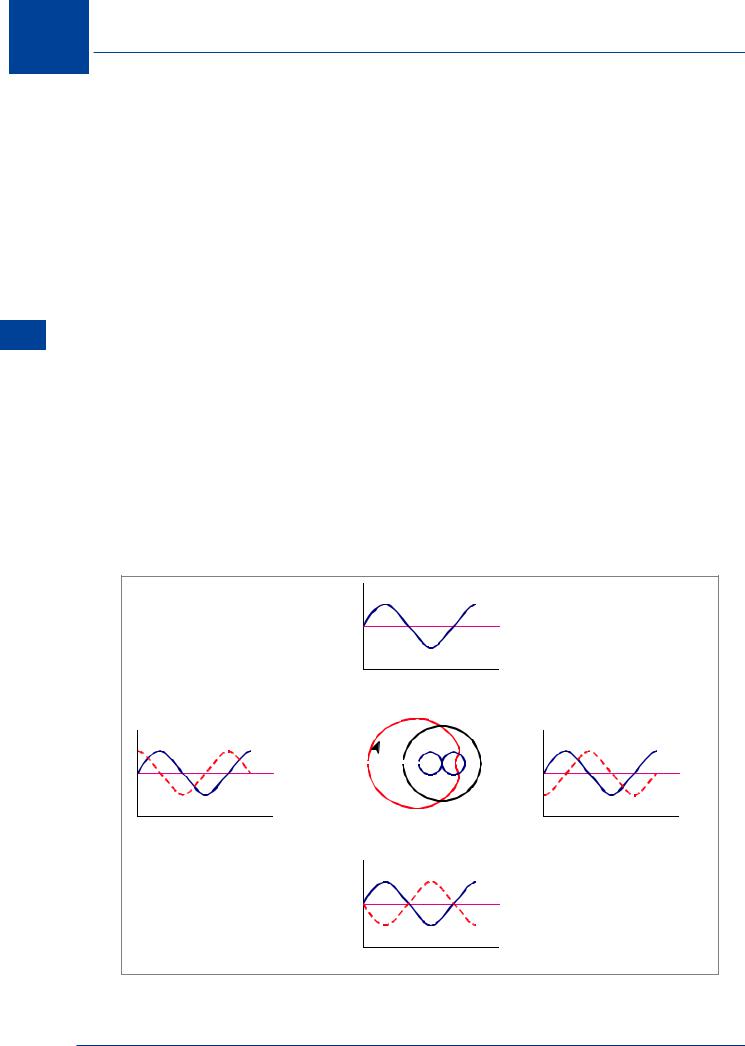
VOR bearing is obtained by phase comparison:
•An aircraft’s VOR receiver measures the phase difference (angular difference) between two signals from the VOR transmitter:
◦◦ a 30 Hz frequency modulated omni-directional, reference signal which produces constant phase regardless of a receiver's bearing from the VOR, and
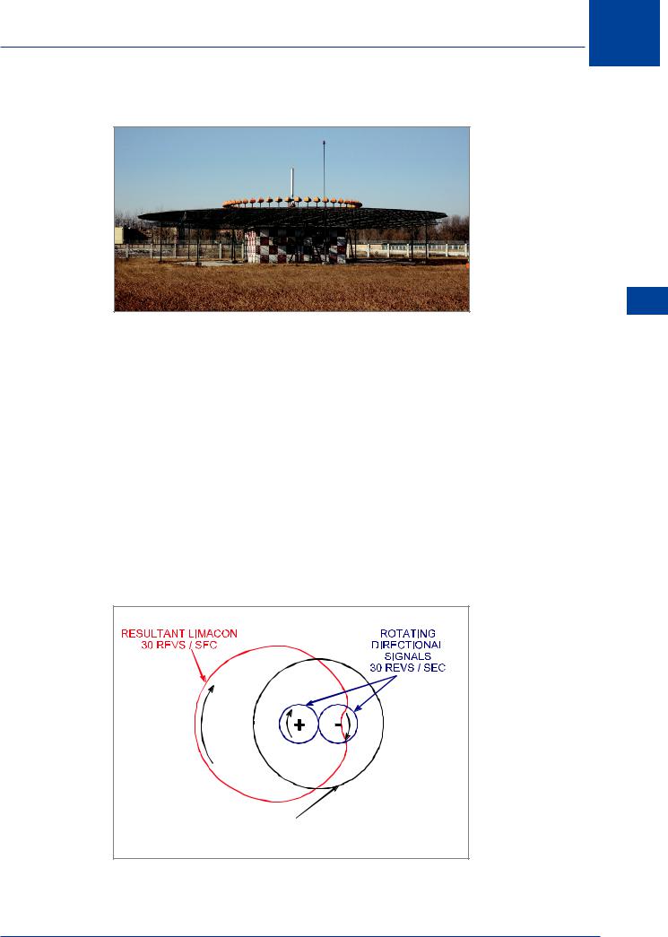
◦◦ a 30 Hz amplitude modulated variable phase (directional) signal created by the rotating transmission pattern (limaçon).
•The 30 Hz FM reference signal is synchronized with the 30 revs/sec rotating directional AM signal (limaçon) such that:
◦◦ the two 30 Hz modulations are in phase to an aircraft’s VOR receiver when it is due magnetic north of the VOR beacon, and
◦◦ the phase difference measured at any other point will equate to the aircraft’s magnetic bearing from the VOR.
The two 30 Hz signals are modulated differently to prevent interaction and merging at the aircraft’s receiver. The rotating limaçon polar diagram, which provides the directional information, is created by combining the polar diagrams of the rotating loop and reference signal. In early VORs the loop rotation was mechanical; modern VORs use electronic circuitry.
Phase Difference 000°
N
Phase Difference 270°
W + -
E
S
Phase Difference 090°
Phase Difference 180°
Figure 8.3 Phase differences corresponding to the cardinal points
112