
- •Textbook Series
- •Contents
- •1 Properties of Radio Waves
- •Introduction
- •The Radio Navigation Syllabus
- •Electromagnetic (EM) Radiation
- •Polarization
- •Radio Waves
- •Wavelength
- •Frequency Bands
- •Phase Comparison
- •Practice Frequency (
- •Answers to Practice Frequency (
- •Questions
- •Answers
- •2 Radio Propagation Theory
- •Introduction
- •Factors Affecting Propagation
- •Propagation Paths
- •Non-ionospheric Propagation
- •Ionospheric Propagation
- •Sky Wave
- •HF Communications
- •Propagation Summary
- •Super-refraction
- •Sub-refraction
- •Questions
- •Answers
- •3 Modulation
- •Introduction
- •Keyed Modulation
- •Amplitude Modulation (AM)
- •Single Sideband (SSB)
- •Frequency Modulation (FM)
- •Phase Modulation
- •Pulse Modulation
- •Emission Designators
- •Questions
- •Answers
- •4 Antennae
- •Introduction
- •Basic Principles
- •Aerial Feeders
- •Polar Diagrams
- •Directivity
- •Radar Aerials
- •Modern Radar Antennae
- •Questions
- •Answers
- •5 Doppler Radar Systems
- •Introduction
- •The Doppler Principle
- •Airborne Doppler
- •Janus Array System
- •Doppler Operation
- •Doppler Navigation Systems
- •Questions
- •Answers
- •6 VHF Direction Finder (VDF)
- •Introduction
- •Procedures
- •Principle of Operation
- •Range of VDF
- •Factors Affecting Accuracy
- •Determination of Position
- •VDF Summary
- •Questions
- •Answers
- •7 Automatic Direction Finder (ADF)
- •Introduction
- •Non-directional Beacon (NDB)
- •Principle of Operation
- •Frequencies and Types of NDB
- •Aircraft Equipment
- •Emission Characteristics and Beat Frequency Oscillator (BFO)
- •Presentation of Information
- •Uses of the Non-directional Beacon
- •Plotting ADF Bearings
- •Track Maintenance Using the RBI
- •Homing
- •Tracking Inbound
- •Tracking Outbound
- •Drift Assessment and Regaining Inbound Track
- •Drift Assessment and Outbound Track Maintenance
- •Holding
- •Runway Instrument Approach Procedures
- •Factors Affecting ADF Accuracy
- •Factors Affecting ADF Range
- •Accuracy
- •ADF Summary
- •Questions
- •Answers
- •8 VHF Omni-directional Range (VOR)
- •Introduction
- •The Principle of Operation
- •Terminology
- •Transmission Details
- •Identification
- •Monitoring
- •Types of VOR
- •The Factors Affecting Operational Range of VOR
- •Factors Affecting VOR Beacon Accuracy
- •The Cone of Ambiguity
- •Doppler VOR (DVOR)
- •VOR Airborne Equipment
- •VOR Deviation Indicator
- •Radio Magnetic Indicator (RMI)
- •Questions
- •In-flight Procedures
- •VOR Summary
- •Questions
- •Annex A
- •Annex B
- •Annex C
- •Answers
- •Answers to Page 128
- •9 Instrument Landing System (ILS)
- •Introduction
- •ILS Components
- •ILS Frequencies
- •DME Paired with ILS Channels
- •ILS Identification
- •Marker Beacons
- •Ground Monitoring of ILS Transmissions
- •ILS Coverage
- •ILS Principle of Operation
- •ILS Presentation and Interpretation
- •ILS Categories (ICAO)
- •Errors and Accuracy
- •Factors Affecting Range and Accuracy
- •ILS Approach Chart
- •ILS Calculations
- •ILS Summary
- •Questions
- •Answers
- •10 Microwave Landing System (MLS)
- •Introduction
- •ILS Disadvantages
- •The MLS System
- •Principle of Operation
- •Airborne Equipment
- •Question
- •Answer
- •11 Radar Principles
- •Introduction
- •Types of Pulsed Radars
- •Radar Applications
- •Radar Frequencies
- •Pulse Technique
- •Theoretical Maximum Range
- •Primary Radars
- •The Range of Primary Radar
- •Radar Measurements
- •Radar Resolution
- •Moving Target Indication (MTI)
- •Radar Antennae
- •Questions
- •Answers
- •12 Ground Radar
- •Introduction
- •Area Surveillance Radars (ASR)
- •Terminal Surveillance Area Radars
- •Aerodrome Surveillance Approach Radars
- •Airport Surface Movement Radar (ASMR)
- •Questions
- •Answers
- •13 Airborne Weather Radar
- •Introduction
- •Component Parts
- •AWR Functions
- •Principle of Operation
- •Weather Depiction
- •Control Unit
- •Function Switch
- •Mapping Operation
- •Pre-flight Checks
- •Weather Operation
- •Colour AWR Controls
- •AWR Summary
- •Questions
- •Answers
- •14 Secondary Surveillance Radar (SSR)
- •Introduction
- •Advantages of SSR
- •SSR Display
- •SSR Frequencies and Transmissions
- •Modes
- •Mode C
- •SSR Operating Procedure
- •Special Codes
- •Disadvantages of SSR
- •Mode S
- •Pulses
- •Benefits of Mode S
- •Communication Protocols
- •Levels of Mode S Transponders
- •Downlink Aircraft Parameters (DAPS)
- •Future Expansion of Mode S Surveillance Services
- •SSR Summary
- •Questions
- •Answers
- •15 Distance Measuring Equipment (DME)
- •Introduction
- •Frequencies
- •Uses of DME
- •Principle of Operation
- •Twin Pulses
- •Range Search
- •Beacon Saturation
- •Station Identification
- •VOR/DME Frequency Pairing
- •DME Range Measurement for ILS
- •Range and Coverage
- •Accuracy
- •DME Summary
- •Questions
- •Answers
- •16 Area Navigation Systems (RNAV)
- •Introduction
- •Benefits of RNAV
- •Types and Levels of RNAV
- •A Simple 2D RNAV System
- •Operation of a Simple 2D RNAV System
- •Principle of Operation of a Simple 2D RNAV System
- •Limitations and Accuracy of Simple RNAV Systems
- •Level 4 RNAV Systems
- •Requirements for a 4D RNAV System
- •Control and Display Unit (CDU)
- •Climb
- •Cruise
- •Descent
- •Kalman Filtering
- •Questions
- •Appendix A
- •Answers
- •17 Electronic Flight Information System (EFIS)
- •Introduction
- •EHSI Controller
- •Full Rose VOR Mode
- •Expanded ILS Mode
- •Full Rose ILS Mode
- •Map Mode
- •Plan Mode
- •EHSI Colour Coding
- •EHSI Symbology
- •Questions
- •Appendix A
- •Answers
- •18 Global Navigation Satellite System (GNSS)
- •Introduction
- •Satellite Orbits
- •Position Reference System
- •The GPS Segments
- •The Space Segment
- •The Control Segment
- •The User Segment
- •Principle Of Operation
- •GPS Errors
- •System Accuracy
- •Integrity Monitoring
- •Differential GPS (DGPS)
- •Combined GPS and GLONASS Systems
- •Questions
- •Answers
- •19 Revision Questions
- •Questions
- •Answers
- •Specimen Examination Paper
- •Appendix A
- •Answers to Specimen Examination Paper
- •Explanation of Selected Questions
- •20 Index

Chapter
7
Automatic Direction Finder (ADF)
Introduction |
|
|
|
85 |
Non-directional Beacon (NDB) |
|
|
|
85 |
Principle of Operation . . . . . . . . . . . . . . . . . . . . . . |
. . |
. . |
|
85 |
Frequencies and Types of NDB |
|
|
|
88 |
Aircraft Equipment . . . . . . . . . . . . . . . . . . . . . . . . |
. . |
. |
|
. 89 |
Emission Characteristics and Beat Frequency Oscillator (BFO) |
|
|
|
89 |
Presentation of Information . . . . . . . . . . . . . . . . . . . . |
. . |
. . |
|
90 |
Uses of the Non-directional Beacon . . . . . . . . . . . . . . . . . . |
. . |
. |
|
. 91 |
Plotting ADF Bearings . . . . . . . . . . . . . . . . . . . . . . |
. . |
. . |
|
91 |
Track Maintenance Using the RBI . . . . . . . . . . . . . . . . . . |
. . |
. . |
|
91 |
Homing . . . . . . . . . . . . . . . . . . . . . . . . . . . . |
. . |
. |
|
. 91 |
Tracking Inbound . . . . . . . . . . . . . . . . . . . . . . . . |
. . |
. . |
|
92 |
Tracking Outbound . . . . . . . . . . . . . . . . . . . . . . . . . . . . . . . . . . . . . . . . . 93 |
||||
Drift Assessment and Regaining Inbound Track . . . . . . . . . . . . . |
. . |
. |
. |
94 |
Drift Assessment and Outbound Track Maintenance |
|
|
|
95 |
Holding . . . . . . . . . . . . . . . . . . . . . . . . . . . . |
. . |
. |
|
. 96 |
Runway Instrument Approach Procedures . . . . . . . . . . . . . . . |
. . |
. |
. |
97 |
Factors Affecting ADF Accuracy . . . . . . . . . . . . . . . . . . . |
. . |
. |
. |
98 |
Factors Affecting ADF Range |
|
|
|
100 |
Accuracy |
|
|
|
101 |
ADF Summary |
|
|
|
101 |
Questions . . . . . . . . . . . . . . . . . . . . . . . . . . . |
. . . .103 |
|||
Answers . . . . . . . . . . . . . . . . . . . . . . . . . . . . |
. . |
. |
|
108 |
83

7 |
|
Automatic Direction Finder (ADF) |
|
||
|
|
|
(ADF) Finder Direction Automatic 7
84

Automatic Direction Finder (ADF) |
|
7 |
|
||
|
|
|
Introduction
Automatic Direction Finder (ADF) equipment in the aircraft is used in conjunction with a simple low and medium frequency non-directional beacon (NDB) on the ground to provide an aid for navigation and for non-precision approaches to airfields. However, it was due to be phased out in 2005, but still continues in use. Indeed, many UK aerodromes still have NDB instrument approach procedures, and it is the only instrument approach procedure available at some aerodromes.
Non-directional Beacon (NDB)
The Non-directional Beacon (NDB) is a ground based transmitter which transmits vertically polarized radio signals, in all directions (hence the name), in the Low Frequency (LF) and Medium Frequency (MF) bands.
When an aircraft’s Automatic Direction Finding (ADF) is tuned to an NDB’s frequency and its call sign identified, the direction of the NDB will be indicated.
A ‘cone of silence’ exists overhead the NDB transmitter during which the aircraft does not receive any signals. The diameter of the cone increases with aircraft height.
Principle of Operation
The ADF measures the bearing of an NDB relative to the fore/aft axis of the aircraft.
If a loop aerial is placed in the plane of the transmitted radio frequency a voltage will be generated in the vertical elements of the loop because of the phase difference of the wave in each of the vertical elements. As the loop is rotated the voltage induced will decrease until it becomes zero when the loop is perpendicular to the radio wave. As the loop continues to rotate a voltage will be induced in the opposite sense etc.
Automatic Direction Finder (ADF) 7
Figure 7.1 A Loop Aerial
85

7 |
|
Automatic Direction Finder (ADF) |
|
||
|
|
|
(ADF) Finder Direction Automatic 7
The polar diagram formed is a figure of eight as shown below (Figure 7.2). It can be seen that there are two null positions and that by rotating the loop until a null is reached the direction of the beacon can be determined. This is fine if the approximate direction of the beacon is known, but if that is not the case then there are two possible choices. Furthermore, if equipment is to automatically determine position, then with only the single loop it would have an insoluble problem.
LOOP |
|
DIPOLE |
|||
|
|
|
|
|
|
|
|
|
|
|
|
|
|
|
|
|
|
|
|
|
|
|
|
|
|
|
|
|
|
NULL
NULL
Figure 7.2 Polar diagrams of loop & dipole aerials
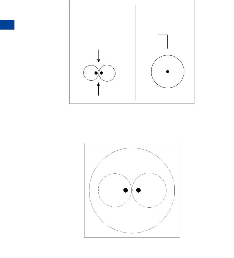
To resolve this ambiguity a simple dipole aerial, called a sense aerial, is added. The polar diagram of the sense aerial is circular. The currents generated are combined electronically as if the sense aerial was in the middle of the loop aerial (Figure 7.3). The relative signal strengths of the two signals are shown.
Figure 7.3
86

Automatic Direction Finder (ADF) |
|
7 |
|
||
|
|
|
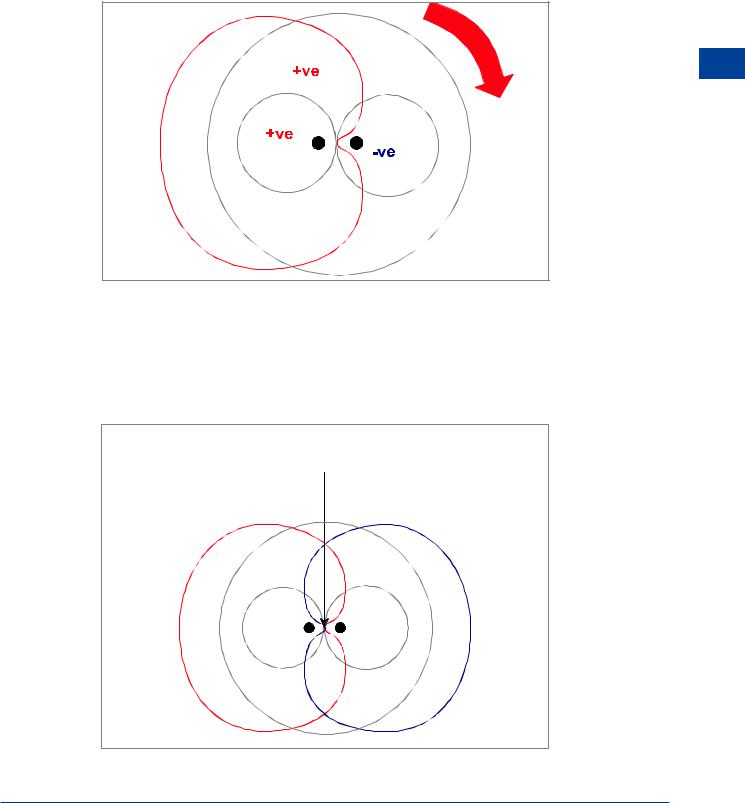
It is arranged for the field from the sense aerial to be in phase with one element (the left hand element shown in diagram) of the loop aerial (Figure 7.4). The resultant polar diagram is known as a CARDIOID. The cardioid has a single null which as can be seen is ill-defined and would not in itself provide an accurate bearing. However, the correct null in the loop aerial can be defined by introducing a logic circuit which defines the correct null as being that null, in the loop aerial which, when the loop aerial is rotated clockwise, produces an increase in signal strength in the cardioid.
Automatic Direction Finder (ADF) 7
Figure 7.4
The resultant null with a single cardioid is not precise enough to meet the ICAO accuracy requirement of +/-5°. To improve the accuracy to meet the requirements, the polarity of the sense aerial is reversed to produce a right hand cardioid. Then by rapidly switching (about 120 Hz) between the two cardioids, the null is more precisely defined and hence the accuracy is improved.
CORRECT
NULL
Figure 7.5
87