

ppl_03_e2
.pdfID: 3658
Customer: Oleg Ostapenko E-mail: ostapenko2002@yahoo.com
Customer: Oleg Ostapenko E-mail: ostapenko2002@yahoo.com
CHAPTER 16: AUTOMATIC DIRECTION FINDING (ADF)
Precipitation Static.
Precipitation static is generated by the collision of water droplets and ice crystals with the aircraft. This phenomenon causes a wandering needle and a background hiss in the audio, and effectively reduces the reception range.
Thunderstorms.
The powerful discharges of static electricity in thunderstorms will cause significant bearing errors in the ADF. For this reason, caution must be exercised when using the ADF in the vicinity of thunderstorms, as the needle can actually point at the thunderstorm.
Night Effect.
At night, the characteristics of the atmosphere change with respect to the transmission of radio waves. Night Effect is most marked around dawn and dusk, and is characterised by needle hunting and audio fade.
Station Interference.
Due to the number of stations in the MF and LF bands, there is the possibility of interference between NDBs which are on or near the same frequency. By day, the DOC will afford protection from interference. By night, interference can be experienced even within the DOC. Identification of an NDB should, therefore, be carried out with particular care at night.
Mountain Effect.
Mountainous areas can cause reflections and diffraction of the transmitted radio waves, leading to errors in ADF systems. These errors will increase at low altitude, so they can be minimised by flying higher.
Coastal Refraction.
Radio waves speed up over water compared to over land. This phenomenon leads to a bending of the waves as they cross the coast, and is the cause of errors in indicated bearings.
Quadrantal Error.
The theoretical polar diagram of the loop aerial is distorted by the airframe which produces a strong electrical field along the fore and aft axis of the aircraft. Incoming NDB signals are, thus, refracted towards the fore and aft airframe axis. This is known as quadrantal error.
Dip Error.
The angle of bank during a turn causes a current to be induced in the horizontal elements of the loop, thereby leading to a bearing error which is referred to as “dip” error. This error is present only when the aircraft is banked, with the ADF needle falling towards the low wing of the aircraft. This error is maximum when the beacon is on the nose/tail axis (typically up to 10º), and at a minimum when the beacon is on the wing axis.
The Absence of Failure Indications in the ADF Display.
Finally, it is important to realise that false indications due to a failure in the ADF system are not readily detectable because of the absence of failure warning within most ADF instruments. Particular care should therefore be exercised in identifying and monitoring the NDB, and independent crosschecks made with other navigational aids where possible.
297

Order: 6026
Customer: Oleg Ostapenko E-mail: ostapenko2002@yahoo.com
Customer: Oleg Ostapenko E-mail: ostapenko2002@yahoo.com
CHAPTER 16: AUTOMATIC DIRECTION FINDING (ADF)
FACTORS AFFECTING ADF RANGE.
The following are the major factors which effect the range of NDB/ADF equipment:
NDB Transmission Power.
Range is proportional to the square of the power output of an NDB. In order to double the range of an NDB, its power output must be increased by a factor of 4.
Precipitation.
All precipitation reduces the effective range and accuracy of ADF bearings.
298

ID: 3658
Customer: Oleg Ostapenko E-mail: ostapenko2002@yahoo.com
Customer: Oleg Ostapenko E-mail: ostapenko2002@yahoo.com
CHAPTER 16: AUTOMATIC DIRECTION FINDING (ADF) QUESTIONS
Representative PPL - type questions to test your theoretical knowledge of Automatic Direction Finding (ADF).
1.Which of the following statements concerning an ADF display fitted with an RBI is true?
a.The display comprises a course deviation indicator and receiver
b.The RBI needle indicates the selected NDB radial
c.The head of the RBI needle indicates the bearing of an NDB relative to the nose of the aircraft
d.The tail of the RBI needle measures the bearing of an NDB relative to the lateral axis of the aircraft
2.Which of the following statements best describes a Non-Directional Beacon (NDB)?
a.A combination of aerials which provides a VOR display with information concerning NDB signals
b.A relative bearing indicator and ADF needle
c.A surface based transmitter which transmits radio signals in all directions
d.A special aerial providing a controller with VDF information
3.Which of the following are items of airborne ADF equipment?
1.Cockpit display
2.Receiver
3.NDB
4.Sense aerial
5.Loop aerial
The correct combination of statements is:
a.1,2,4,5
b.All of the above
c.1,2,3,4
d.1,2,3,5
4.Which of the following phenomena does not affect the accuracy of the ADF?
a.Thunderstorms
b.Precipitation
c.High ground
d.Extensive cloud cover
299

Order: 6026
Customer: Oleg Ostapenko E-mail: ostapenko2002@yahoo.com
Customer: Oleg Ostapenko E-mail: ostapenko2002@yahoo.com
CHAPTER 16: AUTOMATIC DIRECTION FINDING (ADF) QUESTIONS
5.How would a pilot positively identify an NDB to which his ADF equipment is tuned?
a.By the NDB’s morse code indication
b.By the direction in which the ADF needle swings
c.By the movement of the Radio Magnetic Indicator
d.By the accuracy of the QDM
6.An ADF display equipped with a Relative Bearing Indicator indicates 120° when tuned to an NDB located at the pilot’s destination aerodrome. If the aircraft’s Direction Indicator gives the aircraft’s magnetic heading as 090°, what is the QDM to the destination aerodrome?
a.030° (M)
b.120° (M)
c.210° (M)
d.090° (M)
7.An aircraft is heading 150° (M) and wishes to approach its destination aerodrome by flying a QDM of 100° (M) towards an NDB situated on the aerodrome. The aerodrome lies ahead of aircraft and to port, so the pilot is on a reasonably satisfactory heading to intercept the required NDB radial. The pilot, therefore, elects to hold his heading. What will be the indication on his RBI when he intercepts 100° (M) QDM radial?
a.310° (R)
b.050° (R)
c.250° (R)
d.100° (R)
8.If a pilot’s magnetic heading is 170° and his RBI indicates 330° as the relative bearing of an NDB to which his ADF equipment is tuned, what is the QDM to the NDB, and which way must the pilot turn to fly towards the NDB?
a.160° (M)/port
b.140° (M)/port
c.330° (M)/starboard
d.140° (M)/starboard
9.If an ADF display consists of a basic (non-rotatable) RBI, how is the QDM (magnetic bearing) to an NDB determined?
a.Magnetic Heading + QDR
b.Magnetic Heading + Relative Bearing
c.Relative Bearing + True Heading
d.QDM + QDR
300

ID: 3658
Customer: Oleg Ostapenko E-mail: ostapenko2002@yahoo.com
Customer: Oleg Ostapenko E-mail: ostapenko2002@yahoo.com
CHAPTER 16: AUTOMATIC DIRECTION FINDING (ADF) QUESTIONS
10.What is the difference between a basic (non-rotatable) Relative Bearing Indicator (RBI) and a Radio Magnetic Indicator (RMI) in an ADF display?
a.The basic RBI indicates a relative bearing to the NDB, whereas the RMI allows a desired NDB radial to be set with its Omni Bearing Selector
b.The needle of a basic RBI always indicates the QDM to an NDB directly, whereas an RMI requires the indications of the needle to be added to the Magnetic Heading to obtain the QDM
c.The basic RBI indicates a relative bearing which shows the magnetic heading to steer to an NDB, whereas an RMI only indicates the QDR
d.A basic RBI has a compass rose which is fixed in the ADF instrument, with 000° at the 12 o’clock position, while the RMI always indicates the aircraft’s magnetic heading. In both RBI and RMI, the ADF needle always points towards the NDB.
11.What is the difference in the needle indications of an ADF incorporating a basic (non-rotatable) Relative Bearing Indicator (RBI) and an ADF which incorporates a Radio Magnetic Indicator (RMI)?
a.The RBI needle indicates only the relative bearing of the NDB with respect to the nose of the aircraft, whereas the RMI needle gives the QDM directly
b.The RBI needle gives the QDM directly, whereas the RMI indicates the relative bearing of the NDB with respect to the nose of the aircraft
c.The RBI needle gives the magnetic bearing to the NDB directly, whereas the RMI needle indicates the relative bearing of the NDB with respect to the nose of the aircraft
d.The RBI needle always indicates the magnetic heading, whereas the RMI needle is fixed
12.An aircraft is heading 005°(M), as indicated on its DI. The ADF’s RBI indicates a relative bearing of 030° to an NDB to which the pilot has tuned his ADF receiver. What are the QDM and QDR, respectively?
a. |
030° (M) |
210° (M) |
b. |
025° (M) |
205° (M) |
c. |
205° (M) |
025° (M) |
d. |
035° (M) |
215° (M) |
13.An aircraft is heading 200°(M), as indicated on its DI. The ADF’s RBI indicates a relative bearing of 275° to an NDB to which the pilot has tuned his ADF receiver. What are the QDM and QDR, respectively?
a. |
075° (M) |
255° (M) |
b. |
285° (M) |
105° (M) |
c. |
255° (M) |
075° (M) |
d. |
115° (M) |
295° (M) |
301

Order: 6026
Customer: Oleg Ostapenko E-mail: ostapenko2002@yahoo.com
Customer: Oleg Ostapenko E-mail: ostapenko2002@yahoo.com
CHAPTER 16: AUTOMATIC DIRECTION FINDING (ADF) QUESTIONS
14.An aircraft is heading 085°(M), as indicated on its DI. The ADF’s RBI indicates a relative bearing of 040° to an NDB to which the pilot has tuned his ADF receiver. If the local magnetic variation is 3° West, what are the QDM and QTE, respectively?
a. |
125° (M) |
302° (T) |
b. |
045° (M) |
228° (T) |
c. |
040° (M) |
217° (T) |
d. |
125° (M) |
308° (T) |
15.An aircraft is heading 085°(M), as indicated on its DI. The ADF’s RBI indicates a relative bearing of 350° to an NDB to which the pilot has tuned his ADF receiver. If the local magnetic variation is 4° West, what are the QDM and QTE, respectively?
a. |
075° (M) |
|
258° (T) |
|
|
|
|
|
|
|||
b. |
265° (M) |
|
081° (T) |
|
|
|
|
|
|
|||
c. |
075° (M) |
|
251° (T) |
|
|
|
|
|
|
|||
d. |
350° (M) |
|
166° (T) |
|
|
|
|
|
|
|||
|
|
|
|
|
|
|
|
|
|
|
|
|
Question |
1 |
2 |
3 |
4 |
5 |
6 |
7 |
8 |
9 |
10 |
11 |
|
Answer |
|
|
|
|
|
|
|
|
|
|
|
|
|
|
|
|
|
|
|
|
|
|
|
|
|
Question |
12 |
13 |
14 |
15 |
|
|
|
|
|
|
|
|
Answer |
|
|
|
|
|
|
|
|
|
|
|
|
The answers to these questions can be found at the end of this book.
302
Customer: Oleg Ostapenko E-mail: ostapenko2002@yahoo.com
CHAPTER 17
VHF OMNI-DIRECTIONAL RANGE (VOR)
303

Order: 6026
Customer: Oleg Ostapenko E-mail: ostapenko2002@yahoo.com
Customer: Oleg Ostapenko E-mail: ostapenko2002@yahoo.com
CHAPTER 17: VHF OMNI-DIRECTIONAL RANGE (VOR)
304
ID: 3658
Customer: Oleg Ostapenko E-mail: ostapenko2002@yahoo.com
Customer: Oleg Ostapenko E-mail: ostapenko2002@yahoo.com
CHAPTER 17: VHF OMNI-DIRECTIONAL RANGE (VOR)
INTRODUCTION.
The Very High Frequency Omni-directional Range navigation system, known everywhere as VOR, was developed in the United States of America in the 1940s and, in 1960, was adopted by ICAO member states as the standard short range navigation system for aircraft. The VOR is one of the most significant radio-navigation inventions, permitting pilots of all types of aircraft, to navigate easily and accurately from one VOR beacon to another. As far as light aircraft are concerned, and despite the rapidly increasing use of Global Positioning Navigation Systems (GPNS), the VOR remains the primary navigation system.
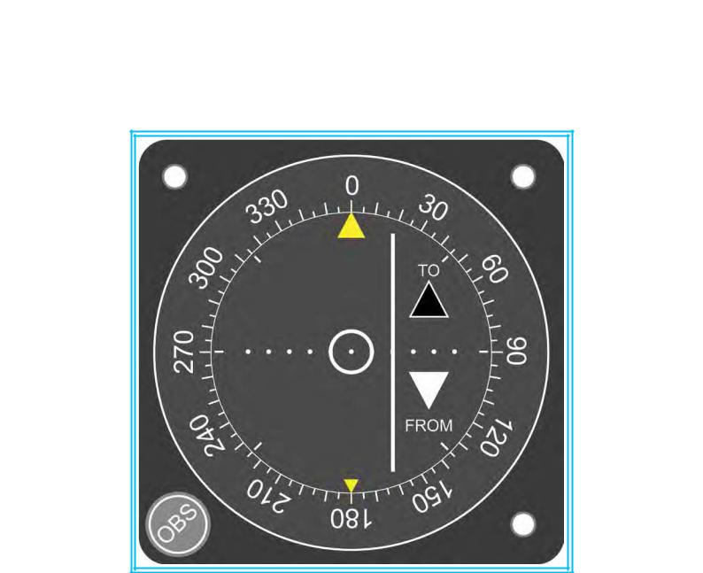
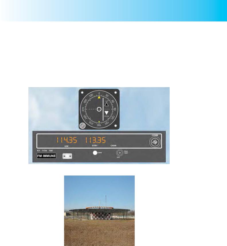
Figure 17.1 VOR Receiver and Display.
Figure 17.2 A VOR Beacon.
Figure 17.1 depicts a typical VOR display and receiver as might be fitted in a light aircraft instrument panel. VOR beacons generally look like the one illustrated in
Figure 17.2.
305
Order: 6026
Customer: Oleg Ostapenko E-mail: ostapenko2002@yahoo.com
Customer: Oleg Ostapenko E-mail: ostapenko2002@yahoo.com
CHAPTER 17: VHF OMNI-DIRECTIONAL RANGE (VOR)
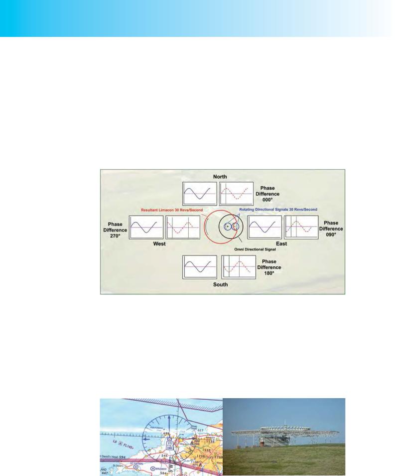
Principle of Operation of the VOR.
The principle of operation of the VOR, illustrated in Figure 17.3, is simple. The VOR beacon transmits two signals at the same time. One signal is a stationary pattern of signals, broadcast in all directions (i.e. omni-directionally), while the other is a rotating pattern of signals. The two signals are in phase on Magnetic North from the VOR beacon; in all other directions there is a phase difference between the two sets of signals which identify the magnetic bearing of the aircraft from the transmitter.
The VOR receiver measures the phase difference between the two signals, and displays it as a bearing on the VOR display. The bearing of the aircraft from the beacon is known as a radial.
VOR beacons transmit in the frequency range 108 Megahertz (MHz) to 117.95 MHz.
Figure 17.3 The two signals from the VOR beacon are in phase on Magnetic North. In all other directions, there is a phase difference between the two sets of signals which identifies the appropriate bearings.
Morse identification codes are also broadcast by VOR transmitters so that pilots can confirm that they are tuned to the desired beacon. Some VORs broadcast voice transmissions containing an Automatic Terminal Information Service (ATIS), giving weather and operational information for a particular airfield; for example, Bovingdon and Biggin VORs both transmit the Heathrow ATIS.
Chart Indication of VOR Stations.
On the ICAO 1:500 000 Chart, locations of VOR beacons are indicated as shown in
Figure 17.4.
Figure 17.4 The Strumble VOR/DME, near Fishguard (Photo by courtesy of Mr Trevor
Diamond.)
306