

ppl_03_e2
.pdfID: 3658
Customer: Oleg Ostapenko E-mail: ostapenko2002@yahoo.com
Customer: Oleg Ostapenko E-mail: ostapenko2002@yahoo.com
CHAPTER 15: VHF DIRECTION FINDING QUESTIONS
Representative PPL - type questions to test your theoretical knowledge of VHF Direction Finding.
1.The accuracy of VHF Direction Finding (VDF) could be affected by:
a.Propagation and site errors
b.Night effect
c.Airframe quadrantal errors
d.Coastal refraction
2.Having received a request for a QDM, the controller responds ‘QDM 080
Class Bravo’. This means the controller has passed:
a.The magnetic bearing of the aircraft from the VDF station, accurate to within +/- 10º
b.The true bearing of the aircraft from the VDF station, accurate to within +/- 10º
c.The magnetic bearing of the VDF station from the aircraft, accurate to within +/- 5º
d.The true bearing of the VDF station from the aircraft, accurate to within +/- 5º
3.On which frequency would you request an emergency VDF positioning service from a D&D Cell?
a.112.5 MHz
b.112.5 KHz
c.121.5 KHz
d.121.5 MHz
4.Which of the following statements is wrong?
a.QDM - magnetic heading TO the station
b.QDR - magnetic bearing FROM the station
c.QTE - true bearing FROM the station
d.QDR - true bearing TO the station
5.Requesting a training fix takes priority over:
a.A Mayday call
b.A pan pan call
c.a practice pan call
d.a distress call
Question |
1 |
2 |
3 |
4 |
5 |
Answer |
|
|
|
|
|
The answers to these questions can be found at the end of this book.
277
Customer: Oleg Ostapenko E-mail: ostapenko2002@yahoo.com
278
Customer: Oleg Ostapenko E-mail: ostapenko2002@yahoo.com
CHAPTER 16
AUTOMATIC DIRECTION
FINDING (ADF)
279

Order: 6026
Customer: Oleg Ostapenko E-mail: ostapenko2002@yahoo.com
Customer: Oleg Ostapenko E-mail: ostapenko2002@yahoo.com
CHAPTER 16: AUTOMATIC DIRECTION FINDING (ADF)
280
ID: 3658
Customer: Oleg Ostapenko E-mail: ostapenko2002@yahoo.com
Customer: Oleg Ostapenko E-mail: ostapenko2002@yahoo.com
CHAPTER 16: AUTOMATIC DIRECTION FINDING (ADF)
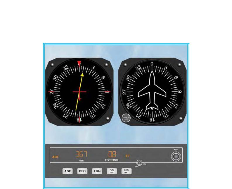
INTRODUCTION.
The simplest type of pilot-interpreted radio-navigation instrument, and one that has been in use since World War 2, is the Automatic Direction Finder (ADF) which is fitted to almost all aircraft. At first glance, the ADF looks like a compass. In fact, the instrument was formerly known as the radio compass. The ADF needle, however, does not indicate Magnetic North, but always points to the beacon to which it is tuned. The beacon in an ADF system is called a Non-Directional Beacon (NDB).
The needle
in an ADF instrument
display
always points in the direction of the NDB to which the ADF equipment is tuned.
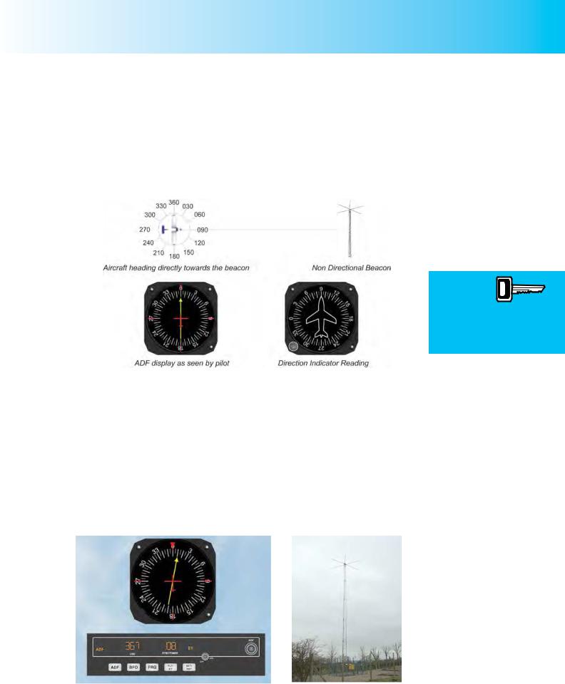
Figure 16.1.
In Figure 16.1, we depict an aircraft flying directly towards the NDB on heading 090°. The pilot, therefore, sees that his Direction Indicator is reading 090° and his ADF needle is in the 12 o’clock position, indicating straight ahead.
The ADF instrument may be thought of, in simple terms, as comprising a needle which points towards the NDB. A pilot, then, whose aircraft is fitted with ADF equipment can tune to and track towards an NDB. If the NDB is located at an airfield, this basic ability of the ADF can be of enormous help to a pilot who is having difficulty in visually locating the airfield.
A Non Directional Beacon (NDB) is a radio transmitter which sends out a radio signal in all directions (Hence, the term “non directional”). The radio signals from NDBs also
Figure 16.2a ADF Receiver and instrument display. |
Figure 16.2b A Non - Directional |
|
Beacon (Photo courtesy of Trevor |
|
Diamond www.trevord.com). |
281

Order: 6026
Customer: Oleg Ostapenko E-mail: ostapenko2002@yahoo.com
Customer: Oleg Ostapenko E-mail: ostapenko2002@yahoo.com
CHAPTER 16: AUTOMATIC DIRECTION FINDING (ADF)
carry a Morse Code signal so that a pilot may identify an individual NDB. Figure 16.2 depicts an ADF instrument display and an NDB.
When a pilot has tuned his ADF equipment to a particular NDB, the pilot may track towards the NDB very much in the same way that an earthbound hiker might follow a compass needle pointing towards Magnetic North. When tracking towards an NDB, the relationship between the NDB and the ADF instrument may be likened to the relationship between Magnetic North and a magnetic compass. Of course, just like using a compass, a pilot may use his ADF to track away from an NDB. However, a hiker trekking away from Magnetic North with the compass needle pointing directly behind him will always be heading 180° (M), whereas a pilot tracking away from an NDB may do so in any specified or non-specified heading, depending on his intentions and instrument fit.
An NDB, then, can “lead” an aircraft tracking towards it, to a position overhead the NDB, from which point the aircraft may either track to another NDB or leave the NDB on any heading selected by the pilot. The pilot may also elect to perform an instrument approach procedure using the NDB for guidance in azimuth, (i.e. in the horizontal plane).
As an alternative to tracking towards or away from an NDB, a pilot may use his ADF equipment to take a bearing from an NDB which provides a position line from the NDB along which the aircraft is situated. A positive position fix can be taken from two NDBs. If the pilot chooses the NDBs judiciously (say, with one of the NDBs being in front of the aircraft, on the nose, and another NDB abeam, port or starboard), a position fix can be taken using one ADF instrument only.
Generally speaking, NDBs in the United Kingdom are either short-range homing devices, or locators for Instrument Landing Systems or for non-precision approaches. The expression “homing” basically means following the indications of the ADF needle until arrival overhead the NDB. As you will discover, homing (without applying drift) can be useful to a pilot but is poor radio-navigation technique, if the aircraft is under the influence of a cross-wind.
The principle of operation of the ADF - NDB system is similar to that of the aerial of a portable radio. If you can recall the phenomenon of the reception of a portable radio varying as you turn the radio set to attempt to increase the strength of the signal, then you have experienced the principle of operation of an ADF - NDB system. With the radio, signal reception is maximised when its aerial is in line with the transmitting station. The ADF works in the same way, but the direction of the NDB can be read off in degrees on the face of the ADF instrument in the cockpit.
THE NON DIRECTIONAL BEACON.
The Automatic Direction Finding system is the oldest of the pilot-interpreted navigation aids currently in use, and its demise has been foretold for decades. Nevertheless, it does have one advantage over the system which followed it, the
VOR (Very High Frequency Omni-Directional Ranging). NDB signals do not operate on the VHF line-of-sight principle but are able to follow the curvature of the Earth, and, thus, can be received at much greater distances and at lower altitudes than are VOR transmitters. (VOR is dealt with in the next chapter.)
However, NDB signals are more affected by atmospheric conditions, mountainous terrain, coastal refraction and electrical storms than are VOR signals, particularly at long range.
282
ID: 3658
Customer: Oleg Ostapenko E-mail: ostapenko2002@yahoo.com
Customer: Oleg Ostapenko E-mail: ostapenko2002@yahoo.com
CHAPTER 16: AUTOMATIC DIRECTION FINDING (ADF)
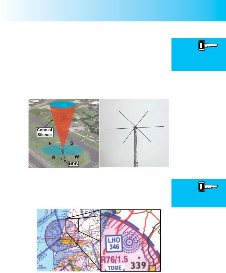
An NDB (Non Directional Beacon) is a ground beacon which emits radio waves in the low and medium frequency range, from 190 kHz to 1750 kHz. The frequencies of most NDBs lie between 250 and 450 kHz.
NDBs used for long range navigation may have useable ranges from 50 nautical miles (nm) to several hundred nautical miles over the oceans. In the United Kingdom, NDBs usually have a range of between 10 and 80 nm. Range depends on the operating power of the NDB transmitter. Low power NDBs are often found on airfields as the locator element in conjunction with an Instrument Landing System. Locators usually have a range of between 10 - 25 nm. The Designated Operational Coverage (DOC) of each NDB in the United Kingdom is published by the United Kingdom Civil Aviation Authority in the UK Aeronautical Information Publication (AIP), En-route (ENR) Section.
Figure 16.3 The Cone of Silence above a Non - Directional Beacon (Photo by courtesy of Trevor Diamond www.trevord.com).
Directly overhead an NDB transmitter, a “cone of silence” exists in which no signal will be received by the aircraft. The diameter of the cone of silence will increase with height above the beacon.
On the 1:500 000 chart, NDB facilities are identified in the manner shown in Figure 16.4, below.
NDBs emit
radio waves in all directions,
within the
frequency range 190 kHz to 1750 kHz. These are low and medium frequency bands.
The required
NDB is identified by
the pilot from
a morse identification code broadcast by the NDB.
Figure 16.4 The NDB located near Le Havre, in France. Its Morse identification is LHO, and its frequency is 346 KHz.
283
Order: 6026
Customer: Oleg Ostapenko E-mail: ostapenko2002@yahoo.com
Customer: Oleg Ostapenko E-mail: ostapenko2002@yahoo.com
CHAPTER 16: AUTOMATIC DIRECTION FINDING (ADF)
The NDB depicted is the one near the airport of Le Havre, in France. The NDB is identified on the chart as LHO 346. LHO is the morse identification code of the NDB, and 346 kHz is its frequency.
AIRCRAFT EQUIPMENT - THE AUTOMATIC DIRECTION FINDER.
Aircraft Automatic Direction Finding (ADF) equipment fitted to the aircraft comprises the following elements:
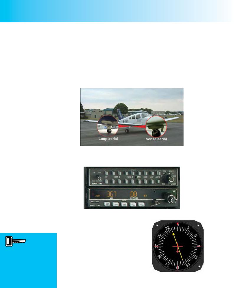
•A loop and sense aerial.
When an ADF display
incorporates a Relative
Bearing Indicator (RBI), with a fixed compass card, 000° on the RBI is always aligned with the nose of the aircraft, being in the 12 o’clock position on the face of the instrument. The compass rose of the RBI does not move automatically.
Figure 16.5 An ADF Loop and Sense Aerial.
•A control unit.
Figure 16.6 A Control Unit and Receiver.
• |
ADF receiver and instrument display. |
|
The pilot-interpreted instrument in the cockpit is |
|
|
likely to be of the type shown in Figure 16.7. This |
|
|
type of ADF display is called a Relative Bearing |
|
|
Indicator (RBI). The compass card on the face |
|
|
of the instrument can be either fixed, with 000° in |
|
|
the 12 o’clock position, aligned with the nose of the |
|
|
aircraft, as shown in Figure 16.7, or the compass |
|
|
card can be manually rotated by turning a knob |
|
|
on the instrument, in which case the instrument is |
|
|
known as a Relative Bearing Selector (RBS). With |
Figure 16.7 An ADF Display, |
|
an RBI such as that depicted by Figure 16.7, the |
incorporating a Relative Bearing |
|
head of the needle always indicates the relative |
Indicator (RBI). |
|
bearing of the NDB with respect to the aircraft’s |
|
|
heading. |
|
|
284

ID: 3658
Customer: Oleg Ostapenko E-mail: ostapenko2002@yahoo.com
Customer: Oleg Ostapenko E-mail: ostapenko2002@yahoo.com
CHAPTER 16: AUTOMATIC DIRECTION FINDING (ADF)
The Receiver
Using the ADF receiver, (see Figure 16.6), the pilot selects the frequency of the NDB which he wishes to use. The pilot confirms, from the Morse signal, that he is tuned to the desired NDB and then checks that the ADF needle is responding to the NDB signals as expected.
THE ADF INSTRUMENT DISPLAY.
The Relative Bearing Indicator.
The Relative Bearing Indicator (RBI) (See Figure 16.7) is the name given to an ADF instrument display which comprises an ADF needle and a fixed compass-card with 000° at the top of the top of the instrument, usually aligned with a small aircraft symbol printed on the instrument glass, and with 180° at the bottom. For the compass card of the RBI, then, the nose of the aircraft is always 000°.
The ADF needle, as you have learnt, will always point towards the NDB to which your ADF receiver is tuned. Consequently, with an RBI, as its name suggests, the ADF needle will indicate the relative bearing of the NDB; that is, its bearing in degrees relative to the nose of the aircraft, which is taken as being 000°. The RBI readings, then, have nothing to do with compass readings. For the pilot, the cardinal RBI readings signify the following directions relative to the aircraft’s nose.
RBI Reading |
Direction with respect to the aircraft’s nose |
000° |
Directly Ahead |
090° |
Directly Right (Starboard) |
180° |
Directly Behind |
270° |
Directly Left (Port) |
If your ADF has an RBI, therefore, in order to determine the magnetic bearing to the NDB (known as the QDM), you will need to read the RBI indications along with the indications of the aircraft’s compass or Direction Indicator (DI). Obviously, the DI is the easier of the two to interpret.
In Figure 16.8, overleaf, the DI shows that an aircraft is heading 150° (M) while the RBI indicates that the NDB to which the aircraft’s ADF equipment is tuned has a relative bearing of 330°, (that is, relative to the aircraft’s nose). A relative bearing of 330° tells the pilot that the NDB is 30° to the left of the aircraft’s nose. Consequently, the magnetic bearing to the NDB (the QDM) is 120°(M), that is (150° - 30°), and, if there were no wind, 120°(M) that would be the heading that the pilot would steer to fly towards the NDB. Of course, there is almost always wind to reckon with, and that has to be taken into account when determining the heading to steer.
An RBI
needle always indicates
the relative
bearing of the NDB to which the ADF receiver is tuned.
285

Order: 6026
Customer: Oleg Ostapenko E-mail: ostapenko2002@yahoo.com
Customer: Oleg Ostapenko E-mail: ostapenko2002@yahoo.com
CHAPTER 16: AUTOMATIC DIRECTION FINDING (ADF)
Figure 16.8 A DI used in conjunction with an RBI to determine the QDM to the NDB.
Another way of calculating the QDM to the NDB, from the RBI indication, is to add the relative bearing to the magnetic heading. Thus, in Figure 16.8, we get 150° + 330° giving us 480°. This is obviously not a useful figure, so we subtract 360° from 480° to give us 120°(M), the QDM.
The Relative Bearing Selector (RBS).
On the RBS, the compass card can be manually set by rotating it to place the aircraft’s heading (read from the DI or compass) at the top of the ADF instrument display, in the 12 o’clock position. This would be under the red Index Marker in our diagram. (See Figure 16.9.) As long as the aircraft is holding a steady heading, this type of display is a great help to the pilot in determining the QDM.
With an RBS
fitted to the
ADF display, the bearing
display can be manually set by the pilot to indicate the aircraft’s heading, thus
enabling the pilot to read the QDM to the NDB directly from the ADF display.
Figure 16.9 With an RBS, the QDM can be read directly from the ADF display.
Figure 16.9 depicts the same situation as Figure 16.8 but with the RBS rotated so that the compass card indicates the aircraft’s heading as shown on the DI. Note that the RBS now indicates the QDM of the NDB, directly: 120° (M).
Obviously, an RBS compass card needs to be readjusted every time the aircraft settles down on a new heading.
286