

ppl_03_e2
.pdfID: 3658
Customer: Oleg Ostapenko E-mail: ostapenko2002@yahoo.com
Customer: Oleg Ostapenko E-mail: ostapenko2002@yahoo.com
CHAPTER 17: VHF OMNI-DIRECTIONAL RANGE (VOR)
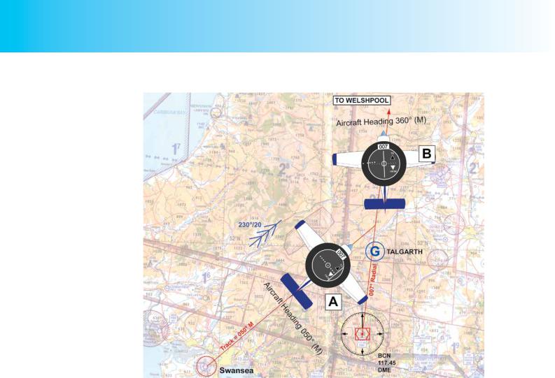
Figure 17.16 The Brecon VOR/DME and its location on the ‘half-mil’ chart. (Photo by kind permission of Trevor Diamond –www.trevord.com).
readout while you are tracking along the radial that leads to Welshpool, so that will be another vital piece of information to help you with your visual navigation and ETAs. Welshpool is about 55 nautical miles (nm) from the Brecon VOR/DME, but you have read from the En-Route (ENR) Section of the UK AIP that the Brecon VOR has a range of 65 nm, so that should be OK. In any case, at about 10 nm from Welshpool, you should be able to get a reliable signal from the Welshpool NDB to help you locate the airfield. You have checked the range of the Welshpool NDB in the Aerodrome
(AD) Section of the AIP, and seen that it is 10 nm. You note, too, that Welshpool has a DME with a range of about 15 nm.
Because you will be flying over mountainous terrain you elect to fly at Flight Level 50.
At that level, you should not suffer from terrain errors with either radio-navigation aid, although you have noted the warnings in the AIP concerning range and reception at Welshpool being affected by the surrounding high terrain. If the ambient pressure is within the normal range, Flight Level 50 will also put you well over 1 000 feet above the highest obstacle known to be en-route.
We will assume that the wind at Flight Level 50 is 230º/20 knots.
During your flight planning, you measure from the 1:500 000 Chart that the radial you require to intercept from Brecon VOR/DME, and along which you may track directly to Welshpool, is the 007° (M) radial. You note that as you will be tracking 007°(M), your chosen Flight Level of 050 is also in accordance with the Quadrantal
Rule. Although your flight is a VFR navigation flight, and you are not legally required to fly the Quadrantal Rule, doing so is recommended by the UK CAA and is good airmanship.
317
Order: 6026
Customer: Oleg Ostapenko E-mail: ostapenko2002@yahoo.com
Customer: Oleg Ostapenko E-mail: ostapenko2002@yahoo.com
CHAPTER 17: VHF OMNI-DIRECTIONAL RANGE (VOR)
Figure 17.17 Intercepting and maintaining a track of 007°(M) from the Brecon VOR/DME with a wind of 230°/20 knots.
Check for yourself all the basic flight planning considerations mentioned above by referring to your own copy of the 1:500 000 Chart of Southern England and Wales.
During the flight itself, provided everything works out as planned and provided you have set up your OBI correctly, you should expect the OBI to begin to respond about 4 or 5 nm beyond the town of Brecon as you track 050° (M) from Swansea. You wish to track along the 007° radial from the Brecon VOR, so, after having tuned your VOR receiver to Brecon (currently on 117.45MHz), and confirmed the expected morse identification code (BCN), you will have selected 007° against the radial indicator of the OBI. Because, when you are overhead the town of Brecon on a track of 050°(M), intercepting a 007°(M) track relative to the VOR beacon would lead you away from the beacon, the FROM flag will be showing, and the OBI is correctly set up for what you are planning to do, with the CDI acting as a demand indicator. As you close on the 007° radial from the Brecon VOR, you will be within 10° of that radial (i.e. 10° to the left of the radial) as you pass the 1093 feet spot height on your starboard side. The CDI will show, therefore, that you need to continue converging with the 007° radial from left to right. The CDI, being a demand indicator, in this OBI configuration, will, thus, be over to the right of the horizontal deviation scale “demanding” that you fly right. (See Figure 17.17 Position A.)
As you are on a track of 050°(M), you are already converging with the 007° radial from left to right, so you continue on track. From Position A in Figure 17.17 you will quickly close with the radial, especially given that you have a tail wind of 20 knots. The CDI will, therefore, quickly move towards the central position on the OBI. As the CDI reaches the right hand side of the inner circle showing that you are 2° to the left
318

ID: 3658
Customer: Oleg Ostapenko E-mail: ostapenko2002@yahoo.com
Customer: Oleg Ostapenko E-mail: ostapenko2002@yahoo.com
CHAPTER 17: VHF OMNI-DIRECTIONAL RANGE (VOR)
of the 007° radial, you begin a gentle turn to the left onto a suitable heading which will enable you to track 007° (M) away from the VOR beacon towards Welshpool. As the wind is from 230° (T) at 20 knots, you know that you will need to adopt an appropriate wind correction angle to maintain the track of 007°(M) once you are established on it. With no wind, you could simply head 007°(M), but life is rarely that simple. Therefore, you make any fine adjustments required to establish yourself on the 007° radial and then lay off the drift by a suitable amount.
You learned earlier in this chapter how to establish yourself on a VOR radial, and in Chapter 9 you learned how to correct for drift. So, if your true airspeed were to be 120 knots, you would have already calculated that the maximum drift you would experience in a 20 knot wind would be 10°. With a wind from 230° (T) (say, 233°(M)), then, your track of 007° (M) will mean that the wind is meeting your track at about 45° from behind. This means that you will be experiencing ¾ of the maximum drift; that is, a drift angle of about 7° or 8°. The drift will be to starboard, so you quickly work out that turning left by, say, 7° onto a heading of 360° (M), or, otherwise expressed, 000°(M), should enable you to stay on the 007° radial from Brecon VOR. You also work out, using the mental dead reckoning (MDR) techniques that you have mastered, that, with the wind from behind you at 45°, you will have a tailwind component of 15 knots ( ¾ x 20 knots ), giving you a groundspeed of 135 knots. You will be able to check your MDR calculations from the read-out of groundspeed on your DME display.
Your flying instructor will teach you the airborne techniques of intercepting and maintaining a track along a selected VOR radial.
Fixing Position using Radio-Navigation Aids.
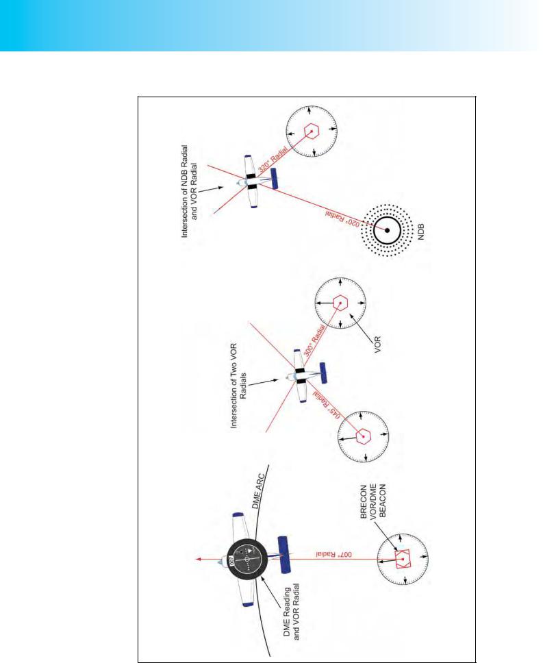
Using the knowledge you have learnt in this and preceding chapters, you should readily appreciate that you may fix your position over the ground, by using two selected radio-navigation aids and an aeronautical chart.
Provided you have the necessary airborne equipment, you may fix your position using a VOR/DME, two VORs, a VOR and an NDB, or two NDBs, in order of preference,, as depicted in Figure 17.18. Note that the ideal cross-cut between position lines is a right angle, which a VOR/DME fix will automatically provide. For a two-beacon fix, if tracking along a radial, choose a second beacon as nearly as possible abeam the aircraft.
319
Order: 6026
Customer: Oleg Ostapenko E-mail: ostapenko2002@yahoo.com
Customer: Oleg Ostapenko E-mail: ostapenko2002@yahoo.com
CHAPTER 17: VHF OMNI-DIRECTIONAL RANGE (VOR)
Figure 17.18 Fixing position using different combinations of radio-navigation aids.
320
ID: 3658
Customer: Oleg Ostapenko E-mail: ostapenko2002@yahoo.com
Customer: Oleg Ostapenko E-mail: ostapenko2002@yahoo.com
CHAPTER 17: VHF OMNI-DIRECTIONAL RANGE (VOR)
Establishing a Position Line When Passing Abeam a VOR Beacon.
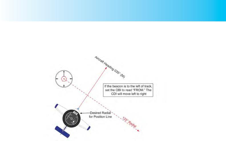
During a visual navigation flight, noting the time at which you pass at 90° abeam a VOR beacon, or any radial required for a specific fix, is a useful procedure for monitoring the progress of the flight. (See Figure 17.19)
Figure 17.19 Setting up an OBI so that the pilot knows when he is passing 90° abeam a
VOR beacon. If the beacon is to the left of track, select the radial FROM the beacon. The
CDI will then move from left to right as you pass abeam the beacon.
When using a VOR in this way, it is convenient to set up the OBI so that the CDI always moves in the same direction, say from left to right, as the aircraft passes abeam the VOR beacon, so that you are always aware when the aircraft has passed abeam and not left wondering whether the CDI has yet moved or not, because you cannot remember which side of the OBI it was on to start with. This simple procedure - of the CDI always moving from left to right - is easy to set up.
If the VOR beacon is to the left on your track, select on the OBI, using the OBS, the radial from the VOR beacon at which you wish to take your fix (usually the radial running at 90° to your track). The FROM flag will then be displayed and the CDI will be over to the extreme left of the OBI until you arrive within 10° of the selected radial. This situation is depicted in Figure 17.19. The CDI will, then, begin to move from left to right. As it passes through the centre of the OBI you are exactly abeam the VOR beacon or crossing your chosen radial, and the time at which you reach that position line is a good check on the progress of your flight.
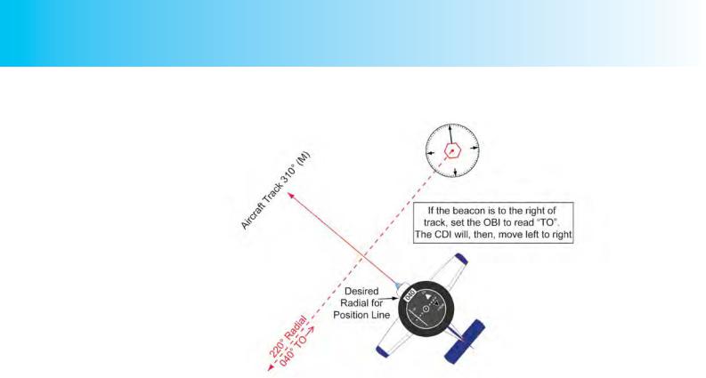
If the VOR beacon is to the right on your track, using the OBS, you select on your OBI the reciprocal of the radial at which you wish to take your fix (and, again, this will probably be the radial running at 90° to your track). Confirm that the TO flag is displayed. By doing this, the CDI will again be over to the extreme left of the OBI until you arrive within 10° of the selected radial. This situation is depicted in Figure 17.20, overleaf. The CDI will then begin to move from left to right. As before, when the CDI passes through the centre of the OBI you are crossing the radial.
This technique is known as the’ Port Published Rule’ - if the beacon is to Port, use the Published radial, if it is to the Right, use the Reciprocal.
321
Order: 6026
Customer: Oleg Ostapenko E-mail: ostapenko2002@yahoo.com
Customer: Oleg Ostapenko E-mail: ostapenko2002@yahoo.com
CHAPTER 17: VHF OMNI-DIRECTIONAL RANGE (VOR)
Figure 17.20 Setting up an OBI so that the pilot knows when he is passing 90° abeam, a VOR beacon. If the beacon is to the right of track select the radial TO the beacon. The CDI will then move from left to right as you pass abeam the beacon.
TYPES OF VOR.
There are various types of VOR. A brief description of each type is given below.
Broadcast VOR (BVOR).
A Broadcast VOR gives weather and airfield information (ATIS).
Doppler VOR.
A Doppler VOR has improved bearing accuracy.
Terminal VOR.
A Terminal VOR has low power and is used at major airfields, usually as a locator in conjunction with an Instrument Landing System (ILS) or for a VOR approach procedure.
VORTAC.
Co-located VOR and TACAN beacons. TACAN stands for Tactical Air Navigation and is military equipment fulfilling, in the civil and general aviation world, a similar function to VOR/DME.
FACTORS AFFECTING THE OPERATIONAL RANGE OF VOR
BEACONS.
Transmitter Power.
The higher the transmitter power of the VOR beacon, the greater the range of the VOR signals. Thus, en-route VORs with a 200 Watt transmitter will have a maximum range of about 200 nm, while a terminal VOR will normally transmit at 50 Watts to give a maximum range of about 100 nms.
322

ID: 3658
Customer: Oleg Ostapenko E-mail: ostapenko2002@yahoo.com
Customer: Oleg Ostapenko E-mail: ostapenko2002@yahoo.com
CHAPTER 17: VHF OMNI-DIRECTIONAL RANGE (VOR)
Transmitter Elevation and Receiver Height.
The transmitter elevation and receiver altitude will also have an effect on the operational range of VOR beacon. The transmissions, being VHF transmissions are line of sight. The range of VHF signals can be assessed by using the following formula:
Signal Range = 1.25 ( h1 + h2 ) nautical miles.
where h1 is receiver altitude in feet and h2 = transmitter elevation in feet
Uneven terrain, intervening high ground, mountains, man-made structures, and so on, cause VOR bearings to be stopped (screening), reflected, or bent (scalloping), all of which give rise to bearing errors. Where such bearing errors are known to exist, Air Information Publications will publish details.
APPROACHING AND FLYING OVERHEAD A VOR BEACON.
In the proximity of the VOR beacon, the radials are very close together, so as an aircraft approaches the beacon, a CDI, which is indicating that the aircraft is on a selected radial, becomes very sensitive, and will indicate large angular deviations from the selected radial, whenever an aircraft strays from track. Near the beacon, then, it is very important for a pilot to hold a steady heading. As the VOR-overhead is approached, the CDI may oscillate rapidly, and the ‘OFF’ flag may appear momentarily.
Figure 17.21 The Cone of Silence or Cone of Ambiguity.
The CDI will behave in this manner in the VOR overhead, because no signals are being sensed by the aircraft’s VOR receiver directly overhead the beacon. For this reason, the cone overhead the beacon is known as the cone of silence, or cone of ambiguity.
323
Order: 6026
Customer: Oleg Ostapenko E-mail: ostapenko2002@yahoo.com
Customer: Oleg Ostapenko E-mail: ostapenko2002@yahoo.com
CHAPTER 17: VHF OMNI-DIRECTIONAL RANGE (VOR)
DESIGNATED OPERATIONAL COVERAGE.
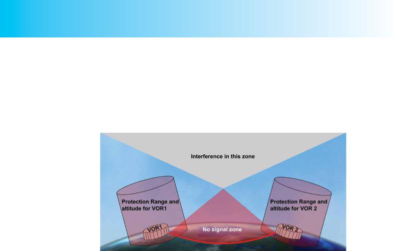
In order to guarantee that there is no interference between VOR beacons operating on the same frequency, known as co-frequencies, among the 160 frequencies available worldwide, it would be necessary to separate co-frequency beacons by at least twice their anticipated line-of-sight range. Transmitter power, propagation paths and the degree of co-frequency interference protection required necessitate that cofrequency beacons be separated for planning purposes by a greater distance.
Figure 17.22 Designated Operational Coverage of two VOR beacons.
In the United Kingdom, this protection is denoted by Designated Operational Coverage (DOC) figures, specified as a range and altitude. For example, a DOC of 50/25000 published in the UK AIP means that an aircraft should not experience co-frequency interference within 50 nms of a VOR beacon, up to a height of 25 000 feet. The DOC may also vary by sectors, (e.g. in the sector 315° to 345° from the beacon.).
Use of VOR beacon beyond its DOC can lead to navigation errors.
FACTORS AFFECTING VOR ACCURACY.
Site Error.
Site error is caused by uneven terrain such as hills and man-made structures, trees and even long grass, in the vicinity of the VOR transmitter. The error to radiated bearings is termed VOR course-displacement error. Ground VOR beacon site error is monitored to ± 1° accuracy.
Propagation Error.
Propagation error is caused by the fact that, having been broadcast with ±1° accuracy, the transmissions are further affected by terrain and distance. At considerable range from the VOR, bending or scalloping can occur.
Scalloping.
VOR scalloping is defined as an imperfection or deviation in the received VOR signal. Scalloping causes radials to deviate from their standard track and is the result of reflections from buildings or terrain. Scalloping can also cause the Course Deviation Indicator to flick from side to side.
324

ID: 3658
Customer: Oleg Ostapenko E-mail: ostapenko2002@yahoo.com
Customer: Oleg Ostapenko E-mail: ostapenko2002@yahoo.com
CHAPTER 17: VHF OMNI-DIRECTIONAL RANGE (VOR)
Airborne Equipment Errors.
Airborne equipment errors should be within a maximum of +/- 3°.
Aggregate Errors.
The above errors combine (or aggregate), to give a total error of +/- 5°. This will give a 5 nm across-track error at a range of 60 nm. (1 in 60 Rule)
Variation.
Variation is set at the ground station by the technicians, but if not updated frequently,as in the UK, can give rise to bearing errors. The rate of change of variation in the UK at
present is -7’/year, but in some parts of the world is significantly higher.
325

Order: 6026
Customer: Oleg Ostapenko E-mail: ostapenko2002@yahoo.com
Customer: Oleg Ostapenko E-mail: ostapenko2002@yahoo.com
CHAPTER 17: VHF OMNI-DIRECTIONAL RANGE (VOR) QUESTIONS
Representative PPL - type questions to test your theoretical knowledge of VHF Omni-Directional Range (VOR).
1.A VOR radial is most accurately defined as:
a.A magnetic bearing from the VOR station
b.A true bearing from the VOR station
c.A magnetic bearing to the VOR station
d.A true bearing to the VOR station
2.What is the approximate theoretical maximum range that a pilot would obtain from a VOR situated at 400 feet above mean sea level, in an aircraft flying at 2 500 feet?
a.3750 feet
b.100 nm
c.88 nm
d.70 nm
3.In which of the radio frequency bands does VOR operate?
a.Ultra High Frequency
b.Very High Frequency
c.Low Frequency
d.Micro Frequency
4.In what frequency range does VOR operate?
a.118 MHz to137 MHz
b.190 to 1750 kHz
c.1000 to 2000 MHz
d.108 MHz to 117.95 MHz
5.Which of the following phenomena does not affect VOR reception?
a.The terrain surrounding the VOR beacon
b.Transmitter elevation and receiver altitude
c.The cone of ambiguity overhead a VOR beacon
d.Coastal Refraction
6.For which of the following purposes may VOR be used?
a.To fly certain approach procedures
b.Identification of aircraft track by ATC controllers
c.Identification of individual aircraft by ATC controllers
d.The interpretation of heading guidance from radar controllers
326