

ppl_03_e2
.pdfID: 3658
Customer: Oleg Ostapenko E-mail: ostapenko2002@yahoo.com
Customer: Oleg Ostapenko E-mail: ostapenko2002@yahoo.com
CHAPTER 18: DISTANCE MEASURING EQUIPMENT (DME) QUESTIONS
Representative PPL - type questions to test your theoretical knowledge of Distance Measuring Equipment (DME).
1.The accuracy of DME equipment fitted to a modern aircraft is:
a.± 3% of range or 0.5 nm whichever is the greater
b.± 1.25% of range
c.± 3% of range
d.± 0.2 nm
2.What condition must prevail for DME equipment on an aircraft’s instrument panel to give a usable groundspeed reading?
a.The aircraft must have the DME ground station on its port beam
b.The aircraft must have the DME ground station on its starboard beam
c.The aircraft must be heading directly towards the ground station
d.The aircraft must be heading directly towards or away from the ground station
3.In a time interval of one minute, your DME instrument shows that your aircraft has travelled 1.7 nautical miles directly towards a VOR/DME beacon, what is the groundspeed of the aircraft?
a.102 knots
b.110 knots
c.96 knots
d.100 knots
4.On which of the following principles does Distance Measuring Equipment function?
a.The principle of VHF direction finding
b.The principle of primary radar
c.The principle of secondary radar
d.The principle of VHF omni-directional ranging
5.The DME instrument in the aircraft gives the ……………. distance read out from the beacon.
a.Horizontal
b.Slant
c.Oblique
d.Return
337

Order: 6026
Customer: Oleg Ostapenko E-mail: ostapenko2002@yahoo.com
Customer: Oleg Ostapenko E-mail: ostapenko2002@yahoo.com
CHAPTER 18: DISTANCE MEASURING EQUIPMENT (DME) QUESTIONS
6.What is the nature of a DME “position line”?
a.It is the circumference of a circle, centred on the ground beacon whose radius is the distance of the aircraft from the beacon
b.It is a radial emanating from the ground beacon whose length is the distance of the aircraft from the beacon
c.It is a straight position line measured in degrees magnetic
d.It is a straight line from the ground beacon, which is identified by a Course Deviation Indicator and whose length is the distance of the aircraft from the beacon
7.Give an approximate value for the theoretical maximum range of a DME beacon in respect of an aircraft flying at 3000 feet?
a.55 nautical miles
b.60 nautical miles
c.70 nautical miles
d.3000 nautical miles
Question |
1 |
2 |
3 |
4 |
5 |
6 |
7 |
Answer |
|
|
|
|
|
|
|
The answers to these questions can be found at the end of this book.
338
Customer: Oleg Ostapenko E-mail: ostapenko2002@yahoo.com
CHAPTER 19
RADAR
339

Order: 6026
Customer: Oleg Ostapenko E-mail: ostapenko2002@yahoo.com
Customer: Oleg Ostapenko E-mail: ostapenko2002@yahoo.com
CHAPTER 19: RADAR
340
ID: 3658
Customer: Oleg Ostapenko E-mail: ostapenko2002@yahoo.com Customer: Oleg Ostapenko E-mail: ostapenko2002@yahoo.com
CHAPTER 19: RADAR
INTRODUCTION.
When radar was first developed in Britain, and used to great effect in the defence of the country in World War 2, it was called Radio Direction Finding (RDF). The word “radar” is an American acronym, coined in 1941, which stands for Radio Detection and Ranging. It is the American word which survived - better describing the capability of the system - and became current worldwide.
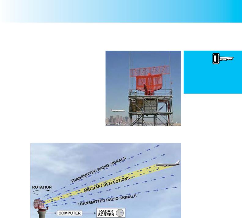
Radar is based on the principle of transmitting radio waves from a special type of rotating antenna, or radar head (see Figure 19.1), and then detecting the return-signals after they have been reflected from a remote object, as depicted in Figure 19.2.
Figure 19.1 A terminal area surveillance radar at an airport. The radar head makes approximately 10 rotations per minute.
Radar is
based on the principle of
transmitting
radio waves from a ground station and then detecting the return-signals which have been reflected from a “target” aircraft.
Figure 19.2 Radar is based on the principle of transmitting radio waves, and then detecting the direction and range of the target-object from the reflected signals.
THE PRINCIPLE OF OPERATION OF RADAR.
Radar is able to detect the direction and range of objects at distances from the ground station over which the object is invisible to the human eye, even when aided by powerful telescopes. As the reflected radar signals are received at the ground station, the precise direction of the target object is detected, while the time lapse, from transmit to receive, of the radio signals is also measured to give the range of the target. You have learned about the relationship between speed, distance and time in Chapter 4, and may remember the formula:
distance = speed × time
341
Order: 6026
Customer: Oleg Ostapenko E-mail: ostapenko2002@yahoo.com
Customer: Oleg Ostapenko E-mail: ostapenko2002@yahoo.com
CHAPTER 19: RADAR
One of the primary aims
of a radar controller
is to keep aircraft safely separated from one another.
When radar is not available,
separation is achieved
procedurally, based on position and altitude reports from pilots.
Radio waves are electromagnetic waves which travel at the speed of light, so given that light travels at 299 792 458 metres per second, or 161 888 nautical miles (nm) per second, you can see that a computer can instantly calculate the range of an aircraft from the simple expression:
range in nm = 161 888 nm/sec × |
signal out and return time |
secs |
|
2 |
|
||
|
|
|
|
PRESENTATION OF RADAR INFORMATION.
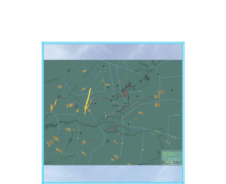
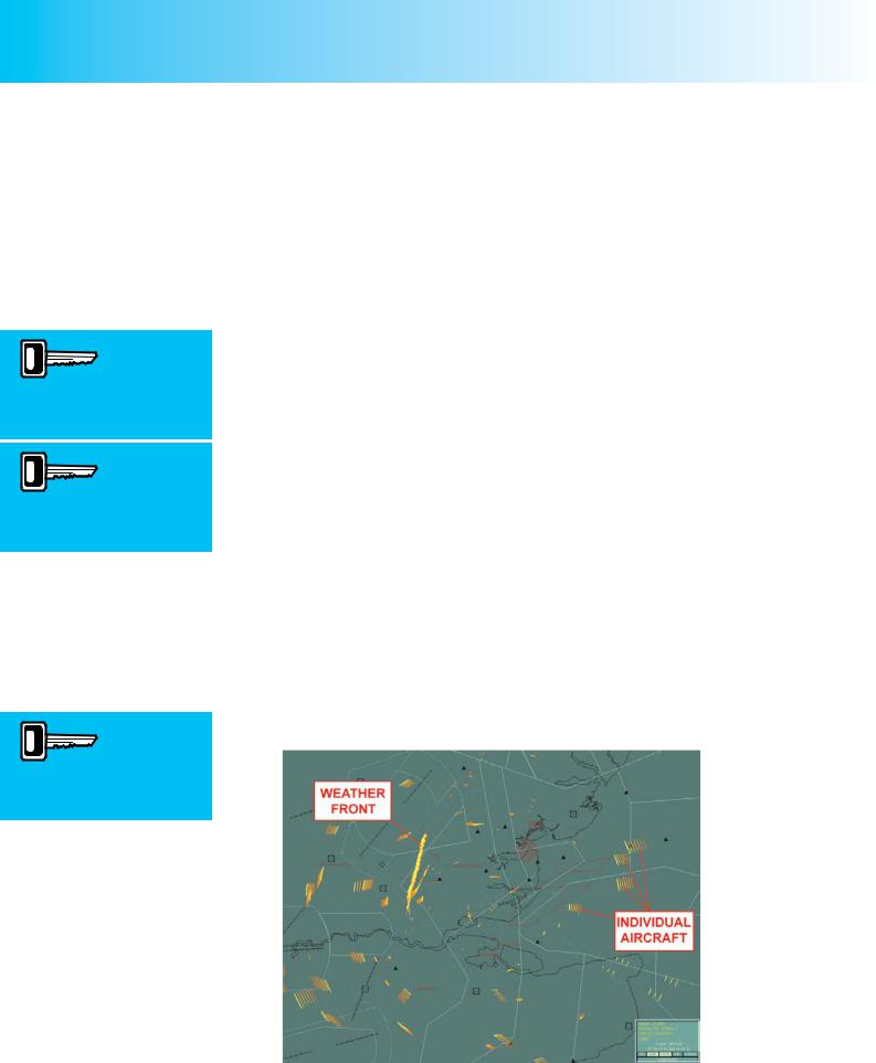
The reflected signal from a “target” aircraft appears as a “trace” on the radar screen, enabling an air traffic controller to “see” the aircraft. (See Figure 19.3.)
Maps and coastlines within a particular airspace can also be represented on the radar screen so that an air traffic controller can relate the blips on his screen to an aircraft’s position over land or sea. The controller can also see the position of aircraft in relation to one another and the direction in which they are flying; this information is used to ensure that the aircraft under his control are kept safely separated from one another.
In the days before radar (or where radar is not available) separation was achieved procedurally, based on position and altitude reports from pilots. This type of separation is called procedural separation.
The reflected signals from
a “target” aircraft
appear as a trace on the controller’s radar screen.
THE RADAR SCREEN.
The rotating radar head transmits a radio beam which will detect a “target” aircraft when the beam is directed at it. The return from the aircraft is “painted” on the air traffic controller’s radar screen as a trace. As the aircraft advances in its flight, the trace also moves across the radar screen, leaving a tail of light behind it, as depicted in Figure 19.3. On computer processed radar screens, the trace is shown with a trail of dots.
From the direction of movement and the trail of the trace, the air traffic controller can see the direction and speed of flight of the target aircraft.
Figure 19.3 Primary Radar returns in the East London area, shown on a radar display of London Southend Airport.
(Photo by kind permission of London Southend Airport Co Ltd.)
342
ID: 3658
Customer: Oleg Ostapenko E-mail: ostapenko2002@yahoo.com Customer: Oleg Ostapenko E-mail: ostapenko2002@yahoo.com
CHAPTER 19: RADAR
APPLICATIONS OF GROUND-BASED RADAR SYSTEMS.
Ensuring separation between aircraft is a prime responsibility of radar controllers. Other applications of ground-based radar systems are listed below.
•Aircraft under radar control can be instructed to steer given headings, climb, descend, and maintain altitude.
•Aircraft may be “slotted” into to a landing sequence, with adequate spacing, in order to ensure the safety of all on board. In this way, radar systems enable aircraft movements to take place at the speeds required by today’s high-volume air traffic environment without any detriment to safety.
•Radar enables a controller to provide pilots of aircraft who may, or may not, be under his direct control with headings to steer (known as radar vectoring) in order to avoid conflict with other aircraft. In the United Kingdom, general aviation pilots may request this type of radar advisory service using the Lower Airspace Radar Service (LARS) provided by certain aerodromes.
The issuing of
instructions to pilots by radar
controllers in
order that aircraft may avoid conflicting with other traffic, or be led into an instrument or procedural landing system, is known as “radar vectoring”.
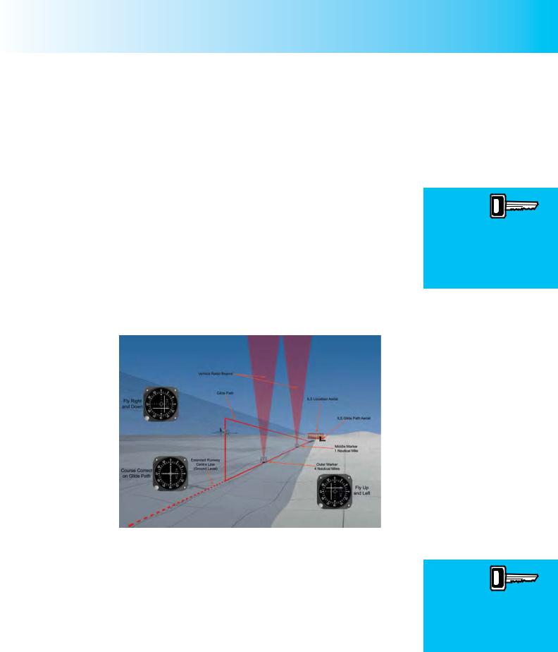
•Radar vectors are also given by controllers to pilots in order to lead aircraft into an Instrument Landing System approach.
Figure 19.4 Controllers can pass radar vectors to pilots to lead them into an Instrument Landing System procedure.
•The radar controller can provide basic information to pilots about the position and heading of other potentially conflicting traffic. This type of radar information service is a further service provided in the United Kingdom by LARS.
•Ground radar, or Airfield Surface Movement Radar is used to assure the safety of aircraft and vehicles on runways, taxiways and aprons, particularly in poor visibility.
The previous examples of radar applications fall under the heading of surveillance or primary radar. Primary surveillance radar requires no particular equipment to be carried aboard the aircraft for a pilot to be able to benefit from the radar service.
General
aviation pilots flying in
uncontrolled
airspace may benefit from a radar service by requesting a Lower Airspace Radar Service from participating ATCUs.
343
Order: 6026
Customer: Oleg Ostapenko E-mail: ostapenko2002@yahoo.com
Customer: Oleg Ostapenko E-mail: ostapenko2002@yahoo.com
CHAPTER 19: RADAR
The term secondary surveillance radar is used to describe the use of ground radar systems which operate in conjunction with aircraft fitted with specialised equipment known as “transponders”. Secondary surveillance radar is covered in Chapter 20.
USE OF RADAR.
Air Traffic Control Services use radar extensively to serve a large number of requirements and users. The most common radar systems used by ATC are described briefly below.
En-Route Surveillance Radar (RSR).
En-route surveillance radars are long-range radars, typically of 200 to 300 nm range, which are used for airways surveillance to provide air traffic control with the range and bearing of all aircraft flying in airways, within their area of responsibility.
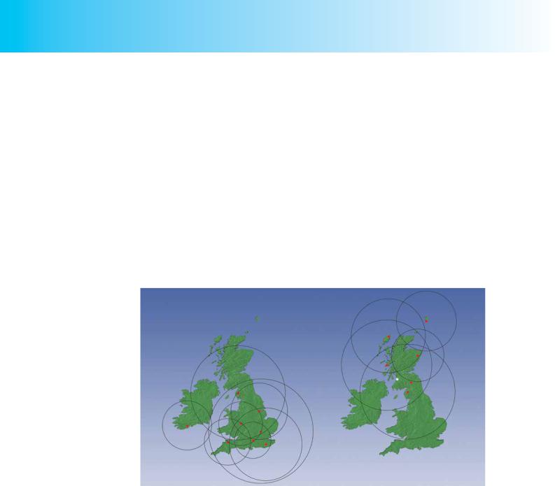
Figure 19.5 shows the locations and coverage of the London Area Control
Centre and the Scottish Area Control Centre radars.
Figure 19.5 En-route surveillance radar.
Terminal Area Surveillance Radar.
Terminal area surveillance radars have a range of up to 75 nm, and are used for controlling traffic in Terminal Areas.
Aerodrome Surveillance Approach Radars.
Aerodrome surveillance approach radars are short-range radars, providing positional information up to 25 nm range. They provide:
•Positional information and control of aircraft approaching an aerodrome.
•Radar vectoring to the final approach of an Instrument Landing System (ILS).
•Surveillance radar approaches.
344
ID: 3658
Customer: Oleg Ostapenko E-mail: ostapenko2002@yahoo.com Customer: Oleg Ostapenko E-mail: ostapenko2002@yahoo.com
Figure 19.6 A Surveillance Radar Approach.
CHAPTER 19: RADAR
A surveillance radar approach is a non-precision airfield approach aid. Surveillance radar approaches usually require the aircraft to approach on a 3° glideslope. To maintain a 3° glideslope, the aircraft must lose approximately 300 feet of height for every one nautical mile travelled horizontally. Therefore, if the aircraft’s groundspeed is 120 knots (2 nm per minute), it must descend at 600 feet per minute, and, at a groundspeed of 90 knots (1½ nautical miles per minute), an aircraft must descend at 450 feet per minute. Therefore, if carrying out a surveillance radar approach, in order to remain on the glideslope of 3°, the pilot may calculate rate of descent using the following approximate rule:
Halve groundspeed in knots and add “0” to the result to obtain the rate of descent, in feet per minute, which will result in a glideslope of 3°.
Precision Approach Radar (PAR).
Precision Approach Radar is a runway approach aid. precision approach aid which can be aligned with any runway at its base airfield. PAR is only available at certain military airfields.
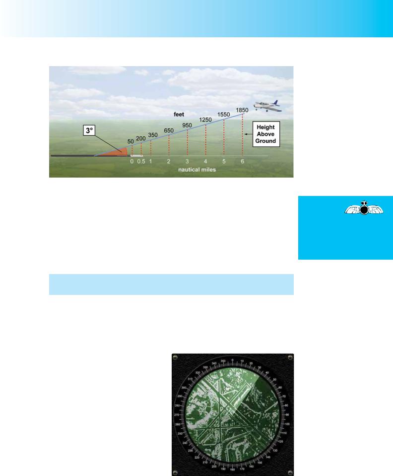
Airport Surveillance Detection Equipment.
Airport Surveillance Detection Equipment, also known as Airfield Surface Movement Radar, is installed at major airfields. It provides a very accurate radar display, in all weathers and visibilities, of the aerodrome infrastructure: taxiways, runways, aprons etc. (See Figure 19.7.) In particular, it shows vehicular traffic and aircraft that are stationary, taxiing, landing or taking off.
This type of radar is designed to provide a detailed, bright and flicker-free display of all aircraft and vehicles on runways
and taxiways so that Air Traffic Control
Officers can be certain that runways Figure 19.7 Airfield Surface Movement Radar.
To descend
at an angle of approximately
3°, take your groundspeed in knots (e.g. 90 knots), halve it (45 knots) and add 0 to obtain the required rate of descent of 450 feet per minute.
345

Order: 6026
Customer: Oleg Ostapenko E-mail: ostapenko2002@yahoo.com
Customer: Oleg Ostapenko E-mail: ostapenko2002@yahoo.com
CHAPTER 19: RADAR
are clear of traffic before landings or take-offs. Using this surface movement radar, controllers can also ensure the safe and orderly movement of traffic on taxiways; it is especially valuable in very poor visibility.
RADAR FREQUENCIES.
Radarfrequencies areVHFand higher,thefrequencyband forairtrafficcontrolradars being in the 1-4 Gigahertz (GHz) range. The short wavelengths at these frequencies mean that signals are transmitted in narrow beams which are required for effective target discrimination and bearing measurement. Furthermore, the reflection of radar transmissions from aircraft is more effective, in terms of clear target discrimination, the greater the difference between the wavelength of the signal and the size of the object being targeted.
In general, the higher the frequency of the radar transmissions, the smaller the object that can be detected by the radar beam.
RANGE.
The range of primary surveillance radar is affected by the following factors.
•Transmitter power. Aradar signal attenuates with increasing distance from the transmitter, and, of course, a radar signal has to travel from the transmitter to the target aircraft and back again to the transmitter. The theoretical range of a radar transmitter is proportional to the fourth root of the transmitter power. The higher the transmitter power, the greater the range.
•The properties of the target object. Metal is more effective than wood at reflecting radar signals. The size and shape of the target also affect the effective range of radar. The design of military stealth aircraft exploits all of these parameters.
•Elevation of the radar head and altitude of the aircraft. Radar transmissions, because of their frequency band, travel in straight lines, and, thus, their range is subject to the line-of-sight limitation. Aircraft may be undetectable by radar because of the curvature of the Earth and because they are flying low, and are screened by intervening high ground. The theoretical maximum range of a radar transmitter is, thus, arrived at by using the same formula as that which gives the range of a VOR beacon:
Maximum range in nautical miles = 1.25 × (stth1 + stth2)
where h1 = elevation of radar head in feet h2 = altitude of aircraft in feet
•Atmospheric conditions. Certain atmospheric conditions, such as temperature inversions and increasing humidity with altitude, can increase the range of radar by causing beam refraction. Other atmospheric conditions, for instance, very heavy rain, can reduce the range of radars.
346