Добавил:
Опубликованный материал нарушает ваши авторские права? Сообщите нам.
Вуз: Предмет: Файл:

ppl_03_e2

.pdf
Скачиваний:
3436
Добавлен:
26.01.2018
Размер:
23.49 Mб
Скачать

ID: 3658

Customer: Oleg Ostapenko E-mail: ostapenko2002@yahoo.com

Customer: Oleg Ostapenko E-mail: ostapenko2002@yahoo.com

CHAPTER 17: VHF OMNI-DIRECTIONAL RANGE (VOR)

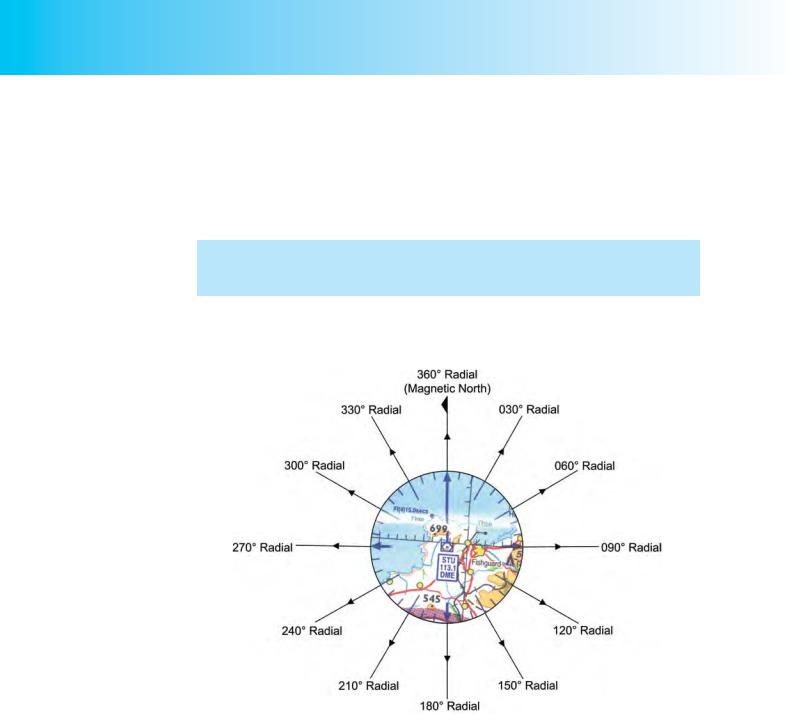
Figure 17.4 shows the VOR beacon (co-located with a Distance Measuring Equipment (DME) Facility) located at Strumble near Fishguard, indicated by a compass rose aligned with respect to Magnetic North. A photograph of the actual beacon is also shown.

Notice how the four arrows of the VOR compass rose point away from the beacon symbol. This fact should help you remember that VOR radials are always identified by their bearing away (radiating) from the VOR beacon.

Range and Accuracy.

The range of a VOR transmission depends on the power of the beacon and on the VHF line-of sight limitation. For a transmitter of a given power rating, the higher an aircraft’s altitude, the greater will be the range at which it can receive and use VOR transmissions. When aircraft, such as airliners, operate at very high altitude they are liable to suffer interference from VORs which, though widely separated from one another, are transmitting on the same frequency.

Information on the lateral and vertical range (Designated Operational Coverage (DOC)) of VORs is contained in the En-Route (ENR) section of the United Kingdom Aeronautical Information publication (UK AIP) (ENR 4-1-1). For instance, the AIP tells us that the Strumble VOR/DME has a DOC which varies from 85 nautical miles (nm) to 300 nm, depending on the bearing sector of the transmission, and that it can be used up to an altitude varying from 50 000 feet to 70 000 feet (again depending on the bearing sector), without the likelihood of interference from other VOR beacons. Coastal VOR beacons tend to be more powerful and have a longer range than inland VOR beacons. Cranfield VOR, an inland beacon, has a published DOC of

50 nm/25 000 feet.

VOR systems are very accurate, capable of achieving an accuracy of under of error. However, airborne equipment error can be up to about +/- 3°. The aggregate of all errors to which the VOR is susceptible is around +/- 5°.

Uses of VOR.

The VOR has become one of the world’s primary short range radio-navigational aids because of its accuracy, reliability and ease of pilot-interpretation. Though the range of VOR is restricted by the VHF line-of-sight limitation, the system suffers from few of the disadvantages to which the NDB/ADF system is prone. VOR is not so liable to be affected by the proximity of electrical storms, and, because its signals are line-of-sight, the VOR does not suffer from night effect caused by the reflection of lower frequency signals from the ionosphere. Neither are VOR signals susceptible to bending around terrain features or when crossing coastlines.

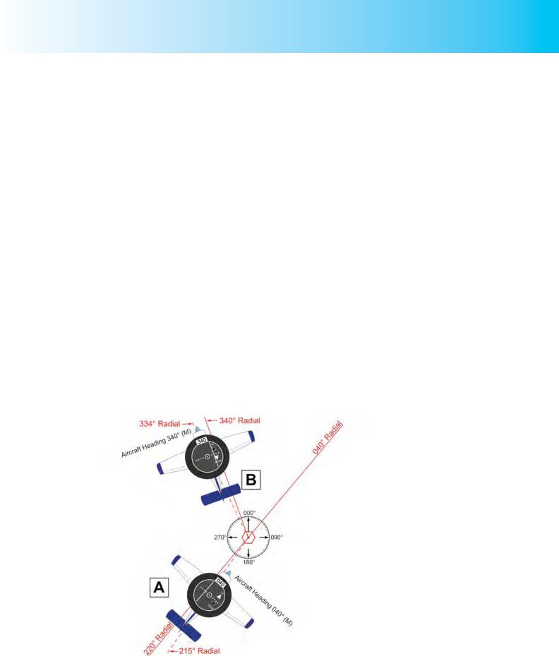
Using the VOR system, a pilot may navigate from one VOR beacon to another, or, if he has two VOR receivers and displays in his aircraft, track towards or away from one VOR beacon, along any chosen radial, and then intercept a designated radial from a second VOR beacon, and turn to track towards that beacon.

A pilot may determine his position by selecting two different VOR beacons, noting his magnetic bearing from each beacon, and drawing the lines on his chart. The compass rose, aligned on Magnetic North, which surrounds the VOR beacon locations on the

1:500 000 Chart, helps the pilot to fix his position in the air.

Ground fixes may also be determined approximately by drawing a VOR radial which cuts a large angle across a significant and unique line feature on the ground, such as a particular stretch of coastline. And, as you will learn in a later chapter, position may be determined by reading off a DME range along a selected VOR radial.

VOR radials

are always identified by

their bearing

away from the VOR beacon

307

Order: 6026

Customer: Oleg Ostapenko E-mail: ostapenko2002@yahoo.com

Customer: Oleg Ostapenko E-mail: ostapenko2002@yahoo.com

CHAPTER 17: VHF OMNI-DIRECTIONAL RANGE (VOR)

Most airways systems were developed with VORs determining the routes, giving aircrew much better instrument presentation than the older NDBs and Marker beacons. Navigational reference points, or waypoints, can also be defined by the point at which two radials from different VOR beacons intersect each other, or by a VOR radial and a DME distance intersection.

Other uses of VOR are:

As a let-down and approach aid at aerodromes, using published procedures.

As a holding beacon.

VOR AIRBORNE EQUIPMENT.

Aerials.

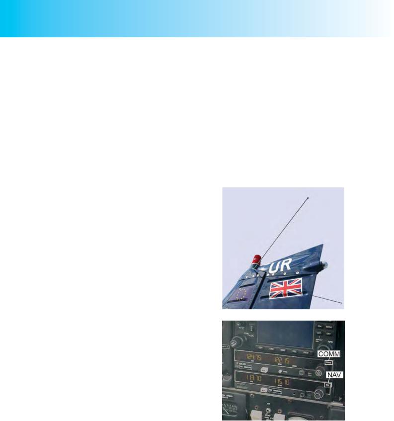
On low-speed, light aircraft, the VOR aerial is normally a whip-type aerial fitted on the fin or beneath the forward part of the fuselage. (See Figure 17.5.)

On high-speed aircraft, VOR antennae are usually blade-type aerials, or else are mounted flush with the airframe;

again, often on the fin.

The VOR Receiver.

The frequency operating range of the VOR beacon is from 108.00 MHz to 117.95 MHz, a range which is just below the VHF voice communication range of 118 MHz to just under 137 MHz.

The airborne element of VOR requires a dedicated receiver, often labelled NAV, and which in many aircraft is located alongside the COMM receiver. (See Figure 17.6.)

VOR Instrument Displays.

Omni Bearing Indicators.

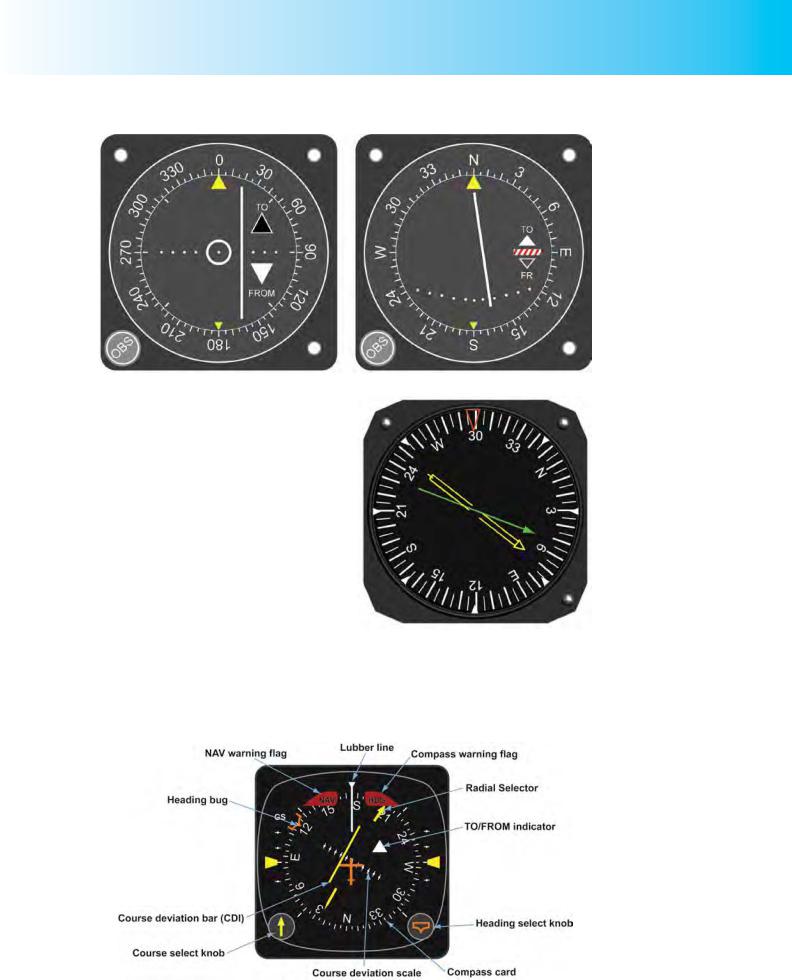
You may see several types of VOR instrument display, but the most widely used in light aircraft are the types illustrated at Figures 17.7 which are sometimes called Omni Bearing Indicators (OBI) for reasons which should become clear as you work your way through this chapter.

Figure 17.5 A whip-type VOR aerial.

Figure 17.6 The VOR receiver (NAV) alongside the VHF voice communication receiver (COMM).

308

ID: 3658

Customer: Oleg Ostapenko E-mail: ostapenko2002@yahoo.com

Customer: Oleg Ostapenko E-mail: ostapenko2002@yahoo.com

CHAPTER 17: VHF OMNI-DIRECTIONAL RANGE (VOR)

Figure 17.7 Two types of Omni Bearing Indicator.

Radio Magnetic Indicators.

A VOR indicator may also be incorporated in a Radio Magnetic Indicator (RMI) (see Chapter 16), as depicted in Figure 17.8. RMIs of this type usually have two pointers often of a different colour, one which receives inputs from an ADF receiver, normally the broader of the two needles, and one, the narrower of the two, which receives inputs from the VOR receiver. The head of each needle indicates the QDM to the respective beacon. When an aircraft has two VOR receivers with one RMI, the needle will be switchable between the VORs.

Figure 17.8 An RMI with VOR and NDB indiacations.

Horizontal Situation Indicators.

The Horizontal Situation Indicator (HSI) (see Figure 17.9) combines a direction indicator, slaved to a master magnetic compass, with a VOR indicator. The HSI shows the aircraft’s magnetic heading and its orientation with respect to a selected

Figure 17.9 A Horizontal Situation Indicator.

309

Order: 6026

Customer: Oleg Ostapenko E-mail: ostapenko2002@yahoo.com

Customer: Oleg Ostapenko E-mail: ostapenko2002@yahoo.com

CHAPTER 17: VHF OMNI-DIRECTIONAL RANGE (VOR)

VOR radial, whether the aircraft is on the radial, paralleling the selected radial, on an interception heading to the radial, or diverging from it. HSIs are very easy to interpret and are fitted to almost all commercial aircraft. But, being expensive to acquire, they are not often found in light aircraft operated by flying clubs. For this reason, we will use the Omni Bearing Indicator (OBI) to illustrate the teaching points made in this chapter.

For the purposes of this chapter, we will use the OBI type of VOR indicator, as it is the most common VOR instrument display in basic single engine general aviation aircraft.

OBI Indications.

As you have already learnt, a VOR beacon transmits radials relative to Magnetic

North at the VOR beacon’s location. (See Figure 17.10.)

Figure 17.10 A VOR beacon transmits continuous radials through 360º.

A VOR display of the OBI type is able to indicate any radial selected by the pilot, using the Omni Bearing Selector (OBS) knob on the front of the instrument. Consequently, any radial emanating from the VOR beacon can be used by the pilot as position lines to help him fix the position of his aircraft, or as tracks that he can follow, either to or from the VOR beacon.

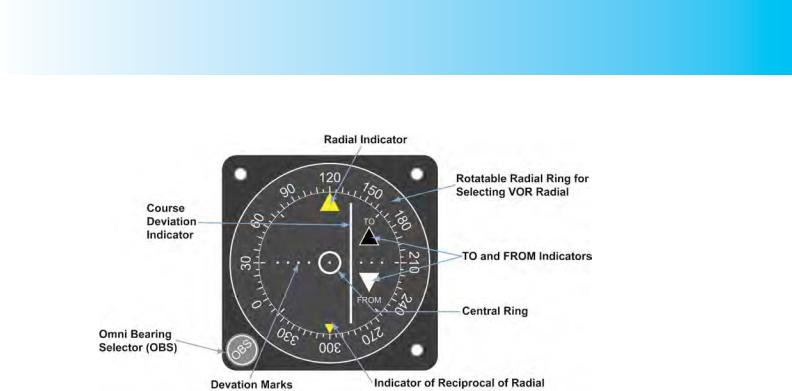
Let us examine, first of all, the component parts of the OBI VOR display, how the instrument functions, and the nature of its indications. The different elements of the OBI instrument and its display are illustrated at Figure 17.11, opposite.

The radial ring, calibrated from 0° to 360° at 5° intervals, is rotated by the pilot to select any VOR radial, either in order to obtain a position line or to select a track along which he wishes to fly TO or FROM the VOR beacon. In Figure 17.11, opposite, the

310

ID: 3658

Customer: Oleg Ostapenko E-mail: ostapenko2002@yahoo.com

Customer: Oleg Ostapenko E-mail: ostapenko2002@yahoo.com

CHAPTER 17: VHF OMNI-DIRECTIONAL RANGE (VOR)

Figure 17.11 The Omni Bearing Indicator.

120° radial has been selected against the radial indicator, in the 12 o’clock position. The pilot uses the Omni Bearing Selector, or OBS knob, to rotate the radial-ring and select a radial which he wishes to intercept and along which he wishes to fly to or from the VOR beacon, or to display a radial to be used for fixing.

When the Course Deviation Indicator (CDI) (the word “Course” here is synonymous with “track”) is on the middle dot within the white ring at the centre of the instrument, the aircraft is on the radial which has been selected in the 12 o’clock position by the OBS knob. Because the CDI can be placed in the centre position by turning the OBS knob, the pilot can determine, any time he wishes, what radial he is on, relative to the VOR beacon to which the VOR receiver is tuned.

Once a radial is selected under the radial indicator, the CDI, as its name implies, will indicate any deviation from the selected radial. The CDI will move left or right of the centre marker to indicate by how many degrees the aircraft is off the selected radial. Each marker, which has the form of a dot, represents a 2° deviation from the selected radial. The maximum deviation indicated is 10°. When showing a deviation from a desired radial, the CDI also acts as an indicator of which way the pilot must turn to regain the radial. (You will learn more about this function, below.) In Figure 17.11, the aircraft is 4° off the selected radial of 120°. (Note that the circumference of the white central ring represents the first 2° deviation from the selected radial.)

When a radial has been selected under the radial indicator, the TO-FROM indicator (in the form of a white arrowhead visible through one of the two triangular apertures) tells the pilot whether, by heading in the direction of the selected radial, he would be flying to or from the VOR beacon.

Flying TO or FROM the VOR Beacon.

Figure 17.12,overleaf, represents three radials emanating from a VOR beacon. You will see that for each of the three aircraft situated at a position on the three radials, the CDI of the OBI is in the middle. We will assume that the pilot of each aircraft, wishing to locate the position of his aircraft with respect to the VOR beacon, has tuned his VOR receiver to the VOR beacon’s frequency and rotated the OBS on the OBI until the CDI is positioned in the middle of the central ring, with the FROM indicator showing.

311

Order: 6026

Customer: Oleg Ostapenko E-mail: ostapenko2002@yahoo.com

Customer: Oleg Ostapenko E-mail: ostapenko2002@yahoo.com

CHAPTER 17: VHF OMNI-DIRECTIONAL RANGE (VOR)

Figure 17.12 With the aircraft in the positions shown relative to the VOR beacon, and the respective radials selected on the OBI, the CDI will be in the middle, and the OBI will indicate FROM, whatever the aircrafts’ heading.

This action on the part of the pilot has identified the radial by indicating its bearing from the VOR beacon against the radial indicator on the OBI. The three radials selected are 070°, 220° and 290°.

Note that the OBI does not register or display heading information. When the aircraft is situated on the radial selected against the radial indicator, the CDI will be in the middle of the OBI regardless of heading.

Of course, if the pilot wished his aircraft to remain on the selected radial, he would have to track along that radial. If there were no wind, that would mean that, in order to track away from the VOR beacon on the selected radial, he would have to fly the same heading as the bearing which appears against the radial indicator. If he wished to track to the VOR beacon along the selected radial, still assuming no wind, he would have to fly on the reciprocal heading.

The TO and FROM arrowheads make it easy for the pilot to orientate himself with respect to the VOR beacon.

Radials, as you have learnt, are, by convention, identified by their bearing in degrees magnetic from the VOR beacon. Consequently, in Figure 17.12, with the 070°, 220° and 290° radials selected on the OBI against the radial indicator, the FROM arrowhead indication is displayed.

It is important to note, however, that, for any given radial, the CDI can be centralised by selecting either of two numbers against the radial indicator: the number of degrees identifying the radial itself; that is, its bearing from the VOR station, and the number of degrees which identifies the reciprocal of the radial and, thus, indicates the bearing to the VOR station.

312

ID: 3658

Customer: Oleg Ostapenko E-mail: ostapenko2002@yahoo.com

Customer: Oleg Ostapenko E-mail: ostapenko2002@yahoo.com

CHAPTER 17: VHF OMNI-DIRECTIONAL RANGE (VOR)

The OBI does

not give any indication of

an aircraft’s

heading. It only indicates the position of the aircraft with respect to the selected radial.

Figure 17.13 With the aircraft in the positions shown relative to the VOR beacon, and the reciprocal of the respective radials selected on the OBI, the CDI will be in the middle, and the OBI will indicate TO, whatever the aircrafts’ heading.

Consequently, with the reciprocal of the radial selected, the CDI is again centred, indicating to the pilot that if he flies in that direction he will be flying to the VOR station. As you see in Figure 17.13, with the reciprocals 250°, 040° and 110° selected, the TO arrowhead appears on the OBI, irrespective of the heading of each aircraft.

The TO flag, then, is telling the pilot that, from his present position on the

220° radial, if he tracks in the direction of the reciprocal radial, which he has selected on the OBI, he will be flying to the VOR beacon. But the OBI takes no account at all of the present heading of the aircraft. The OBI simply tells the pilot where his aircraft is positioned, with respect to the selected radial, or its reciprocal (Figure 17.13 shows that he is on the reciprocal), and the TO or FROM indication tells the pilot whether he will fly to or from the beacon by steering the heading indicated by the selected radial.

Figure 17.14, overleaf, depicts an aircraft in two positions relative to a VOR beacon. In Position A, the aircraft is on the 220° radial with 040° selected on the OBI against the radial indicator. Whatever the aircraft’s heading (See Figure 17.14), the OBI would indicate TO, because, from its present position, a heading of 040° on the 220° radial will take the aircraft to the VOR beacon. The pilot also knows, from the central position of the CDI, that he is on the required radial and, that, with no wind blowing, by heading in the direction selected on the OBI, he is flying directly to the VOR beacon. In Position B, the pilot has overflown the VOR beacon, and is holding the heading 040°; the OBI now indicates FROM, telling the pilot that he is flying away from the VOR beacon. The OBI would have changed its indication from TO to FROM as the pilot flew over the VOR beacon. The CDI remains in the central position, so the pilot knows that he is tracking away from the VOR beacon on the 040° radial.

313

Order: 6026

Customer: Oleg Ostapenko E-mail: ostapenko2002@yahoo.com

Customer: Oleg Ostapenko E-mail: ostapenko2002@yahoo.com

CHAPTER 17: VHF OMNI-DIRECTIONAL RANGE (VOR)

Figure 17.14 In Position A, the aircraft is on the 220° radial with 040° set on the OBI. The CDI is in the middle and the OBI indicates TO because a heading of 040°(M) will take the aircraft to the VOR beacon. In Position B, the aircraft is now tracking away from the beacon along the 040° radial and the OBI indication has changed to FROM.

A Wind Correction Angle Must be Applied to Maintain Track Along a Selected Radial.

If there were a wind blowing (as there almost invariably will be), and if there were a crosswind component relative to a selected radial along which a pilot wished to track, the pilot would have to apply a wind correction angle in order to make good the track, in exactly the same manner as making good a track using visual navigation techniques.

TRACKING TO OR FROM A VOR BEACON.

Let us summarise briefly the main points that we have learned so far about using the

OBI type of VOR indicator. First of all, in order to use the information available from the VOR system, you must carry out the following initial actions.

Tune the VOR receiver to the desired VOR beacon by selecting the VOR beacon’s frequency on the receiver.

Check that your VOR equipment is functioning by checking that no Offflag is displayed on the OBI, if so equipped.

Confirm that the VOR beacon is the one you wish to use by listening to its morse identification.

Once you are happy that you are tuned to a desired VOR beacon, by rotating the Omni Bearing Selector (OBS) knob and positioning the Course Deviation Indicator

(CDI) in the centre of the instrument, and ensuring that the FROM flag is displayed,

314

ID: 3658

Customer: Oleg Ostapenko E-mail: ostapenko2002@yahoo.com

Customer: Oleg Ostapenko E-mail: ostapenko2002@yahoo.com

CHAPTER 17: VHF OMNI-DIRECTIONAL RANGE (VOR)

you can determine on which radial your aircraft is situated relative to the beacon. (See Figure 17.12.) A handy mnemonic is TIDY - Tune and Ident the beacon, set or check the Display is as required or expected, and then you can Yuse it (!).

Regaining Track.

If you centralise the CDI so that the TO flag is displayed, the OBI would display the reciprocal of the radial against the radial indicator, and you could, if you wished, turn onto the heading indicated against the radial indicator and fly directly to the VOR beacon. (See Figure 17.13 and Figure 17.14.)

If there were no wind, you would probably have no difficulty flying directly to the beacon. However, if there were a crosswind, or if you did not fly the heading accurately enough, you would doubtless find that you would stray from your desired track along the selected radial. If this were the case, the CDI would give you your angular deviation from the desired track (i.e. the selected radial).

Each dot on the horizontal scale which passes through the middle of the CDI, represents a 2° deviation from the selected radial. The circumference of the ring in the centre of the OBI (see Figure 17.11) passes through the first dots either side of the central dot, so if the CDI is touching the circumference of the ring, you will be 2° to the left or right of the selected radial. The maximum deviation indicated is 10°; above 10º, the CDI will stay at full scale deflection..

In Figure 17.15, the aircraft in Position A is shown by the CDI to be 5° to the right of the desired track of 040° (M). The CDI is positioned between the second and third dots to the left of the centre dot, each dot indicating 2° deviation from the selected radial. (Remember, the first dot is coincident with the circumference of the central ring.) The aircraft, then, is actually now on the 215° radial.

Figure 17.15 The CDI indicates angular deviation from the desired track (i.e. the selected radial). Whenever the aircraft is flying on a heading the same as or similar to the selected radial, the CDI acts as a demand indicator.

315

Order: 6026

Customer: Oleg Ostapenko E-mail: ostapenko2002@yahoo.com

Customer: Oleg Ostapenko E-mail: ostapenko2002@yahoo.com

CHAPTER 17: VHF OMNI-DIRECTIONAL RANGE (VOR)

You should note that when showing a deviation from a desired radial, the CDI also acts as an indicator of which way the pilot must alter heading to regain the selected radial.

Whenever the aircraft is flying on the same heading, or on approximately the same heading, as that selected on the OBI against the radial indicator, the CDI acts as a demand indicator.

This means that with the aircraft heading in, or approximately in, the direction selected on the OBI, if the CDI is out to the left, the pilot must alter heading left to regain the desired track, and with the CDI out to the right, the pilot must turn right to regain track.

In Figure 17.15, the aircraft in Position A is flying a heading identical to the track selected on the OBI, and so must turn left to regain the selected track.

The aircraft in Position B is 6° to the left of its selected track of 340° (M), and because it is also heading 340° (M), and the CDI is over to the right, the pilot must turn to the right to regain his desired track.

If you are not on the VOR radial you have selected, it is a good rule of thumb to alter heading towards the desired radial by twice the track error, so if you were to the right of track, as depicted by Position A in Figure 17.15, you might elect to alter heading by 10° to the left and steer 030° (M), and, then, just before the CDI reaches its central position again, turn back onto 040° (M). If there were a crosswind, you would obviously need to lay off an appropriate wind correction angle, in order to maintain the selected radial. Your flying instructor will teach you the flying techniques involved in tracking to or from a VOR beacon.

Bear in mind that, when going towards a beacon, you must have TO displayed, and when going away, FROM; otherwise the CDI operates in the reverse sense. A useful rule to remember is to set ‘Track at the Top’ of the OBI.

Intercepting a Desired Radial.

Having looked at how a pilot may determine what radial he is on, relative to a selected VOR beacon, and how he might then track directly to the VOR beacon, let us take a brief look at how VOR tracking may be used to assist a pilot with his visual navigation.

Let us assume that you are planning a visual navigation flight from Swansea to

Welshpool. Flying the direct route will take you over mountainous terrain, with few good ground features to serve you as visual fixes, en-route. You, therefore, elect to fly a dog leg and to track approximately 050° (M) from Swansea, intercept a suitable radial from the Brecon VOR/DME just north of the gliding site of Talgarth, and then track outbound from the VOR towards Welshpool. (See Figure 17.17, p318).

Consult your own copy of the 1:500 000 chart of Southern England and Wales, (with the route Swansea - Welshpool - via Brecon/Talgarth drawn on the chart), as you read through the following paragraphs.

Brecon has a Distance Measuring Equipment (DME) facility co-located with the VOR beacon, so you will be able to pinpoint your position on the VOR radial at any time. The DME instrument and receiver in your aircraft may also give you a groundspeed

316

Соседние файлы в предмете [НЕСОРТИРОВАННОЕ]