

ppl_03_e2
.pdfID: 3658
Customer: Oleg Ostapenko E-mail: ostapenko2002@yahoo.com
Customer: Oleg Ostapenko E-mail: ostapenko2002@yahoo.com
CHAPTER 16: AUTOMATIC DIRECTION FINDING (ADF)
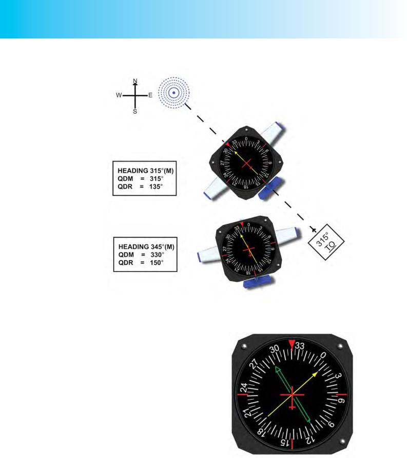
Figure 16.10 depicts a further example of the use of an RBS. In Figure 16.10, an aircraft on a heading of 325° (M) has its RBS rotated to indicate that heading, and, thus, the ADF needle indicates directly the QDM to the Haverford West NDB. The QDM is 008° (M). The bearing from the beacon, the radial or QDR, is 188º (M).
Figure 16.10 An aircraft on heading 325º, with the ADF display showing a TO bearing of 008º, and a FROM bearing (radial) of 188º. The RBS of the ADF display is aligned with the DI and therefore reads the QDM directly.
The Radio Magnetic Indicator.
An ADF display which incorporates a Radio Magnetic Indicator is the easiest of ADF displays for the pilot to interpret. The Radio Magnetic Indicator (RMI) consists of a standard ADF receiver but with the ADF needle combined with a DI compass card which always shows the aircraft’s heading with respect to Magnetic North. The RMI, then, interprets both radio and magnetic inputs to provide continuous heading, and bearing information.
The north-indicating compass card behind the ADF needle is similar to a Direction Indicator, in that it is a gyroscopic device which indicates North by virtue of the spatial rigidity of its gyroscope. However, unlike the DI, the RMI does not need to be periodically aligned with the magnetic compass. The RMI’s gyro is connected to a remotely located magnetic compass and is automatically fed directional signals which keep the RMI aligned with Magnetic North, as the aircraft changes direction.
A single-needle RMI looks exactly like the instrument at Figure 16.10, except that it will not have a heading knob. The compass card of the RMI does not need to be reset; the RMI will, at all times, indicate the present magnetic heading of the aircraft as well as the magnetic bearing to reach the NDB, the QDM. (See Figure 16.11.)
Of course, it is the head of the RMI needle which indicates the QDM; the tail of the needle will indicated the magnetic bearing from the NDB, the radial or QDR. The QDR information from an RMI, then, gives the pilot an immediate indication of the position line (or radial) from the NDB along which his aircraft is situated.
The magnetic
bearing from the aircraft to
the beacon
is known as the QDM. The magnetic bearing from the beacon to the aircraft is known as the radial or QDR.
The head
of the RMI needle always
gives a direct
reading of the QDM, while the tail indicates the radial or QDR.
287
Order: 6026
Customer: Oleg Ostapenko E-mail: ostapenko2002@yahoo.com
Customer: Oleg Ostapenko E-mail: ostapenko2002@yahoo.com
CHAPTER 16: AUTOMATIC DIRECTION FINDING (ADF)
Figure 16.11 Intercepting an NDB radial to track to the NDB on a heading of 315°(M), using an ADF fitted with an RMI.
Twin-needle Radio Magnetic Indicator.
You may fly in aircraft which are fitted with a twin-needle RMI as depicted in
Figure 16.12.
In Figure 16.12, the broad green needle is an ADF indicator, indicating a QDM to an NDB of 290° (M) while the narrow yellow needle is a VOR indicator (see Chapter 17), pointing towards a VOR beacon, for which the QDM is 010°(M). This twin-needle indication permits bearings FROM two different beacons to be taken, and is, therefore, particularly useful in fixing the location of an aircraft.
Figure 16.12 A twin - needle RMI with ADF and VOR indicators.
288
ID: 3658
Customer: Oleg Ostapenko E-mail: ostapenko2002@yahoo.com
Customer: Oleg Ostapenko E-mail: ostapenko2002@yahoo.com
CHAPTER 16: AUTOMATIC DIRECTION FINDING (ADF)
Interpreting ADF Indications.
The interpretation of ADF indications is direct and straightforward when the instrument is equipped with an RMI. However, RMIs are expensive to acquire, and many club aircraft will be fitted with ADFs which incorporate only an RBI, or, at best, an RBS. Interpreting the RBI requires some mental arithmetic agility from the pilot; but if you learn to track NDBs successfully and effectively using an RBI, flying with an RMI should present you with no difficulty at all.
The CD-ROM from OAAmedia devoted to the IMC Rating (‘The IMC Rating and Instrument Flying’) will teach you all you need to know about intercepting NDB radials and tracking to and from NDBs, using an RBI.
The most fundamental concept to bear in mind when considering how ADF can be used to assist you in navigating is that the ADF needle always points to the NDB to which the ADF receiver is tuned.
An ADF
needle always points to the
NDB to which
the ADF receiver is tuned.
NAVIGATING USING THE ADF.
By implication, then, one of the most basic and useful ADF applications, in navigation, is to be able to fly directly towards an NDB which is located at a pilot’s airfield of destination. However, in order to ensure that his ADF equipment will enable him to carry out this most basic of radio - navigation operations, the pilot must:
•Switch on the ADF receiver and select the correct frequency for the NDB beacon he wishes to fly towards.
•Confirm that the NDB is indeed the beacon he requires by checking, with the receiver set to ‘ANT’ (antenna), that the NDB’s identifying morse code signal is the one he expects.
•Reselect ADF and check that the ADF needle is responding sensibly.
Having carried out these basic actions, the pilot can be confident that the ADF needle is pointing to the correct NDB at the destination airfield.
Homing
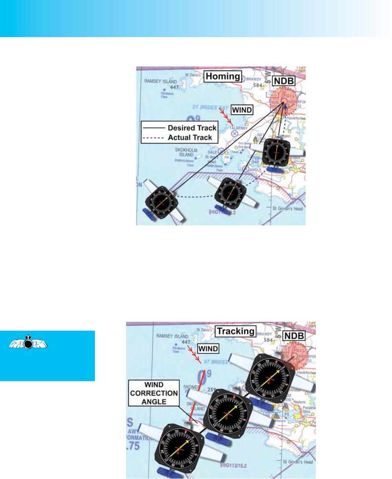
Homing towards an NDB refers to a procedure whereby the pilot flies towards the NDB by maintaining the head of the ADF needle at the top of the ADF display, in the 12 o’ clock position. If there is no wind, the pilot will fly directly to the NDB in a straight line. However, if there is a crosswind component, the wind will cause the aircraft to drift, and the pilot will constantly need to change his heading in order to keep the needle in the 12 o’ clock position. In this situation, the aircraft will follow a curved path to the NDB, as depicted in Figure 16.13. This is called homing.
After tuning
your ADF to the desired
NDB, always
confirm that it is the NDB you require by checking its morse identification code.
289
Order: 6026
Customer: Oleg Ostapenko E-mail: ostapenko2002@yahoo.com
Customer: Oleg Ostapenko E-mail: ostapenko2002@yahoo.com
CHAPTER 16: AUTOMATIC DIRECTION FINDING (ADF)
Figure 16.13 Homing towards a beacon.
Although homing eventually brings the aircraft to its destination, it constitutes poor piloting and poor airmanship. Homing would be unacceptable for IFR navigation, for instance, because the aircraft would stray from its assigned track.
Tracking.
The correct way to fly towards an NDB is to track towards it in the same way that you would maintain a desired track using visual navigation techniques. Consequently, again as in visual navigation, you must assess the drift and compensate for it by applying the appropriate wind correction angle. (See Figure 16.14.)
In order to
track correctly to an NDB,
a pilot needs to apply the appropriate wind correction angle.
Figure 16.14 Tracking directly towards an NDB, compensating correctly for drift, and maintaining a constant QDM, with a relative bearing of 030° on the RBI.
290
ID: 3658
Customer: Oleg Ostapenko E-mail: ostapenko2002@yahoo.com
Customer: Oleg Ostapenko E-mail: ostapenko2002@yahoo.com
CHAPTER 16: AUTOMATIC DIRECTION FINDING (ADF)
Do not attempt to follow a moving ADF needle; hold your heading and correct for drift systematically. (See also the OAAmedia CD-ROM: ‘The IMC Rating and
Instrument Flying’.)
Maintaining a Desired Track to an NDB in a Crosswind.
Let us assume that you wish to fly directly towards an NDB at your destination airfield, on a QDM of 060°(M). Your ADF display is an RBI so the ADF compass card does not rotate but indicates only the relative bearing of the NDB with respect to your aircraft’s nose. You do, however, have a serviceable Direction Indicator (DI), and so you must use the RBI and the DI together to maintain your desired
track.
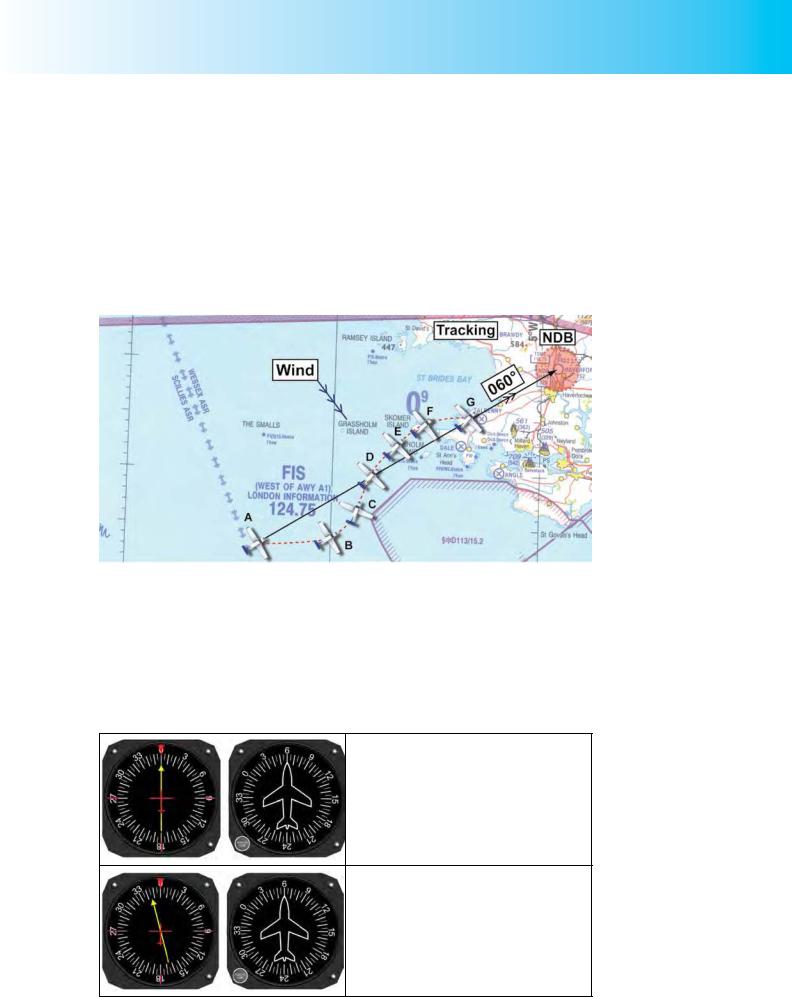
Figure 16.15 Bracketing a track of 060° to an NDB.
Figure 16.15 depicts your aircraft being blown off track by a cross wind, then regaining it and, finally, tracking 060° to the NDB with the correct wind correction angle applied. This action is called bracketing.
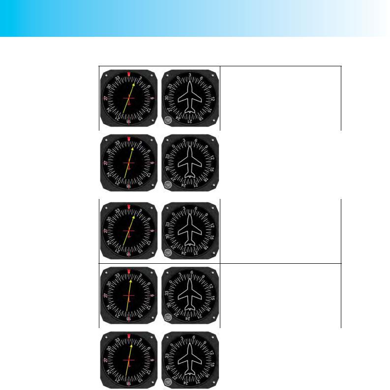
The following table depicts your RBI and DI displays for the situation in Figure 16.15 and describes your actions at the various positions (A, B, C etc,) of your aircraft as you regain track. Remember, the main principle of ADF tracking: the ADF needle always points at the NDB. Note, too, that to regain track, you always
A turn the aircraft towards the head of the ADF needle.
B
Order: 6026
Customer: Oleg Ostapenko E-mail: ostapenko2002@yahoo.com
Customer: Oleg Ostapenko E-mail: ostapenko2002@yahoo.com
CHAPTER 16: AUTOMATIC DIRECTION FINDING (ADF)
C Position C. Now, heading 030°(M), you close again with the desired track to the NDB of 060°(M). With your RBI indicating 020°, you see that you are momentarily on the 050° radial to the NDB (030° + 020° = 050° QDM) still to the left, so you hold your heading of 030°(M).
D |
|
|
Position D. As the RBI needle falls towards |
|
|
|
030° you know that you are once again |
|
|
|
about to intercept the 060° radial to the NDB. |
|
|
|
So, aware that the wind is from the left, you |
|
|
|
gently turn right onto a heading of 045°(M), |
|
|
|
hoping that this heading will keep you on |
|
|
|
track. The RBI needle rises to indicate a |
|
|
|
relative bearing of 015° so confirming that |
|
|
|
you are again on the 060° radial to the NDB; |
|
|
|
so you are hopeful that you have got it right. |
|
|
|
|
|
|
|
|
E
Position E. If the 15º Wind Correction Angle (WCA) had been correct, then the ADF needle would have continued to indicate a relative bearing of 015º while you maintained a heading of 045º(M) and the aircraft would have remained on the 060° radial to the NDB. However, the WCA is too great, so the aircraft has moved to the left of the QDM radial by 5° onto a QDM of 065°, with the RBI indicating a relative bearing of 020°.
F
Position F. Assessing that you have overestimated the WCA, you turn right 10º onto a heading of 055º magnetic, judging that, on this heading, the wind will cause you to drift back onto the 060° radial to the NDB. The RBI needle will still initially indicate something greater than 005º, say 008º, but will move towards 005º as you close with the required radial track. (055° + 05° = 060°, the desired QDM.)
G |
|
|
Position G. With a heading of 055°(M), and |
|
the RBI needle indicating a relative bearing |
||
|
|
|
of 005°, you know that you are back on the |
|
|
|
060° radial to the NDB. At this point, you turn |
|
|
|
left 5° onto a heading of 050°(M). Seeing |
|
|
|
that the RBI needle is now indicating 010° |
|
|
|
and remains there, you know that you are |
|
|
|
tracking to the NDB on a QDM of 060°(M) |
|
|
|
and have correctly applied an accurate wind |
|
|
|
correction angle of 10° |
|
|
|
|
Note: A useful trick is to imagine the ADF needle superimposed on the DI to give the QDM - this is explained in the following pages.
ADF and Radio-Navigation.
The primary aim of this book is to prepare you for the PPL theoretical knowledge examinations; it is not a flying instructional manual, and does not aim to teach airborne radio-navigation techniques. However, the above account of the basic considerations of tracking towards an NDB includes the fundamental principles of ADF navigation. Always remember that:
•The ADF needle always points at the NDB.
292
ID: 3658
Customer: Oleg Ostapenko E-mail: ostapenko2002@yahoo.com
Customer: Oleg Ostapenko E-mail: ostapenko2002@yahoo.com
CHAPTER 16: AUTOMATIC DIRECTION FINDING (ADF)
•The pilot must always turn towards the head of the ADF needle in order to intercept, or regain, any desired QDM. This rule applies whether flying inbound to, or outbound from, an NDB.
If your ADF display is an RBI, you will need to use the RBI in conjunction with the DI and use basic mental arithmetic in order to work out the magnetic bearing to the NDB (the QDM), or the magnetic bearing from the NDB (the QDR). For instance, as you have just seen in the example on how to regain a desired QDM, the QDM at any point is given by the aircraft’s magnetic heading, read from the DI, plus the relative bearing to the NDB indicated by the RBI needle, in terms of degrees right or left of the aircraft’s nose. If this calculation gives a figure of greater than 360°, subtract 360° from the figure to get the QDM.
If your aircraft has an RMI, the QDM to any NDB you are tuned to, and its reciprocal the QDR, are indicated constantly by the head and tail respectively of the RBI needle.
In the navigational element of the airborne skills test for the JAR-FCL PPL, the candidate is required, amongst other things, to determine his position, and to intercept and maintain given tracks or radials using nominated radio navigation aids. Your flying instructor will teach you these skills; but, if you are using ADF, the theory that you have learned in this chapter should help you acquire the corresponding flying skills.
You have learned the fundamental considerations of maintaining a selected track to an NDB. As your flying instructor will teach you, the same fundamental principles are involved in tracking away from an NDB. Furthermore, the principles involved in regaining a desired NDB radial from which your aircraft has drifted away, are the same as the principles employed in intercepting a desired NDB radial. Let us take a brief look at this latter situation.
Intercepting a Desired NDB Radial.
At some point during your PPL navigational skills test, usually after the first leg, you will probably be asked to track towards an NDB or VOR beacon on a nominated QDM, rather than just fly directly towards the beacon as we have described above. In other words, you will know where you want to go but you will have to work out how to get there using a specific route; therefore you have to intercept a nominated beacon radial, and track towards it on the correct QDM.
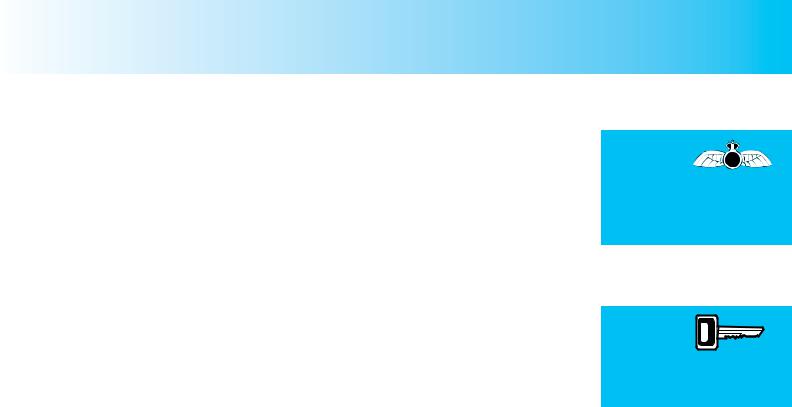
Let us look at an example of how to intercept a desired NDB radial and track towards it, using an RBI. The example is illustrated in Figure 16.16.
In Figure 16.16, at Position A, the aircraft is heading 015°(M), with an RBI indicating a relative bearing of 340°, which gives a bearing 355°(M) with respect to the NDB.
However, let us assume that you wish to track to the NDB on a QDM of 330°(M).
You must try to visualise where the track of the desired QDM lies in relation to your present heading, and to work out an intercept course. It is easy from Figure 16.16 to see exactly which way you need to turn and the approximate track which will intercept the desired QDM, but you will not be able to draw diagrams in the cockpit, so you need a method of visualising the air situation, using what means you have at your disposal, namely the RBI and the DI.
An aircraft must always be turned
towards the
head of the ADF needle in order to intercept or regain any desired QDM.
With an RBI,
the QDM is given by
the aircraft’s
magnetic heading plus the relative bearing.
293
Order: 6026
Customer: Oleg Ostapenko E-mail: ostapenko2002@yahoo.com
Customer: Oleg Ostapenko E-mail: ostapenko2002@yahoo.com
CHAPTER 16: AUTOMATIC DIRECTION FINDING (ADF)
You should, therefore, mentally transfer the RBI needle to the face of the DI; the head of the imagined needle points towards the NDB, and your aircraft sits on the needle’s tail, aligned just as the small aircraft in the centre of the ADF instrument is aligned. Figure 16.16 indicates this situation, for the aircraft at Position A, by the yellow dotted line on the DI.
When
intercepting an NDB radial, the
head of the ADF needle will always fall.
If your ADF
display is an RBI, the QDM to any NDB is
given by the sum of aircraft’s Magnetic Heading and the Relative Bearing. If this sum gives an answer greater than 360°, subtract 360° to obtain the QDM.
Figure 16.16 Intercepting a desired NDB radial using an RBI.
Now, you must visualise another imaginary RBI needle (shown as red in Figure 16.16) sitting on the DI face with a small aircraft on its tail pointing inbound to the NDB on the desired QDM of 330° (M). Comparing the relative positions of the imaginary needles and aircraft, it is relatively easy to see that a left turn will be required to maintain the QDM once it is reached. The situation, for the aircraft in Position A, is shown on the DI in Figure 16.16.
The next principle to grasp when intercepting an NDB radial is that the head of the needle will always fall; that is, it will move further towards the 6 o’clock position on the RBI (180° Relative Bearing). But you now need to determine what the RBI will indicate when you arrive at the interception point with the 330° QDM.
When working with an RBI, the QDM, for any aircraft position, with respect to any NDB to which you are tuned, is given by the DI heading plus the relative bearing indicated by the RBI.
QDM = (Magnetic Heading + Relative Bearing)
Therefore, in Position A, the QDM is (015° + 340°) = 355° (M).
(You could of course reason that 340° indicated on the RBI is 20° left of your magnetic heading of 015°(M), which also gives 355°(M).)
294
ID: 3658
Customer: Oleg Ostapenko E-mail: ostapenko2002@yahoo.com
Customer: Oleg Ostapenko E-mail: ostapenko2002@yahoo.com
CHAPTER 16: AUTOMATIC DIRECTION FINDING (ADF)
In Position B, the QDM is (015° + 330°) = 345° (M). Consequently, if you hold your heading of 015°(M), which will give you a reasonable interception angle of 45°, the desired QDM of 330°(M) is given by the expression:
330°(M) = 015° + Relative Bearing.
It is fairly easy to work out, then, that you will arrive at the desired QDM of 330°(M) when the RBI indicates 315°. This is the position indicated by Position C, in Figure 16.16.
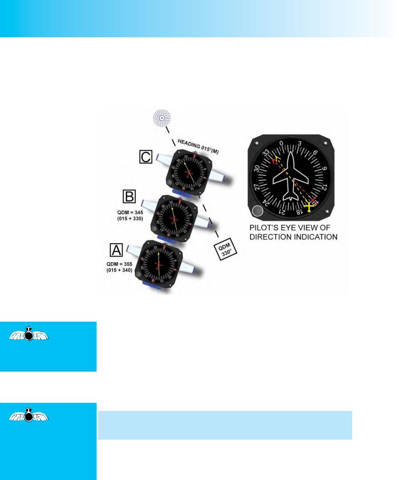
As we have mentioned, the ADF needle will continue to fall (to the left) as the required QDM of 330°(M) is approached. It is appropriate to begin turning onto the QDM when you are 5° short of it, so, when the relative bearing is 320°, initiate a medium turn to the left (about 20° angle of bank should be appropriate at light aircraft speeds), to head 330°(M). As you apply bank, you will probably find that the ADF needle will fall a little further because of the phenomenon of “dip” but ignore this and roll out on the heading required. When the aircraft is steady, wings level, on 330° (M), as indicated by the DI, check the RBI. If the RBI needle is indicating 000°, (See Figure 16.17), you will have judged your turn perfectly; if it is not, then you will have to make an adjustment.
Figure 16.17 Established on a QDM of 330°(M).
It is, of course, very difficult to achieve perfection with an RBI, and so when the wings are level you will usually find that the relative bearing is not 000° but three or four degrees left or right. There will also be the wind to contend with. You will, therefore, almost certainly have to make adjustments to your heading similar to those described previously.
Your flying instructor will teach you the ADF tracking procedures required for the PPL navigation skills test. If, after gaining your PPL, you wish to gain an IMC Rating, OAAmedia
produce an interactive multimedia CD-ROM covering the whole of the IMC theoretical knowledge and practical flying course, entitled ‘IMC Rating & Instrument Flying’.
295

Order: 6026
Customer: Oleg Ostapenko E-mail: ostapenko2002@yahoo.com
Customer: Oleg Ostapenko E-mail: ostapenko2002@yahoo.com
CHAPTER 16: AUTOMATIC DIRECTION FINDING (ADF)
The True Bearing from
the beacon to the aircraft is
known as the QTE.
USES OF AUTOMATIC DIRECTION FINDING.
Although Automatic Direction Finding (ADF) is the oldest extant pilot-interpreted radio-navigation system, it still has numerous uses in aviation. We have covered NDB tracking in some detail in this chapter, other uses are:
Position Fixing.
Taking bearings from two NDBs enables a pilot to fix his position en route. NDBs on aeronautical charts do not have compass roses around them; neither is there any indication of Magnetic North. So, when taking a bearing from an NDB, based on determining what NDB radial the aircraft is positioned on, the pilot must establish the true bearing of the radial from the NDB, using the lines of longitude and a navigational protractor. Therefore, if a bearing indication shows that your aircraft is on, say, the 150° radial from an NDB, this radial, having been established from instruments which indicate magnetic bearings, must be converted into a radial expressed in degrees true. 150° (Magnetic) would be 146° (True) if the local magnetic variation at the aircraft were 4° West. (Variation West, Magnetic Best.) The pilot, then, would draw a line from the NDB of 146° (True) in order to represent the 150° (M) radial. The true bearing from a beacon or aerodrome is known as the QTE.
Airways NDBs.
A very small number of NDBs are still used as waypoints on airways, but have mostly been replaced by the more accurate and longer-range VOR/DME. Area navigation systems (INAS and GPS) have also made them largely redundant for IFR navigation.
Holding.
NDBs are still used for aircraft to hold awaiting clearance to commence an instrument approach procedure; the race-track holding pattern is flown at a FL or altitude assigned by Air Traffic Control.
Instrument Approaches.
NDBs are used in NDB approach procedures. The NDB approach is a non-precision approach, that is, it gives no electronic glidepath information. Because of this, and the lower accuracy tolerances of the NDB, the weather minima (cloudbase and visibility) are higher than those of other instrument approach aids.
NDBs are also used as locators in conjunction with Instrument Landing System (ILS) approaches, both as the holding fix and the Initial Approach Fix for the start of the procedure.
FACTORS AFFECTING ACCURACY.
Accuracy.
The best guaranteed accuracy of NDBs is ±5°.
Designated Operational Coverage.
The designated operational coverage (DOC) of an NDB defines the maximum range from an NDB at which a pilot will receive the required level of bearing accuracy of ±5°, by day only. DOCs are typically between 15 and 50 nms. Information on the DOC of NDBs is contained in the United Kingdom, Aeronautical Information Publication (AIP) in the GEN and ENR sections.
296