

3 Description of laboratory research facility and methodology of measurements
Devices and outfits: Set of inductances, set of capacities, set of resistances, voltmeter, sound generator ГЗ-36.
In a given work we study capacitor, inductor and resistor voltages dependencies on external driving EMF frequency Ω. Magnitudes of R, C, L and amplitude of driving EMF Em remain constant during the work.
F
Figure 14 –
Laboratory research
facility's scheme.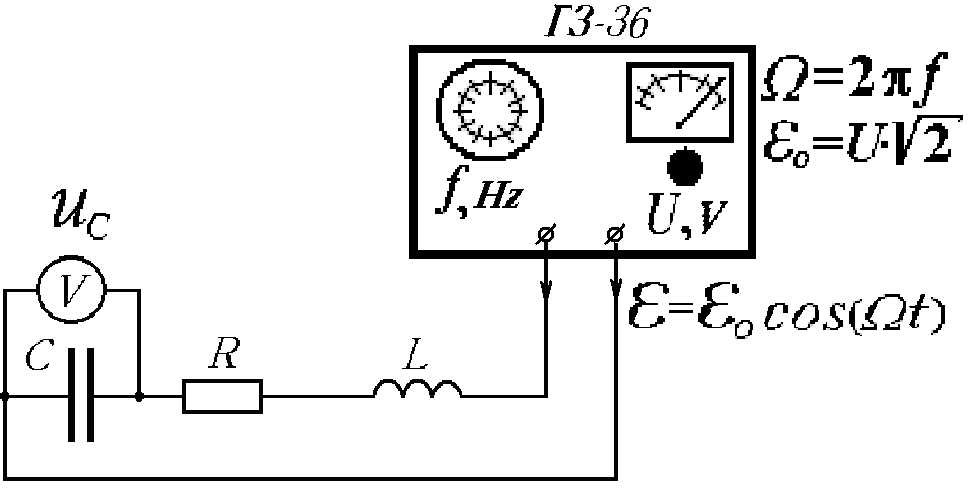
![]() ,
,
![]()
Obviously that effective current and EMF related as
![]()
If we’ll change the frequency of generator then phase lag between current and EMF also will be changed as the reactance changes. As it seen from (63), (64) and Fig.13, at low frequencies uL < uC and uL > uC at high. Obviously that there will be some frequencies ΩC = ΩL at which uC = uL and get maximum.
Using indexes of voltmeter, switched to capacitor or inductance coil we can find frequency ΩC or ΩL, which, in case of high enough quality, will be equal to resonance frequency.
So, in this work we can plot:
Effective voltage on capacitor UC versus driving EMF frequency Ω = 2πν, where ν determined with ГЗ-36 limb;
Effective current I = 2πνCUC in a circuit versus Ω;
Effective voltage on inductor UL = IΩL, or substituting I and Ω, UL = 4π2ν2CUCL. Inductance L can be determined from the match of driving and natural frequencies of the circuit at resonance, i.e.:
![]()
4 Data processing (see laboratory work № 4-1).
5 Work execution order and experimental data analysis
1. Turn on ГЗ-36. Wait 5 minutes till it warms up.
2. Using potentiometer “Рег.выхода” set generator output voltage 1.5 – 3 V. This voltage should remain unchangeable during the work.
3. Set fixed value of resistance R on the set of resistances. Fix value of capacity C.
4. Set 20 Hz on generator and fix voltage on a voltmeter (is equal to voltage on capacitor). By changing the frequency GEN and look after voltmeter data let's pass all frequency range from 20 to 200 Hz.
Change in 10 times the frequency band by «Множитель» switcher if there no resonance voltmeter data increasing will be found and so on until the frequency range at which resonance frequency RES situation will be determined. At this frequency RES the voltmeter reading will be maximal UC =UC RES.
Note: generator scale gives frequencies GEN in Hz, whereas Ω=2πν in rad/s.
5. In established frequency range do 5-7 measurements of effective values UC for GEN < RES and 5-7 measurements – for GEN > RES.
6. By obtained data of GEN calculate values of cyclic frequency ΩGEN = 2πνGEN. By obtained data of effective values UC for given capacity C calculate values of amplitude of current from definition of amplitude of voltage on capacitor UmC=ImXC. and relation between the amplitude of voltage and its effective value UmC=UC2. Read calculated data to the measurement table.
7. By
resonance frequency ΩRES
calculate inductance of coil from
![]() .
.
8. Plot a graphs UC = f(Ω) and Im = f(Ω) as a final result of the work.
9.
Calculate quality of circuit
![]() and resistance
from
and resistance
from
![]() .
.
10. Write values Q, ΩRES, L and R in final results.