

2.2 Parametric resonance. Standing waves.
In order to determine vibrator’s frequency we use standing waves that appear in tense thread connected to vibrator. Oscillations of any oscillatory system can be made forced by driving any of its parameters. The resonance that will appear in this case is called the parametric resonance.
L
Figure
14– Standing wave in thread: a) at initial moment; b) over half of a
period of vibrator. c) over period of
vibrator
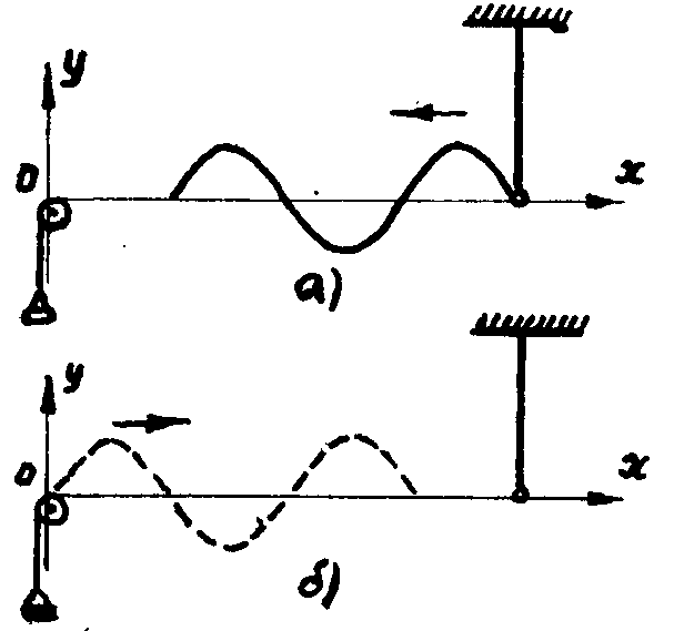
Figure 15 –
Traveling
elastic wave propagation in a thread: a) incident wave; b) reflected wave .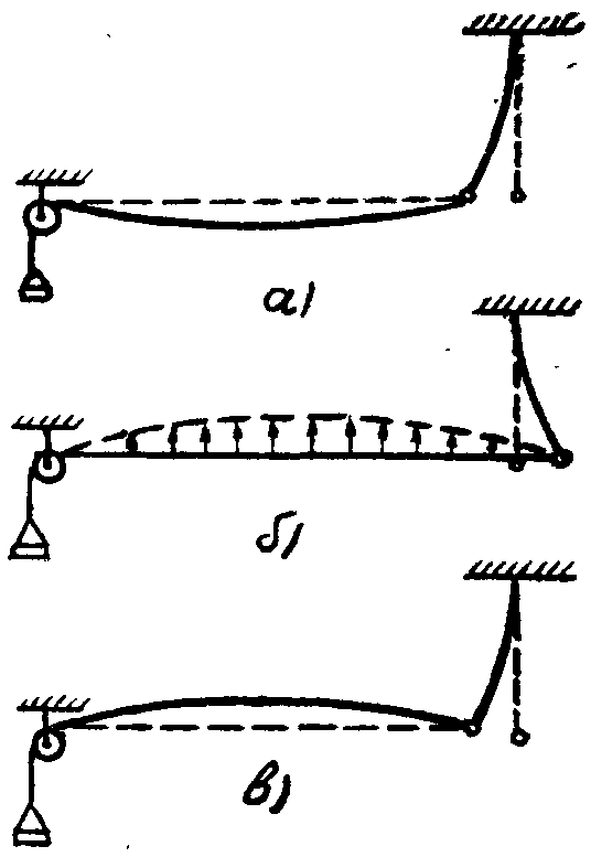
Any system which is able to oscillate will perform natural oscillations under the action of random external affection. If the frequency of this parametric affection is double the system’s natural frequency the oscillations become forced (holds the conditions of parametric resonance). Same phenomena can be achieved in electric circuit by external alternation of capacitance or inductance. Work of parametric generators and amplifiers is based on parametric resonance phenomenon.
Oscillations of vibrator produce elastic wave, propagating along the thread with frequency ω and amplitude A. All points of thread will perform undamped oscillations if thread is not quite long and dissipations of energy are small.
Let’s set O (point of pulley and thread connection) as origin of coordinates. A wave, which has reached this point, will be reflected back. Thus we’ll have two waves travelling in opposite directions:
|
ξ1 = A cos(ωt + kx) |
(68) |
|
ξ2 = A cos(ωt – kx+π) |
(69) |
All points of a thread will be behind vibrator’s oscillations as much, as smaller will be x in chosen coordinate system (Fig. 15). That is why equation (68) is equation of incident plane travelling wave, and (69) – equation of reflected wave. Minus sign before kx in reflected wave equation means that phase of oscillations of each thread’s point in reflected wave as smaller as far this point is from origin of coordinates. Besides, as point O immovable, phase of reflected wave will be deferent at that point from phase of incident wave on π.
The result of superposition of incident and reflected waves will be complex oscillations of all points of thread under the law:
ξ = ξ1
+
ξ2
= 2A
cos![]()
cos
cos![]() ,
,
|
or
ξ = 2Acos(kx
–
|
(70) |
Thus, we’ve
obtain equation of steady state standing wave in a thread. A time
independent expression ASW(x)=|2A
cos(kx–![]() )|
represents theamplitude
of standing wave.
As it seen, the amplitude varies under harmonic law with respect to
distance x
from
origin of coordinates. For points at which
)|
represents theamplitude
of standing wave.
As it seen, the amplitude varies under harmonic law with respect to
distance x
from
origin of coordinates. For points at which
|
kx
–
|
(71) |
amplitude gets maximal value equal to ASW(xAN)=2A. These points called antinodes or wave crests. From (71) we can obtaine coordinates of antinodes:
|
xAN
=
(2n
+
1)
|
(72) |
Points, at which
|
kx
-
|
(73) |
do not oscillate and ASW(xN)= 0. These points called nodes of standing wave. The nodes appear in points at which incident and reflected waves are in antiphase. As it follows from (73), the coordinates of nodes are
|
xN
= 2n
|
(74) |
Distance between two nodes or antinodes called standing wavelength. That is why
λST
=
![]() λ.
λ.
Since there are nodes at both fixed ends of a thread, so, thread’s length l must contain integer number of standing wavelengths
l =
n
λST
= n![]() .
.
On a Fig. 16 shown appearance of standing wave by reflection, with phase, changed on π. Solid line represents displacement of thread’s points produced by incident wave, dashed line – by reflected wave. The resultant displacement represented by bold line. The figure shows moment at which incident wave come to point O with non-zero phase.
T
Figure
16– Standing wave as superposition of incident and reflected
waves.