

Broadband Packet Switching Technologies
.pdf258 CLOS-NETWORK SWITCHES
10.2 A SUBOPTIMAL STRAIGHT MATCHING METHOD FOR DYNAMIC ROUTING
A crucial requirement on the routing or scheduling algorithm is that it must run extremely fast, because cells have to be assigned paths on a slot-by-slot basis. A distributed routing algorithm is considered, which is suboptimal in performance, but runs fast and is simple to implement in hardware.
Let us consider a particular input module, say the first one. It may have a total of n cells arriving at a time, and the assignment hardware has to finish assigning these n cells within some prescribed duration less than a time slot. We further divide into k mini-slots of length rk, and now focus on the assignment operation inside a minislot. During every mini-slot, the Bj of a specific output module is made available for assignment to an input module Ai , i.e., matching of Ai with Bj. Note that there are at most n matches needed in each mini-slot, as there are at most n input cells at an input module. While Ai is matched against Bj, simultaneously Aiq1mod k is matched against Bjq1mod k , and so on, thereby permitting parallel assignments. In the
next mini-slot, each Bj is moved on to the next Ai Ži.e., Aiq1mod k . in a cyclic manner Žsee Fig. 10.5.. Since there are k output modules, a total of k
mini-slots are necessary in each slot.
Since the switch architecture uses output queuing, it has the best possible delay throughput performance w5x. Consequently, we only need to compute the lost-cell probability. There are two sources of cell loss in the switch. First, cells are dropped if too many simultaneously arrive destined for an output group Žthe loss due to knockout.. Second, additional cells are dropped if the distributed, suboptimal routing algorithm cannot schedule a path through the switch. The analysis of this scheduling loss is complex and can be found in w5x. Here we just highlight the main results for the switch configuration without middle-stage trunking.
Fig. 10.5 Parallel assignments in a cyclic manner from mini-slot to mini-slot.
THE ATLANTA SWITCH |
259 |
Assuming the cells have independent, uniform destination address distributions, the loss probability increases from one mini-slot to the next as more and more cells are assigned routing paths in a given time slot. Upper bounds on the lost-cell probability for the worst case input output pairs Žthe last to be scheduled in a time slot. are derived in w5x.
For a group size n s 16, Figure 6.11 shows the worst case cell loss probability as a function of m, the number of simultaneous cells accepted, under various loads. The loss due to knockout in Figure 6.11 is for the worst case Žlast. input, and is given by Ža generalization of Ž4. in w16x.
m |
Ž np. |
k |
yn p |
|
Prwcell loss for worst case inputx s 1 y Ý |
|
e |
. |
|
|
|
|
||
ks0 |
k! |
|||
|
|
|
|
|
Note that m s 35 is large enough to keep the cell loss probability below 10y6 for an 80% load, compared to a value of m s 34 required by the knockout loss alone. Each increase in m results in approximately an order of magnitude decrease in the lost-cell probability, and both sources of loss can be made negligible small. Since the knockout loss and knockout q scheduling loss curves are so close to each other, an optimal routing algorithm would not provide much improvement; the lost-cell probability cannot be less than that indicated by the generalized knockout principle. In addition, middle-stage trunking can provide only marginal improvement over the results presented in Figure 6.11.
10.3THE ATLANTA SWITCH
The ATLANTA switch architecture was developed by Bell Labs w10x. The switch fabric is a three-stage multimodule memory space memory ŽMSM. arrangement. The MSM configuration uses buffers in the input and output stages, while the second stage is bufferless. A simple distributed self-routing algorithm is used to dispatch cells from the input to the output stage. Although cells are routed individually and multiple paths are provided from each input to each output, cell sequence is preserved due to its bufferless second stage. Selective backpressure is used from the output to the input buffers in the fabric, so the required buffers in the output stage are also relatively small.
The ATLANTA architecture provides optimal support of multicast traffic. Cells belonging to a multicast virtual circuit are always replicated according to a minimum multicast tree, that is, they are replicated as far downstream as possible in the switch; this minimizes the amount of resources required to sustain the expansion in traffic volume internally to the switch due to multicasting. A single copy of a multicast cell is locally stored in each buffer, and replicated Žif necessary. only when the cell is sent to the following stage in the switch or to its desired destinations.
260 CLOS-NETWORK SWITCHES
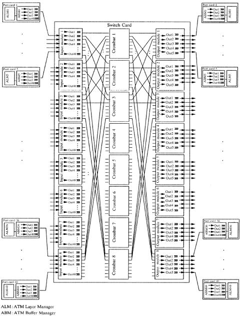
Fig. 10.6 Schematic configuration of a 40 40 multistage ATLANTA switch. Ž 1997 IEEE..
THE ATLANTA SWITCH |
261 |
In the following, we describe the operation of the MSM switch fabric with reference to the specific 40 40 configuration shown in Figure 10.6. The operation of configurations of other sizes can be easily inferred from this discussion.
10.3.1Basic Architecture
The MSM configuration is based on three main principles:
By using buffers in the first stage to store cells that cannot be routed to the output buffers at a given time, the number of paths necessary for nonblocking behavior can be greatly reduced.
By using a bufferless center stage, cells belonging to the same virtual circuit can be routed individually without affecting the cell sequence.
By using selective backpressure from the output buffers to the input buffers, buffers can be located where it is most economical.
Under these design principles in the ATLANTA switch, a memory switch is used to implement the switching modules in the first and the third stages, while crossbars are implemented in the second stage. Each module in the first and third stages must be connected to all crossbars. All interconnection lines between adjacent stages have the same rate as the input and output ports. To realize nonblocking in the MSM configuration, it is well known that its internal capacity must be higher than the aggregate capacity of the input ports. We call this expansion. The required expansion is achieved by connecting fewer than eight ports to each input and output module. In the 40 40 configuration of Figure 10.6, five ports are connected to each edge module for an expansion factor of 5 : 8. The expansion ratio is 1.6 Žs 8r5.. Each module in the first stage maintains 40 groups of queues; each group corresponds to one of the output ports in the switch. Each module in the third stage manages a number of groups equal to the number of ports connected to that module Žin this case five..
10.3.2Distributed and Random Arbitration
In order to minimize the required expansion, an efficient routing algorithm is necessary to route cells from the input to the output modules. Intuitively, the idea is that the fabric is nonblocking as long as the equivalent service capacity Ži.e., the maximum switching capacity provided by the expansion and the routing algorithm. in the input queues is higher than the aggregate input capacity of those queues. A practical constraint for such a system to be cost-effective is that the routing algorithm must be fully distributed and independently run by each input module. Below is the novel concurrent dispatching algorithm that is used in the ATLANTA architecture.
262 CLOS-NETWORK SWITCHES
The concurrent dispatching works as follows. In each time slot, each input module in the first stage selects up to eight cells to be served in that time slot. The selection process over the 40 groups of queues uses a two-level weighted-round-robin mechanism.1 Once the cells are selected, each input module sends up to eight bids to the crossbars, one for each crossbar. A bid contains the desired destination and service priority of one of the selected cells. Since there is no coordination among the input modules, a crossbar can receive more than one bid at a time for the same output module. In case of conflict between two or more bids, the crossbar selects one as the winning bid. In selecting the winning bid, and generally in determining whether a bid is successful or not, the crossbar takes into account whether or not the specific queue in the output module requested by each bid has available buffer space Žthe third-stage modules continuously send backpressure information to the crossbars informing them of the availability of buffers for each queue., and never declares successful a bid that requests a queue with no available buffer space. Then the crossbar sends a feedback signal to the input modules, informing each module whether or not the bid was successful, and in the latter case whether the bid was unsuccessful because of lost contention in the crossbar or because of selective backpressure from the output modules.
If the bid was successful, in the following time slot the input module transmits the corresponding cell through the crossbar; in the same time slot, the input module also selects another cell and initiates a new bidding process for it on that crossbar. If the bid was unsuccessful because of lost contention in the crossbar, the input module again sends that same bid to the crossbar in the following time slot. If the bid was unsuccessful because of backpressure from the output modules, the input module selects a different cell from the the buffer and initiates a bidding process for it in the following time slot.
10.3.3Multicasting
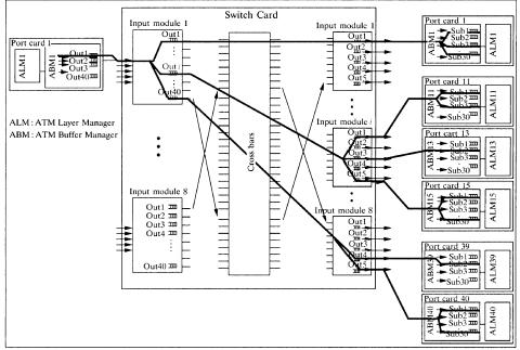
Multicast cells in the ATLANTA architecture are treated very similarly to unicast cells. They are always replicated as far downstream as possible in the switch. In the first stage, a multicast cell is replicated in only m1 copies, where m1 is the number of different modules in the third stage that the cell is destined for. Referring to the situation depicted in Figure 10.7, for example, cells belonging to connection V with the destinations highlighted in the figure would only be replicated three times in the input module. In particular, a cell that is destined to multiple ports in an output module is only queued in one of the corresponding queues. See Figure 10.7. Cells from connection V are only queued in the queues corresponding to ports 1, 11, 13, 15, 39, and 40. Then, a multicast cell is further replicated to the desired output ports in each module in the third stage.
1 Cells in each group are further classified into several categories of different service priority.
THE CONTINUOUS ROUND-ROBIN DISPATCHING SWITCH |
263 |
Fig. 10.7 Example of a multicast connection in a 40 40 ATLANTA switch with multistage fabric. The minimum multicast tree for cells of that multicast connection is highlighted. Ž 1997 IEEE..
In each edge module throughput the switch, only one copy is kept in memory for each multicast cell. A cell is replicated only when it is to be transmitted to the next stage. An appropriate destination bit map is stored in the cell header to control the replication through the fabric. The whole replication mechanism is therefore embedded in the self-routing structure of the switch.
10.4THE CONTINUOUS ROUND-ROBIN DISPATCHING SWITCH
The ATLANTA switch described in Section 10.3 is not able to achieve a high throughput unless the internal bandwidth is expanded, because contention at the second stage cannot be avoided. The relationship between the internal expansion ratio and switch size in the ATLANTA switch was analytically derived in w14x. To achieve 100% throughput by using the random dispatching scheme, the internal expansion ratio is set to about 1.6 when the switch size is large w10x. This makes it difficult to implement a high-speed switch in a cost-effective manner.
264 CLOS-NETWORK SWITCHES
It is a challenge to find a cost-effective dispatching scheme that is able to achieve a high throughput in Clos-network switches, without allocating any buffers in the second stage to avoid the out-of-sequence problem and without expanding the internal bandwidth.
A solution to the challenge was introduced in w14x, where a round-robin- based dispatching scheme, called the concurrent round-robin dispatching ŽCRRD. scheme, was proposed for a Clos-network switch. The basic idea of CRRD is to use the desynchronization effect w13x in the Clos-network switch. The desynchronization effect has been studied using simple scheduling algorithms as iSLIP w13, 11x and dual round-robin matching ŽDRRM. w1, 2x in an input-queued crossbar switch. CRRD provides high switch throughput without expanding the internal bandwidth, while the implementation is simple because only simple round-robin arbiters are employed. We showed that CRRD achieves 100% throughput under uniform traffic.
10.4.1Basic Architecture
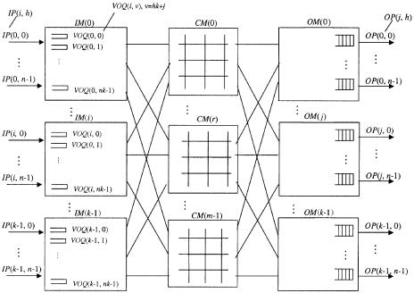
Figure 10.8 shows the CRRD switch. The terminology used in this section is as follows:
IM |
Input module at the first stage. |
CM |
Central module at the second stage. |
OM |
Output module at the third stage. |
nNumber of input ports Žoutput ports. in each IM ŽOM.
kNumber of IMs or OMs.
mNumber of CMs.
i IM number, where 0 F i F k y 1.
j |
OM number, where 0 F j F k y 1. |
hInput port ŽIP. or output port ŽOP. number in each IMrOM, respectively, where 0 F h F n y 1.
rCentral module ŽCM. number, where 0 F r F m y 1.
IMŽi. CMŽr . OMŽ j. IPŽi, h. OPŽ j, h. VOQŽi, ®.
ith IM. r th CM. jth OM.
hth input port at IMŽi.. hth output port at OMŽ j..
Virtual output queue ŽVOQ. at IMŽi. that stores cells
destined for OPŽ j, h., where ® s hk q j and 0 F ® F nk y 1.
GŽi, j.
LiŽi, r .
LcŽr, j.
VOQ group at IMŽi. that consists of n VOQŽi, j, h.s. Output link at IMŽi. that is connected to CMŽr . Output link at CMŽr . that is connected to OMŽ j..
THE CONTINUOUS ROUND-ROBIN DISPATCHING SWITCH |
265 |
Fig. 10.8 CRRD switch with virtual output queues in the input modules.
The first stage consists of k IMs, each of which is n m. The second stage consists of m bufferless CMs, each of which is k k. The third stage consists of k OMs, each of which is m n.
IMŽi. has nk VOQs to eliminate HOL blocking w10x. VOQŽi, ®. stores cells that go from IMŽi. to OPŽ j, h. at OMŽ j., where ® s hk q j. A VOQ can receive, at most, n cells from n IPs in each cell time slot. The HOL cell in each VOQ can be selected for transmission across the switch through CMŽr . in each time slot. This ensures that cells are transmitted from the same VOQ in sequence.
IMŽi. has m output links. An output link LiŽi, r ., is connected to CMŽr .. CMŽr . has k output links, denoted as LcŽr, j., and it is connected to k
OMs, denoted as OMŽ j..
OMŽ j. has n output ports, denoted as OPŽ j, h., and has an output buffer. Each output buffer receives at most m cells in one time slot, and each output port of an OM forwards one cell in a FIFO manner to the output line.
10.4.2Concurrent Round-Robin Dispatching Scheme
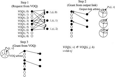
Figure 10.9 illustrates the detailed CRRD algorithm. To determine the matching between a request from VOQŽi, ®. and the output link LiŽi, r ., CRRD adopts an iterative matching within IMŽi.. An IM has m output link arbiters, each of which is associated with each output link, and each VOQ has a VOQ arbiter as shown in Figure 10.9.
266 CLOS-NETWORK SWITCHES
Fig. 10.9 CRRD scheme.
We consider two phases for dispatching from the first stage to the second stage. In phase 1, at most m VOQs are selected as candidates, and the selected VOQ is assigned to an IM output link. A request that is associated with this output link is sent from IM to CM. This matching between VOQs and output links is performed only within the IM. In phase 2, each selected VOQ that is associated with each IM output link sends a request from IM to CM. CMs respond with the arbitration results to IMs so that the matching between IMs and CMs can be done.
Phase 1: Matching within an IM
First iteration
Step 1: Each nonempty VOQ sends a request to every output link arbiter, each of which is associated with LiŽi, r ., where 0 F i F k y 1 and 0 F r F m y 1.
Step 2: Each output link LiŽi, r ., where 0 F i F k y 1 and 0 F r F m y 1, independently seeks a request among nk nonempty VOQs. Each output link arbiter associated with LiŽi, r . has its own pointer PLŽi, r ., where 0 F i F k y 1 and 0 F r F m y 1. The output link arbiter seeks one nonempty VOQ request from the PLŽi, r . in a RR fashion. Each output link arbiter sends the grant to a requesting
VOQ. Each VOQ has its own RR arbiter and one pointer PV Ži, ®., where 0 F ® F nk y 1, to choose one output link. The VOQ arbiter seeks one grant among several grants that are given by the output link arbiters from the position of PV Ži, ®..
Step 3: The VOQ that chooses one output link LiŽi, r . by using the RR arbiter sends the grant to the selected output link. Note that
THE CONTINUOUS ROUND-ROBIN DISPATCHING SWITCH |
267 |
the pointer PLŽi, r . that is associated with each output link and the pointer PV Ži, ®. that is associated with each VOQ are updated to one position after the granted position, but only if they are matched and the request is also granted by the CM in phase 2.
ith iteration Ži 1.
Step 1: Each unmatched VOQ at the previous iterations sends a request to all the output link arbiters again.
Steps 2 and 3: Follow the same procedure as in the first iteration. Phase 2: Matching Between IM and CM
Step 1: After phase 1 is completed, output link LiŽi, r . sends the request to the CM. Then contention control in the CM is performed.
CMŽr . has k pointers PcŽr, j., where 0 F r F m y 1 and 0 F j F k y 1, each of which corresponds to each OMŽ j.. The CM makes its
arbitration using the pointer PcŽr, j. in a RR fashion, and sends the grants to LiŽi, r . of IMŽi.. The pointer PcŽr, j. is updated when the CM sends the grant to the IM.
Step 2: If the IM receives the grant from the CM, it sends a corresponding cell from that VOQ in the next time slot. Otherwise, the IM will not send a cell in the next time slot. The request that is not granted from the CM will be dispatched again at the next time slot, because the pointers that are related to the ungranted requests are not updated.
The CRRD algorithm has to be completed within one time slot to provide the matching result in every time slot.
Figure 10.9 shows an example with n s m s k s 3, where CRRD is operated at the first iteration in phase 1. At step 1, VOQŽi, 0., VOQŽi, 3., VOQŽi, 4., and VOQŽi, 6., which are nonempty VOQs, send requests to all the output link arbiters. At step 2, output link arbiters associated with
LiŽi, 0., LiŽi, 1., and LiŽi, 2., select VOQŽi, 0., VOQŽi, 0., and VOQŽi, 3., respectively, according to their pointers’ positions. At step 3, VOQŽi, 0.
receives two grants from both output link arbiters of LiŽi, 0. and LiŽi, 1., selects LiŽi, 0. by using its own VOQ arbiter, and sends a grant to the output link arbiter of LiŽi, 0.. Since VOQŽi, 3. receives one grant from an output link arbiter LiŽi, 2., it sends a grant to the output link arbiter. With one iteration, LiŽi, 1. cannot be matched with any nonempty VOQs. At the next iteration, the matching between unmatched nonempty VOQs and LiŽi, 1. will be performed.
10.4.3Desynchronization Effect of CRRD
The ATLANTA switch suffers contention at the CM w10x; CRRD decreases the contention because pointers PV Ži, ®., PLŽi, r ., and PcŽr, j., are desynchronized.