

3D Game Programming All In One (2004)
.pdf408 Chapter 13 ■ Introduction to Modeling with MilkShape
Table 13.18 UVMapper Edit Menu
Command |
Description |
Settings |
Here you can specify how many pixels on your screen correspond to a single |
|
measurement unit. The value you use depends on the scale of the model you |
|
are working with. |
Select By |
This command gives you the ability to select on-screen objects by facet |
|
(face) or by selecting the vertices. Usually you leave this set to Facet. |
Color |
This command will let you indicate how you want to discriminate the |
|
different parts of the display. Your choices are Black and White (no |
|
discrimination), by Group, by Material, and by Region. This capability is |
|
handy when dealing with a complex model. |
Tools |
This command provides three different functions: Fix Seams, Split Vertices, |
|
and Weld Vertices. MilkShape offers these same abilities, but it's nice to |
|
know we have access to them here as well. |
Select |
With this command you can refine your object selection ability. There are |
|
five modes: All, None, by Group, by Material, and by Region. The by Group, |
|
by Material, and by Region options each provide a Selection dialog box if |
|
these entities actually exist in the model data. Judicious naming of groups |
|
(meshes) when in MilkShape can be a great boon when working here in |
|
UVMapper. |
Assign |
Use this command to assign selected objects to an existing group, material, |
|
or region. Again, you would normally do this in your modeling program, but |
|
it's nice to have the ability here if you realize you've forgotten to assign |
|
some faces to a particular group. |
Rotate |
This command allows you to rotate a selection around any of the three |
|
axes—or all three at once, if you want. |
New UV Map |
This command provides several different unwrapping methods: Planar, Box, |
|
Cylindrical, Cylindrical Cap, and Spherical. The options available here are |
|
quite extensive so they warrant coverage in their own section, called "UV |
|
Mapping," in this chapter. |
Tile |
This command is complementary to the Select command. Using Tile you can |
|
specify how the program displays the different parts of the model; they can |
|
be visually organized (tiled) according to group, material, or region. |
Each of these methods is described in more detail here. Sometimes, even when you know exactly what the unwrapping method is supposed to do, you will be surprised at the results, so don't be afraid to experiment. Once you've loaded a model, you can keep trying the different unwrapping methods with different settings. Each time you do it, the program begins from scratch, so you don't have to worry about undoing your previous efforts.
Team LRN
UVMapper |
409 |
|
Table 13.19 |
UVMapper Help Menu |
|
|
Command |
Description |
|
|
Statistics |
This will report the current status of your model. This will tell you the total |
|
|
|
vertices, textures, normals, facets, groups, and materials. Bear in mind that |
|
|
|
while you are editing a model, UVMapper will temporarily increase the number |
|
|
|
of texture coordinates allocated to the model, and so this is not a good |
|
|
|
representation of the actual number of texture coordinates the model will |
|
|
|
have upon saving. A more accurate way to obtain this information is from |
|
|
|
within the MilkShape modeling tool. |
|
|
Dimensions |
This will give you the overall geometric dimensions of the model. This will report |
|
|
|
the minimum and maximum values along each of the three axes (X, Y, and Z). |
|
|
Hot Keys |
This command will give you a list of the available hot keys. Table 13.20 also |
|
|
|
contains a list of the UVMapper hot keys. |
|
|
About UVMapper |
This command gives you information about the version, how to contact the |
|
|
|
author, and where you can obtain an updated version of the program. |
|
|
|
|
|
Planar
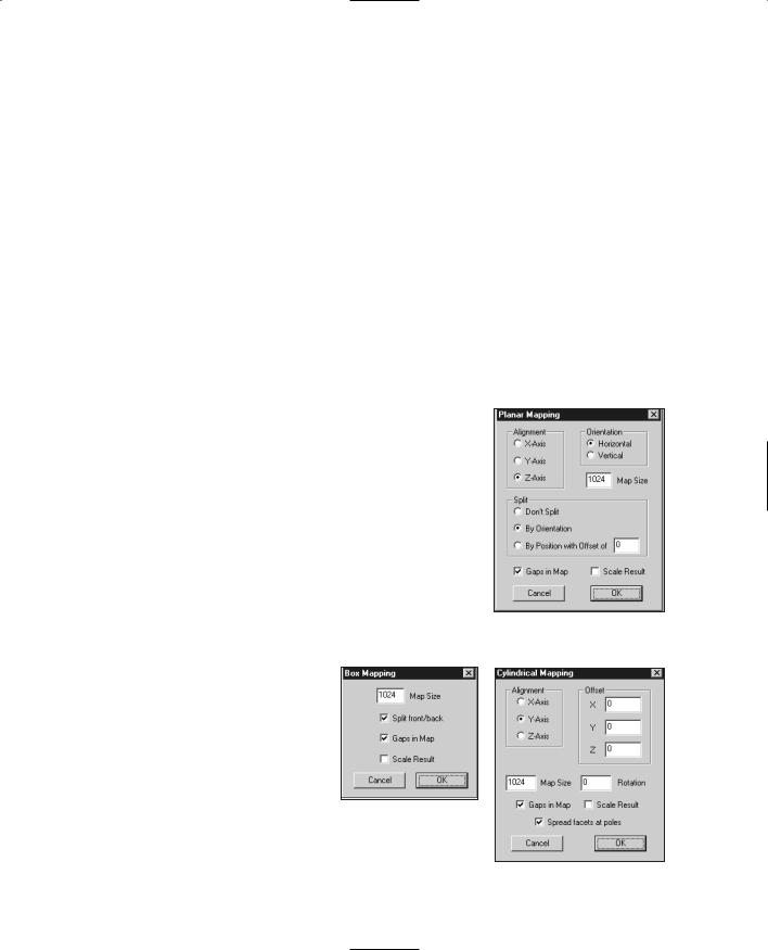
When you use the Planar method, you will be presented with the dialog box depicted in Figure 13.24. Table 13.21 provides details about using the Planar method.
Box
When you use the Box method, you will be presented with the dialog box depicted in Figure 13.25. You can get more information on using the Box method in Table 13.22.
Cylindrical
When you use the Cylindrical method, you will be presented with the dialog box depicted in Figure 13.26. Table 13.23 provides details about using the Cylindrical method.
Figure 13.24 The Planar Mapping dialog box.
Figure 13.25 The Box
Mapping dialog box.
Figure 13.26 The Cylindrical
Mapping dialog box.
Team LRN
410 Chapter 13 ■ Introduction to Modeling with MilkShape
|
Table 13.20 |
UVMapper Hot Keys |
|
|
Key |
Description |
|
|
Esc |
clears selection, undoes changes |
|
|
Enter |
clears selection, saves changes |
|
|
Shift+number key |
increases resize/movement amount |
|
|
keypad * |
quadruples size of selection |
|
|
keypad / |
quarters size of selection |
|
|
keypad + |
increases size of selection |
|
|
keypad - |
decreases size of selection |
|
|
keypad # |
moves selection |
|
= |
maximizes selection |
||
. |
snaps selection to facets |
||
[ |
hides selected facets |
||
] |
shows selected facets |
||
\ |
toggles facets on and off |
||
' |
hides unselected facets |
||
|
uU/vV |
resizes selection (fine) |
|
|
x/X/y/Y |
resizes selection (coarse) |
|
|
Ctrl+x |
inverts selection horizontally |
|
|
Ctrl+y |
inverts selection vertically |
|
|
Ctrl+b |
loads background |
|
|
Ctrl+c |
clears background |
|
|
Ctrl+u |
flips background horizontally |
|
|
Ctrl+v |
flips background vertically |
|
|
Tab |
toggles background display |
|
|
t |
triangulates object |
|
|
Insert |
checks for degenerate facets |
|
|
|
|
|
Cylindrical Cap
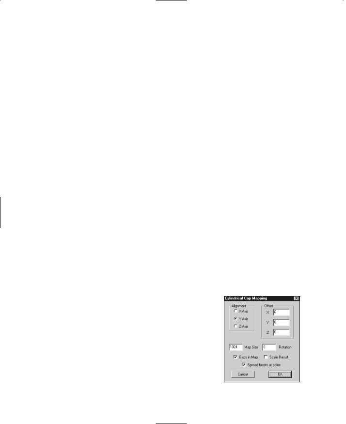
When you use the Cylindrical Cap method, you will be presented with the dialog box depicted in Figure 13.27. Table 13.24 provides details about using the Cylindrical Cap method. This method is similar to the Cylindrical method, except that it assumes you are unwrapping a cylinder with end caps, as if there were closed lids on both ends of a can. The caps are mapped separately from the tubing of the cylinder.
Figure 13.27 The Cylindrical
Cap Mapping dialog box.
Team LRN

UVMapper |
411 |
|
Table 13.21 |
Planar Mapping Options |
|
|
Option |
Description |
|
|
Alignment |
This allows you to specify the axis along which the model will be mapped. |
|
|
Orientation |
This allows you to alter the layout of the texture map template. It only has an |
|
|
|
effect when using the Split option (described later in this table). If you select Don't |
|
|
|
Split, the Orientation option has no effect. When splitting the model into front and |
|
|
|
back sections, you can have the two halves side by side (Horizontal) or above and |
|
|
|
below each other (Vertical). Which you want to use really depends on the |
|
|
|
geometry of the model. If you don't like the layout of the texture map after using |
|
|
|
planar mapping, try changing this option. |
|
|
Map Size |
This will specify the maximum dimension of the texture map template. Depending |
|
|
|
on the model it may be vertical or horizontal, but the texture map is guaranteed |
|
|
|
not to exceed this value in either width or height. One side will equal this value, |
|
|
|
and the other will be scaled accordingly. |
|
|
Split |
This option allows you to divide the texture map into front and back sections. (To |
|
|
|
adjust the placement of these sections, see the Orientation option earlier in this |
|
|
|
table.) You have three options. Don't Split will give you one map with the front |
|
|
|
and back facets on top of each other. By Orientation will calculate the facet |
|
|
|
normals, placing all facets that face toward the eye on one side, and placing all |
|
|
|
facets that face away on the other. By Position with Offset of allows you to divide |
|
|
|
the model based on geometry rather than facing. Using an offset of 0 will divide |
|
|
|
the model in half. You can adjust this offset to change how many facets are on |
|
|
|
each side. |
|
|
Gaps in Map |
This allows you to separate the sides of the box on the texture map. If the sides |
|
|
|
touch, sometimes you will see one pixel of the side on the front, for example. |
|
|
Scale Result |
Use this option to specify how much larger or smaller the resulting texture map |
|
|
|
should be. |
|
|
|
|
|
|
Table 13.22 |
Box Mapping Options |
|
|
Option |
Description |
|
|
Map Size |
This will specify the maximum dimension of the texture map template. Depending |
|
|
|
on the model it may be vertical or horizontal, but the texture map is guaranteed |
|
|
|
not to exceed this value in either width or height. One side will equal this value, |
|
|
|
and the other will be scaled accordingly. |
|
|
Split front/back |
Setting this option will divide the model into six sections: front, back, top, bottom, |
|
|
|
left side, and right side. Uncheck this option if you want to combine top and |
|
|
|
bottom, left and right, front and back, giving you only three sections. |
|
|
Gaps in Map |
This allows you to separate the sides of the box on the texture map. If the sides |
|
|
|
touch, sometimes you will see one pixel of the side on the front, for example. |
|
|
Scale Result |
Use this option to specify how much larger or smaller the resulting texture map |
|
|
|
should be. |
|
|
|
|
|
Team LRN

412 Chapter 13 ■ Introduction to Modeling with MilkShape
|
Table 13.23 |
Cylindrical Mapping Options |
|
|
Option |
Description |
|
|
Map Size |
This will specify the maximum dimension of the texture map template. Depending |
|
|
|
on the model it may be vertical or horizontal, but the texture map is guaranteed |
|
|
|
not to exceed this value in either width or height. One side will equal this value, |
|
|
|
and the other will be scaled accordingly. |
|
|
Split front/back |
Setting this option will divide the model into six sections: front, back, top, bottom, |
|
|
|
left side, and right side. Uncheck this option if you want to combine top and |
|
|
|
bottom, left and right, front and back, giving you only three sections. |
|
|
Gaps in Map |
This allows you to separate the sides of the box on the texture map. If the sides |
|
|
|
touch, sometimes you will see one pixel of the side on the front, for example. |
|
|
Scale Result |
Use this option to specify how much larger or smaller the resulting texture map |
|
|
|
should be. |
|
|
|
|
|
Table 13.24 Cylindrical Cap Mapping Options
Option |
Description |
Alignment |
This allows you to specify the axis around which the model will be |
|
mapped. |
Offset |
When mapping a model with one of these methods (Cylindrical, Cylindrical |
|
Cap, or Spherical) the model is mapped around a center point. This center |
|
is calculated using the maximum and minimum geometry values along |
|
each axis. This works quite well for mapping a true sphere or cylinder, but if |
|
you have a model that is, say, a sphere with a spike on the side of it, the |
|
calculated center may not be what you want. To adjust the center of the |
|
model from what's been calculated, use this option. |
Map Size |
This will specify the maximum dimension of the texture map template. |
|
Depending on the model it may be vertical or horizontal, but the texture |
|
map is guaranteed not to exceed this value in either width or height. One |
|
side will equal this value, and the other will be scaled accordingly. |
Rotation |
Use this to specify how much, if any, rotation will be applied to the |
|
resulting texture map image template. |
Gaps in Map |
This allows you to separate the sides of the box on the texture map. If the |
|
sides touch, sometimes you will see one pixel of the side on the front, for |
|
example. |
Scale Result |
Use this option to specify how much larger or smaller the resulting texture |
|
map should be. |
Spread facets at poles |
Oftentimes facets are squeezed together when the mapping occurs, |
|
especially at places like the "poles" (the tops and bottoms of the map, just |
|
like on maps of the Earth). With this option set, the resulting map will |
|
spread the facets at the poles to alleviate the pinching effect. |
Team LRN
UVMapper 413
Spherical
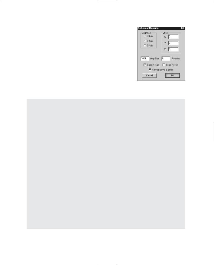
When you use the Spherical method, you will be presented with the dialog box depicted in Figure 13.28. You can get more information on using the Spherical method in Table 13.25.
|
Figure 13.28 The Spherical |
|
|
Mapping dialog box. |
|
Table 13.25 |
Spherical Mapping Options |
|
Option |
Description |
|
Alignment |
This allows you to specify the axis around which the model will be mapped. |
|
Offset |
When mapping a model with one of these modes (Cylindrical, Cylindrical Cap, |
|
|
or Spherical) the model is mapped around a center point. This center is |
|
|
calculated using the maximum and minimum geometry values along each axis. |
|
|
This works quite well for mapping a true sphere or cylinder, but if you have a |
|
|
model that is, say, a sphere with a spike on the side of it, the calculated center |
|
|
may not be what you want. To adjust the center of the model from what's been |
|
|
calculated, use this option. |
|
Map Size |
This will specify the maximum dimension of the texture map template. |
|
|
Depending on the model it may be vertical or horizontal, but the texture map is |
|
|
guaranteed not to exceed this value in either width or height. One side will |
|
|
equal this value, and the other will be scaled accordingly. |
|
Rotation |
Use this to specify how much, if any, rotation will be applied to the resulting |
|
|
texture map image template. |
|
Gaps in Map |
This allows you to separate the sides of the box on the texture map. If the |
|
|
sides touch, sometimes you will see one pixel of the side on the front, for |
|
|
example. |
|
Scale Result |
Use this option to specify how much larger or smaller the resulting texture map |
|
|
should be. |
|
Spread facets at poles Oftentimes facets are squeezed together when the mapping occurs, especially at places like the "poles" (the tops and bottoms of the map, just like on maps of the Earth). With this option set, the resulting map will spread the facets at the poles to alleviate the pinching effect.
Team LRN

414 Chapter 13 ■ Introduction to Modeling with MilkShape
Moving Right Along
Well, there you have two pretty comprehensive, low-cost modeling tools: MilkShape 3D by Mete Ciragan and UVMapper by Steve Cox. These guys have done an admirable job creating these programs in the shareware or freeware spirit. They deserve not only a round of applause and big thank you, but you could also perhaps send a few dollars their way by registering their shareware programs. The cost is minuscule, and the benefits are great.
By using the common Wavefront file format, we can use each tool in complementary ways to create models for our games. This is a pretty common theme; notice also that we've used Paint Shop Pro—another low-cost tool—in the same way in conjunction with MilkShape. In the next few chapters we will tackle the Big Jobs: animated characters, vehicles, and weapons. It would not be wasted effort if you wanted to take some time out at this point to practice by designing and building some models to your own specifications.
The more you use a tool, make mistakes, and figure out what you did wrong and then make any necessary corrections on your own, the more proficient you will become.
Team LRN
chapter 14
Making a
Character Model
n this chapter we are going to build a character model, step by step. We are going to |
|
|
animate it and skin it. It's going to be a long and sometimes hectic ride, so hang on |
|
|
Ito your hat! |
|
|
Modeling Techniques |
|
|
There are many different approaches or techniques that modelers use. The differences can |
|
|
be based on what tools are available to do a given job or what data is available about the |
|
|
item to be modeled. There are other techniques available not described here—that's |
|
|
because we are modeling for games, and low-poly modeling is the philosophy we need to |
|
|
follow. Remember that the more polygons one model uses, the fewer polygons available |
|
|
for other instances of that model, or for other models, in a given rendered frame of a scene |
|
|
at a given frame rate. In games there is that polygon budget to consider. |
|
|
Shape Primitives |
|
|
Creating models using shape primitives can be an extremely quick way to build a low-poly |
|
|
model, depending on your expertise and eye for detail. The basic technique involves |
|
|
selecting a primitive that best matches the part of the model you are building. The prim- |
|
|
itive shape must contain enough polygons and vertices for you to adjust the shape to |
|
|
closely match your target. |
|
|
This is the technique we are going to use to build our character model in this chapter. |
|
|
Incremental Polygon Construction |
|
|
Incremental Polygon Construction is a method that fairly closely approximates modeling |
415 |
|
with clay in the real world. Sculpting with clay generally involves adding bits of clay |
||
|
Team LRN

416Chapter 14 ■ Making a Character Model
together to create shapes that grow in size and detail. The clay can be poked and prodded, smoothed and pinched until it accurately depicts the item being modeled.
With Incremental Polygon Construction, the process is similar: We apply vertices in 3D space that represent high points and low points of the features to be modeled, and then we build triangles or faces connecting these vertices. One point of departure from clay modeling is that we typically don't add faces on top of (such that they completely obscure) other faces, because we have no need for a solid to give us the required volume. But the principle of adding faces to the existing topology of a model as the model grows is the same, as is the useful concept that we add only what we need, and no more.
The best way to get started with modeling in this way is to use photographs or sketches of the target from several directions: from directly in front, directly above, and one or both sides. From the pictures we can obtain the locations and shapes of the features and their high and low points. We mark these points in our 3D views, and then we proceed to build faces from them.
This technique can be quite slow going. It is also prone to errors that are difficult to correct, because you may have moved dozens of steps beyond where the real error occurred before the error becomes evident.
Axial Extrusion
In the simplest sense, you start with a primitive object (usually a box, but it could be a simple facet or triangle), subdivide it, and then select specific polygons to extrude into meshes to form general shapes. When you subdivide objects, you increase the number of polygons on each side of the shape. You then adjust and refine the extruded polygons to form the details of the model. This approach is similar to making models of geographic terrain using a contour map as a guide, with cardboard or plywood sheets to build up the terrain, and then smoothing the edges with some kind of filler.
With Axial Extrusion, you limit your extrusions to one of the three axes— sometimes all three in various combinations—but individual extrusion only occurs in one axis. This technique is usually restricted to inanimate objects, but sometimes certain parts of character models are made this way.
One example of using axial intrusion in character modeling is when creating a head. A series of flat-plane profiles (called cuts) are made of a head, after which each profile is extruded once in each direction on the transverse axis (the axis that runs from ear to ear). Then each extruded mesh is married to the extruded meshes of the adjacent cuts by an averaging of the vertices. You'll actually get to do some of these extrusions later in this chapter, and others.
Team LRN

The Base Hero Model |
417 |
Arbitrary Extrusion
Arbitrary Extrusion has much in common with Axial Extrusion, except that you extrude your base primitive shapes in whatever directions are necessary. Like Incremental Polygon Construction, this approach to modeling can be seen as similar to sculpting in clay. Machinery lends itself well to modeling with this technique.
Topographical Shape Mapping
Topographical Shape Mapping is a method usually used to model terrain, like Axial Extrusion often is, except that Topographical Shape Mapping is best suited for automated operations rather than manually modeling.
In the geographic sense, topographic data can be obtained from various government and private sources. The data consists of, at a minimum, a coordinate and an altitude for each mapped point on the real terrain's surface. There are various algorithms and many programs available that can read this data from a file and render a 3D view of the terrain in question. The data files come in various formats depending on the agency that produces them: DLG-O, DEM, SDTS, and DRG, to name just a few from that acronymic world. Normally this approach is used in one of the many available Geographic Information Systems (GIS), and there are tools that can convert this data into a format you can use for modeling in games.
Hybrids
Well, the Hybrid category is the catchall category. Often it is prudent to combine techniques in a single model—use the approach that works best for the component being created. If you find yourself mixing techniques, most likely you will be doing a little bit of Incremental Polygon Construction mixed with many shape primitives or using a few primitives mixed with a great deal of Arbitrary Extrusion.
The best point to be made here is that you should use what works best for you in your current circumstances.
The Base Hero Model
The technique we are going to use is basically the Shape Primitives approach. We will hand-modify various shape primitives to get the results we want.
The kind of model we are going to make is primarily a segmented-mesh model. An alternative would be a continuous-mesh model. The difference is that in the segmented-mesh model, there are different, distinct objects or meshes for different components in the model, whereas in the continuous-mesh model, the entire model has one large, convoluted surface. Our primary segments will be as follows:
Team LRN