

3D Game Programming All In One (2004)
.pdf398 Chapter 13 ■ Introduction to Modeling with MilkShape
The Toolbox
Way back near the start of this chapter, in Figure 13.2, is a depiction of the contents of the various tabs in the toolbox. In this section here we will dig deeper into the capabilities in those tabs. Table 13.10 provides a brief summary of each toolbox tab's functions.
Table 13.10 MilkShape Toolbox Summary
Tab |
Purpose |
Model |
This is used for the placement of vertices and shape primitives, as well as for the |
|
construction of polygons and skeletons. |
Groups |
This contains commands used to group vertices and polygons. Groups can also be |
|
created from existing polygons. |
Materials |
This deals with the creation of materials, including textures from file, ready to be |
|
assigned to groups. |
Joints |
This contains tools for manipulating and managing skeleton joints. |
You should understand that, in general, when using the functions in the toolbox, we will first have to select some object via one of the views and then operate on it using one of the toolbox commands. This sort of noun-verb operation mode requires us to make sure we have the appropriate objects selected before every action we take.
The Model Tab
The Model tab (see Figure 13.18) contains the tools necessary to create and modify the basic shape primitives: vertices, faces, cylinders, spheres, and cubes (boxes, as MilkShape calls them). Table 13.11 shows the functions of the Model tab's buttons.
Figure 13.18 The
Model tab.
Team LRN

MilkShape 3D |
399 |
Table 13.11 Model Tab Functionality
Button |
Description |
Select |
This tool puts the program into select mode so that the user can select any object |
|
or collection of objects on one of the wire-frame views. Once you are in select |
|
mode, you can specify one of four different selection target types: vertex, face, |
|
group, or joint. You also have two optional settings: ignore backfaces and by |
|
vertex (which is only available in face selection mode). |
Move |
This tool permits you to move any selected objects by clicking in the appropriate |
|
wire-frame view and dragging the cursor. You can also specify discrete movement |
|
by entering numbers in the Move Options boxes at the bottom. |
Rotate |
This tool permits you to move and rotate any selected objects around a single axis |
|
by clicking in the appropriate wire-frame view and dragging the cursor up or |
|
down. You can also specify discrete rotations and multiple axes rotations by |
|
entering numbers in the Rotate Options boxes at the bottom. |
Scale |
With this tool you can change the size of any selected objects along one of two |
|
available axes in each view by clicking in the appropriate wire-frame view and |
|
dragging the cursor up, down, left, or right. You can also specify discrete scaling and |
|
multiple axes scaling by entering numbers in the Scale Options boxes at the bottom. |
Vertex |
Use this tool to place individual vertices, one at a time, in a wire-frame view. In |
|
each different view, the vertex will be placed at the zero axis position for |
|
whichever axis is not presented in the view. This tool has no options. |
Face |
With this tool you can connect individual vertices to create a face, one vertex at a |
|
time, with three vertices defining a face. The Threshold option specifies how close |
|
to a vertex you need to click to add it to the current face you are building. As you |
|
build the face, select the vertices in a counterclockwise direction to create an |
|
outward normalized face. |
Sphere |
This tool is a shape primitive tool. To create a sphere, simply click and drag the |
|
cursor in a wire-frame view. With the Sphere options you can specify the number |
|
of slices (like the slices in a pie) or stacks (like a stack of pancakes) that make up |
|
your sphere. |
GeoSphere |
Use this tool to create more realistic spheres using a different program technique. |
|
You use the tool the same way as the Sphere tool, but you can only specify the |
|
complexity of the sphere using the Depth option. |
Box |
Use this tool to create cubes. Just click in a wire-frame view and drag until it has |
|
reached the size you want. |
Cylinder |
Use this tool the same way as you use the Sphere tool, even including the |
|
specification of stacks and slices. |
Extrude |
This tool operates only on the faces. If you have two faces aligned to create a |
|
flat surface, like a piece of cardboard, you would use this tool to extend the |
|
surface in a specific direction to create a box. Just click the mouse and drag to |
|
perform the extrusion. Using the Extrude options you can specify which directions |
|
to do the extruding in—normally you would use only one direction at a time. The |
|
Smoothing option tells the program to smooth shade the polygons as it draws the |
|
extruded shape. |
|
continued |
Team LRN
400 |
Chapter 13 |
■ Introduction to Modeling with MilkShape |
||
|
|
|
|
|
|
Joint |
|
This tool places special joint objects. It works the same as the Vertex tool, |
|
|
|
|
except that if an existing joint is already selected when you make the new |
|
|
|
|
joint, the new joint will be attached to the previous one by a bone. If the |
|
|
|
|
Show Skeleton option is turned on in the Joint tab, the bone will be visible |
|
|
|
|
in yellow. |
|
|
Redraw All Viewports |
If you have this option turned on, then every time you perform one of the |
||
|
|
|
tool operations, the views in all the viewports will be redrawn to reflect |
|
|
|
|
your changes. |
|
|
Auto Tool |
|
If you have this option turned on, then the program will alternate between |
|
|
|
|
any tool and the Select tool each time you finish an operation. This option is |
|
|
|
|
handy for tweaking and repetitive adjustment techniques. |
|
|
|
|
|
|
|
|
|
The Groups Tab |
|
|
|
|
||
|
|
|
You will often want, or need, to organize your model faces into |
|
|
|
|
groupings that make either visual or logical sense. Whether you |
|
|
|
|
organize them as meshes that make visual sense or simply as logi- |
|
|
|
|
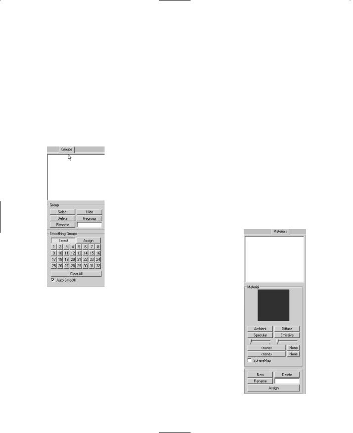
cal groups, you do this with the Groups tab, shown in Figure 13.19. |
|
|
|
|
The Torque DTS Exporter uses special groups with the name colli- |
|
|
|
|
sion to define collision meshes. Table 13.12 presents the functions |
|
|
|
|
available from the Groups tab. |
|
|
|
|
The Materials Tab |
|
|
|
|
|
|
|
|
|
With the Materials tab (see Figure 13.20), |
|
|
|
|
you can define the textures that will be |
|
|
|
|
used to skin your model, as well as what |
|
|
|
|
characteristics they will have when dis- |
|
|
|
|
played. Special materials are also used to |
|
|
|
|
define certain model characteristics to the |
|
|
Figure 13.19 |
The |
||
|
Torque DTS Exporter. Table 13.13 explains |
|
||
|
Groups tab. |
|
|
|
|
|
the functions of the Materials tab. |
|
|
|
|
|
|
|
|
|
|
|
|
Figure 13.20 The
Materials tab.
Team LRN

MilkShape 3D |
401 |
Table 13.12 Groups Tab Functionality
Button |
Description |
Group Selector Box |
This is the white area at the top. It contains the names of the |
|
groups, one group per line. You always need to choose a group from |
|
this box before performing any group operations. |
Select |
When you use this tool, the currently chosen group in the list will |
|
become selected in the wire-frame views—that is, it will become |
|
drawn in red. Each time you choose a different group and click the |
|
Select tool, that group gets added to each view's selection. |
Hide |
With this tool you can make the chosen group's faces and vertices |
|
become invisible. This is useful for uncluttering a view or to ensure |
|
that you don't select the wrong parts for another operation. |
Delete |
Use this tool to permanently remove a group from the model. |
Regroup |
With this tool you create new groupings from whatever model |
|
elements are selected (shown in red) in the views. Any elements that |
|
already belong to other groups are removed from those groups and |
|
added to the new group. |
Rename |
Choose a group, type a new name in the Rename box, and then click |
|
the Rename tool. Bingo! The group now has a new name. |
Smoothing Groups Select |
Pressing this key and then one of the Smoothing Group numbers |
|
selects the polygons assigned to that Smoothing Group. Smoothing |
|
Groups can only be selected on the numbers that have been |
|
assigned. |
Smoothing Groups Assign |
When you have a group of polygons selected you can press this |
|
button and then one of the Smoothing Group numbers to assign all |
|
selected polygons to a Smoothing Group. Additional groups of |
|
polygons can be added to the same group without overwriting the |
|
previous contents of the Smoothing Group. |
Smoothing Group Numbers |
These numbers act as a storage bank for groups of polygons. They |
|
can have polygons assigned to them and selected from. If the Auto |
|
Smooth check box is selected, assigning groups of polygons to a |
|
Smoothing Group number will smooth shade them (Smooth Shaded |
|
shading has to be enabled to view the effect of this—right-click the |
|
3D Perspective view and click Smooth Shaded from the pop-up |
|
menu). |
Smoothing Group Clear All |
This button removes the assigned Smoothing Groups from the |
|
Smoothing Group numbers. The polygons will remain smooth |
|
shaded, but they will no longer be in the same Smoothing Group. |
Smoothing Group Auto Smooth |
When assigning Smoothing Groups, ensure this is checked if you |
wish |
the selected polygons to be smooth shaded. |
Team LRN

402 Chapter 13 ■ Introduction to Modeling with MilkShape
Table 13.13 Materials Tab Functionality
Item |
Description |
Material Selector Box |
This is the white area at the top. It contains the names of the |
|
materials, one material per line. You always need to choose a material |
|
from this box before performing any material operations. |
Material Preview |
The currently chosen material is displayed, mapped onto a sphere. You |
|
can click and drag the sphere with the mouse to view hidden parts of |
|
the material map. |
Ambient |
Use this tool to get a color picker window for setting the ambient light |
|
of the environment the material is in. This attribute affects the color |
|
and the intensity of the color that the material reflects. |
Diffuse |
Use this tool to get a color picker window for setting the light that the |
|
material will directly reflect. This attribute has the most influence over |
|
the color of the material. |
Specular & Specular Slider |
Use this tool to set the specular highlight of the material. Basically, |
|
selecting a bright color will create a highlight on the material of the |
|
color chosen. Moving the slider below it changes the focus of the |
|
highlight. The highlight can range from appearing as a small spot to |
|
appearing as if the object is immersed in incandescent light. |
Emissive |
Use this tool to get a color picker window for setting the color and |
|
intensity of the light that the material emits. This attribute will appear |
|
as a glow around the material. |
Transparency Slider |
This slider adjusts the amount of transparency that an alphamap |
|
applies to a texture and the faces that the texture is assigned to. You |
|
must click Assign or click in the viewport to update the model to |
|
reflect your changes. |
Texture Browse Button |
Use this tool to select a texture to apply to the material. Pressing it |
|
will reveal a Windows Explorer browse box from which image files can |
|
be selected. The None button beside this button removes the texture |
|
file from the material. |
Alphamap Browse Button |
Use this tool to apply an alphamap to the material. A black-and-white |
|
image can be used to remove areas of texture where there may be |
|
holes. Black is fully occluded and white is fully visible; it is possible to |
|
use variations of gray to achieve semitransparency. The None button |
|
beside this button removes the alphamap file from the material. |
New |
The New button, when pressed, will create a new blank material with |
|
default attributes, no texture or alphamap files, and a default name. |
Delete |
To delete a material, choose it in the Material Selector, and then click |
|
the Delete button. This literally removes the material from the |
|
workspace, so use this wisely. |
Rename Button & Box |
To rename a material, choose it in the Material Selector box, type the |
|
desired name in the box next to the Rename button, and then click the |
|
Rename button. |
Assign |
Use this tool to assign the chosen material in the Material Selector box |
|
to the selected group. |
Team LRN
|
MilkShape 3D |
403 |
The Joints Tab |
|
|
|
|
|
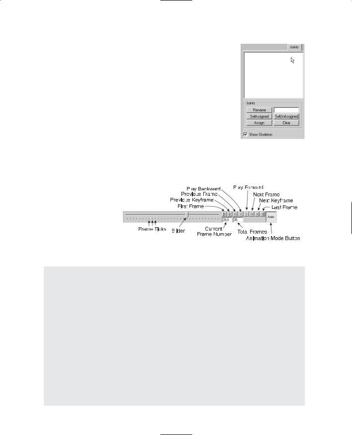
Using the Joints tab (see Figure 13.21), you can specify the joints for |
|
|
skeletons, which are used in animations. Joints are also used as sub- |
|
|
stitutes for the concepts of special nodes that are used by the Torque |
|
|
DTS Exporter. Table 13.14 describes the Joints tab functions. |
|
|
The Keyframer |
|
|
The Keyframer (see Figure 13.22) is a special tool used for defin- |
|
|
ing animations for your model. With it, you can save skeletal posi- |
|
|
tions in a model. You then produce animation by storing several |
|
|
keyframes to the Keyframer and playing them back. There is a set |
Figure 13.21 The |
|
of controls for managing the playback. Typically, only frames |
Joints tab. |
|
where changes take place need to be set by the user; hence the |
|
|
term keyframe—they are key to the animation. MilkShape 3D will fill in the pose or posi-
tion |
frames between |
|
|
|
|
|
|||
|
|
|
|
|
|||||
the |
keyframes. |
You |
|
|
|
|
|
||
|
|
|
|
|
|||||
must |
click |
the |
Anim |
|
|
|
|
|
|
button at |
the |
lower |
|
|
|
|
|
||
right in order to work |
|
|
|
|
|
||||
with the Keyframer. |
|
|
|
|
|
||||
Table |
13.15 |
describes |
|
|
|
|
|
||
|
|
|
|
|
|||||
the primary Keyframer |
|
|
|
|
|
||||
Figure 13.22 The Keyframer. |
|||||||||
functions. |
|
|
|||||||
|
|
|
|
|
|
|
|||
Table 13.14 Joints Tab Functionality
Item |
Description |
Joint Selector Box |
This is the white area at the top. It contains the names of the joints, one joint |
|
per line. You always need to choose a joint from this box before performing |
|
any operations on joints. |
Rename Button & Box These tools work the same as the Rename tools in the other tabs: Choose a joint, type a new name in the box, and then click the Rename button.
SelAssigned |
After you have chosen a joint, press this button to select all the vertices |
|
assigned to that particular joint. |
SelUnAssigned |
Press this button to select all vertices not assigned to the chosen joint. |
Assign |
Use this tool to assign vertices to a joint. To do this, choose the Select-Vertices |
|
tool from the Model tab, highlight the joint in the Joint Selector box that you |
|
wish to assign the vertices to, and then select the vertices and click Assign. |
Clear |
Press this button to clear all the assigned vertices from belonging to the |
|
chosen joint in the Joint Selector box. |
Team LRN
404 Chapter 13 ■ Introduction to Modeling with MilkShape
Table 13.15 Keyframer Functionality
Component |
Description |
Keyframe Slider |
Use the slider to preview your animation before playing it. Using the |
|
slider, you can move freely backward and forward between the |
|
frames with mouse movement instead of pressing the Play Forward |
|
and Play Backward buttons to see the animation. It is useful for |
|
selecting animation frames in smaller animations; use the Frame |
|
Position box to select frames for larger animations with many (more |
|
than a dozen or so) frames. |
Playback Controls |
The playback controls allow you to view your animation in MilkShape |
|
3D in a manner similar to a VCR or DVD player. From the left, the |
|
buttons are First Frame, Previous Keyframe, Previous Frame, Play |
|
Backward, Play Forward, Next Frame, Next Keyframe, and Last Frame. |
|
All of these commands update the model to the current frame, and |
|
the slider is also moved to the appropriate frame. |
Current Frame Number Box |
Use this box when you have a lot of frames in your animation and |
|
the slider does not allow the accuracy you desire when selecting |
|
frames. You can type in a value here that will set the number of |
|
frames in the animation. The box will accept a whole number to |
|
indicate the frame to which you wish to go; the slider and view will |
|
change to reflect the selected frame. |
Total Frames Box |
In this box, enter the number of frames you want in your animation. |
|
Most modelers choose a relatively high number, depending on the |
|
number of animations the model is to perform, and key in animations |
|
between certain numbers of frames leaving a threeor four-frame |
|
gap between animations. With a Run, Walk, Jump, and Shoot |
|
animation, you would key in the Run animation first and then leave |
|
several frames, key in the Walk animation and then leave several |
|
frames, and so on. |
Animate Button |
This button enables the Keyframer. It behaves like a toggle—when |
|
down, the Keyframer is enabled; when up, the Keyframer is disabled. |
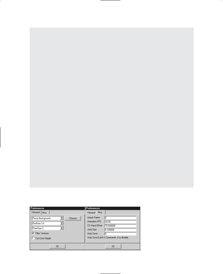
The Preferences Dialog Box
The Preferences dialog box (see Figure 13.23), which you reach by choosing File, Preferences, has two tabs. The Viewport tab is used to set up the viewports' attributes, and the Misc tab offers miscellaneous settings. Table 13.16 provides details about each setting in the two tabs.
Figure 13.23 The Preferences dialog box.
Team LRN

MilkShape 3D |
405 |
|
Table 13.16 |
Preference Choices |
|
|
Component |
Description |
|
|
Property Selector |
With MilkShape, the user can customize the colors of components used |
|
|
|
when modeling. The drop-down list contains the component names; a |
|
|
|
color for the selected component can then be chosen by clicking the |
|
|
|
Choose button next to the drop-down box. Following is the complete list |
|
|
|
of color customizable components: |
|
|
|
perspective background (the 3D view) |
|
|
|
orthographic background (the 2D views) |
|
|
|
perspective grid |
|
|
|
orthographic grid |
|
|
|
X-Axis |
|
|
|
Y-Axis |
|
|
|
Z-Axis |
|
|
|
vertex |
|
|
|
selected vertex |
|
|
|
face |
|
|
|
selected face |
|
|
|
bone |
|
|
|
selected bone |
|
|
|
selected joint |
|
|
|
keyed bone |
|
|
Grid Size |
Use this control to set the spacing of the grid lines in the wire-frame |
|
|
|
views. The default grid size is 1 1; this gives the smallest line spacing. |
|
|
|
The grid size you use usually depends on the scale of the models you are |
|
|
|
building. |
|
|
Point Size |
Use this control to specify the size of the vertex points displayed in the |
|
|
|
wire-frame views. Larger point sizes are easier to see and to select |
|
|
|
individually, but they may tend to obscure model details in crowded areas |
|
|
|
at low view magnifications. |
|
|
Filter Textures |
When set, this turns on mipmapping texture filters. This will smooth the |
|
|
|
texture so that the rasterized pixels are not as noticeable. |
|
|
Can Line Stipple |
When moving, scaling, or extruding objects, MilkShape draws a guideline |
|
|
|
that indicates the vector of the action, denoting its direction and |
|
|
|
magnitude. This is usually a solid line, but with this option set, it is |
|
|
|
rendered as a dashed or dotted line. This also stipples the box line used |
|
|
|
for multiple selections. |
|
|
Import Frame |
This allows the user to specify the animation frame to be imported from |
|
|
|
MD2 or MD3 files using the Morph Target Animation mechanism. |
|
|
Animation FPS |
This specifies the playback speed of animations in Frames Per Second (FPS). |
|
|
CS Hand Offset |
This is used to specify the offset for either side of a decompiled |
|
|
|
CounterStrike model. |
|
|
|
continued |
|
|
|
|
|
Team LRN

406 |
Chapter 13 ■ |
Introduction to Modeling with MilkShape |
|
|
|
|
Joint Size |
This allows the user to set the display size of the joints that are used in |
|
|
MilkShape. You should change the size to reflect the scale of the model |
|
|
you work with. |
|
Auto Save |
This option allows you to specify how often the program will |
|
|
automatically save your work. The frequency is defined by how many |
|
|
commands or operations you want to be able to perform before the save |
|
|
happens. This option can be a lifesaver but can also be a nuisance if you |
|
|
set the value too low—especially if you are doing a lot of experimenting |
|
|
and undo your previous operations frequently. A setting of about 10 seems |
|
|
to work well. |
|
|
|
Other Features
MilkShape has a few other features that we won't cover in great depth, but two that deserve at least an honorable mention are the Texture Coordinate Editor and the Message Panel.
The Texture Coordinate Editor provides primitive texture-mapping capability. It has some rather severe limitations that prevent it from being used in even moderately complex models. The biggest limitation is that it doesn't unwrap meshes independently. For this reason we use external tools, like UVMapper. UVMapper may be a bit more awkward to use, because it isn't integrated, but it does a better job, providing more flexibility and control.
The Message Panel displays output from executing plug-ins and modeling operations. It can be useful for providing insight into how MilkShape does its work, but its downfall is the screen space it takes up.
UVMapper
Earlier in this chapter, and even earlier than that in Chapter 9, we used the UVMapper program created by Steve Cox to help us skin a model. As promised, here is the section with the detailed information on UVMapper. We won't cover every detail. Instead, we will concentrate on those details that we can apply to our own needs here in this book.
The first thing to know about UVMapper is that it only operates on models saved in OBJ format, as created by the Alias Wavefront program. The UV unwrapping principles involved are the same for all similar tools. The author of UVMapper has also created UVMapper Pro, a newer release with many more features and greater flexibility. The companion CD includes a demo of UVMapper Pro, a restricted version (you can't save output, which, of course, we need to do). If you want to check out the enhanced features later, go ahead and poke around.
Team LRN

UVMapper 407
The File Menu
As is true in most programs, UVMapper's File menu provides commands for loading, saving, importing, and exporting files. See Table 13.17 for descriptions.
Table 13.17 UVMapper File Menu
Command |
Description |
Load Model |
Load a Wavefront OBJ formatted model from file. After it is loaded, you will |
|
see the texture map layout in the UVMapper window. If you don't, then |
|
there are no texture coordinates included in the model. You can fix this by |
|
choosing Edit, New UV Map (see Table 13.18). |
New Model |
This command gives you a method for adding or creating your own models |
|
from shape primitives. The primitives are box, cone, cylinder, sphere, and torus. |
Import UVs |
With this command you can import UV coordinate data that has been saved |
|
separately from a model. |
Save Model |
Use this command to save the UV mapping data you've created along with |
|
the model you originally imported. |
Save Texture Map |
You can save the texture map image using this command. You can then load |
|
that image as a template into a program like Paint Shop Pro in order to apply |
|
that "artistic magic." |
Export UVs |
With this command you can export only the UV texture coordinates you've |
|
created using this program, without the rest of the model data. |
The Edit Menu
The Edit menu is where the real power of UVMapper resides. Table 13.18 provides more information.
The Help Menu
The Help menu provides the user some assistance when working with the program. Table 13.19 provides more detail, and Table 13.20 provides a list of UVMapper hot keys.
UV Mapping
When you choose Edit, New UV Map you will be presented with a choice of five different unwrapping methods:
■Planar
■Box
■Cylindrical
■Cylindrical Cap
■Spherical
Team LRN