

3D Game Programming All In One (2004)
.pdf378Chapter 12 ■ Terrains
Changing the terrain squareSize in the mission file also affects the control in the Terrain Editor and terrain material painter; you will have more control at smaller sizes. Be sure to change the position values of the terrain to correspond to the worldSize also. For example, if you want more control of the terrain editing, set the squareSize to 4 and the position to 512 512 0:
new TerrainBlock(Terrain) { rotation = "1 0 0 0"; scale = "1 1 1";
detailTexture = "~/data/terrains/details/detail1"; terrainFile = "./myterrain.ter";
squareSize = "4"; locked = "true";
position = "-512 -512 0";
};
Applying Terrain Cover
Terrain textures must be PNG format images and must be 256 by 256 pixels in size. These textures should be placed in a subdirectory under C:\3DGPAi1\fps\data\terrains; they will also work directly in the terrains folder.
Terrain textures are stretched to 2,048 world units (WU) if the terrain squareSize is 8. This means there are 32 repetitions of a terrain texture across one terrain width or depth (1 terrain rep). This also means there are 8 WU per texture pixel (texel).
65,536 WU 32 texture reps=2,048 WU per texture rep 2,048 WU 256 pixels=8 WU per texel
If the terrain squareSize is set to 4 in the mission file, there will still be 32 terrain texture repetitions, but each repetition will only cover 1,024 WU of the terrain.
And although not a requirement, terrain cover textures will look best when they are created to be tiled, as discussed earlier; opposite edges should match so that when they are tiled you won't be able to see the edges. The images in Figure 12.21 and 12.22 are test textures that are 256 by 256 pixels. The checkerboard pattern in Figure 12.21 has each white or black section sized at 128 by 128 pixels.
The grid texture in Figure 12.22 has white lines every 32 pixels and red lines at 128 pixels. You can use these images to calculate the total terrain size
with respect to the dimensions of objects created in
Figure 12.21 Checkerboard texture.
Team LRN
Creating Terrains |
379 |
a map editor as well as to calculate the terrain square size with respect to terrain textures. In addition, you can use the image in Figure 12.22 to create sightlines when manually adjusting terrain heights.
To paint our terrain cover:
1.Place these images in a subdirectory under C:\3DGPAi1\fps\data\terrains.
2.Use the Run fps Demo shortcut to launch Torque.
3.Select the mission you created in the previous section.
4.Press the F8 function key to switch to "fly" mode.
5.Fly up above the terrain a bit using the arrow keys to move and the mouse to aim and look down. You can use F7 to switch out of fly mode when you want.
6.Press F11 to open the World and Terrain Editor.
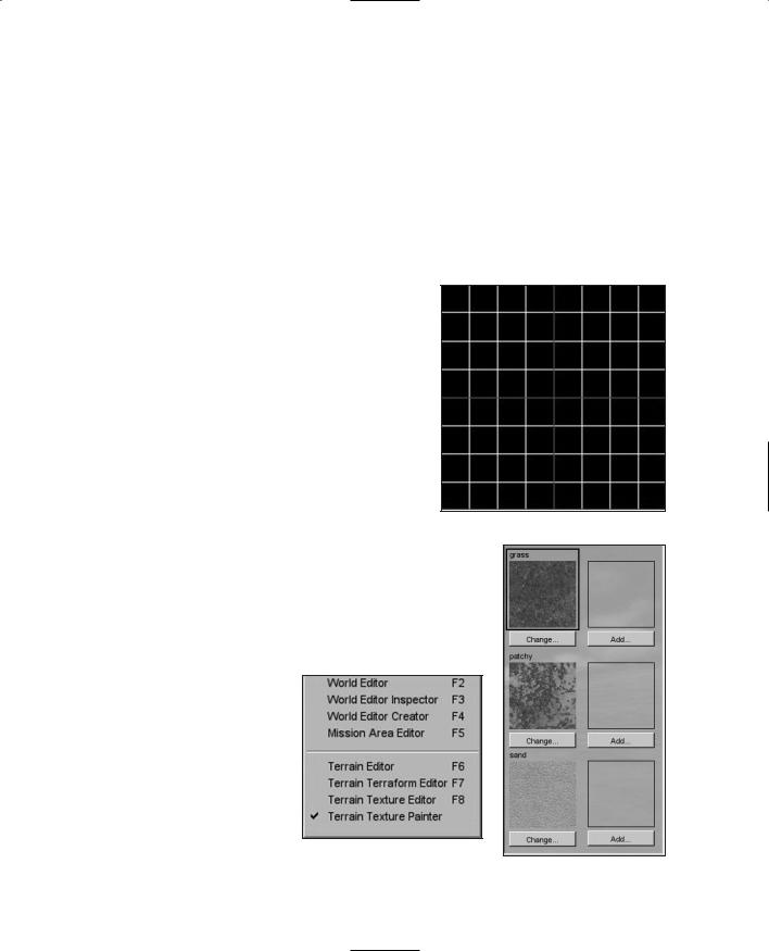
7.Choose Window, Terrain Texture Painter, as shown in Figure 12.23.
You will now see the Material Selection dialog box |
|
(as shown in Figure 12.24) to the right. You can |
|
highlight the material you want to paint with or |
|
change or add new textures here. |
Figure 12.22 Grid texture. |
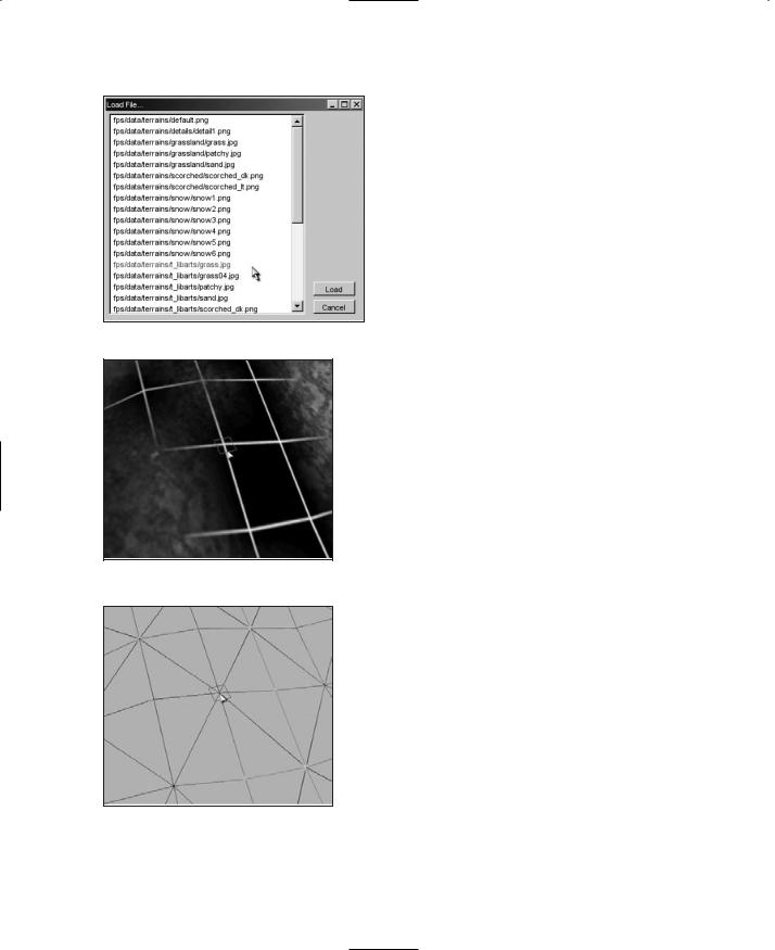
8.To add a new material, click an Add or Change button and you will get a new texture image Load File dialog box, as shown in Figure 12.25.
9.Highlight the image you want and click the Load button. That image is now in your selection set.
10.From the Action pull-down menu, make sure Paint Material is checked.
11.Now go up to the Brush pull-down menu and select your desired brush size.
Remember that we are using the default terrain squareSize set to 8. Table 12.4 lists the area of the terrain that is influenced based on brush size.
Figure 12.23 World Editor Window menu with Terrain Texture Painter checked.
Figure 12.24 Material Selection dialog box.
Team LRN
380 Chapter 12 ■ Terrains
|
Table 12.4 |
Brush Sizes |
|
|
|
|
|
World Units |
|
|
|
|
(texels |
|
|
Brush Size |
Texels |
squareSize) |
|
1 |
1 32=32 |
32 8=256 |
||
3 |
3 32=96 |
96 8=768 |
||
5 |
5 32=160 |
160 8=1,280 |
||
9 |
9 32=288 |
288 8=2,304 |
||
15 |
15 32=480 |
480 8=3,840 |
||
25 |
25 32=800 |
800 8=6,400 |
||
|
|
|
|
|
Figure 12.25 Image Load File dialog box.
Figure 12.26 depicts a texture applied with the brush size set to 1, and Figure 12.27 shows the corresponding terrain grid.
You can see the 32 by 32 texel influence area for one brush that corresponds to 256 WU for the terrain squares shown in the grid view.
So take your trusty Terrain Paint Brush and go nuts!
Moving Right Along
So, now we understand why terrains need to be modeled, and what our options are for obtaining real-world terrain data. If we aren't modeling a real location, we've seen how we can create our own imaginary terrain using Paint Shop Pro, so that we can satisfy the needs of our game. We also looked at terrain cover, and how to create images for use as terrain cover.
We also learned about some of the visual anomalies, like terrain tiling seams that might make our terrains less pleasing, and how we can go about fixing those issues.
Earlier in the chapter, Figure 12.8 showed an example of a finished terrain, with some hills in the distance, and terrain cover applied.
In the next chapter, we'll learn a pair of new tools, MilkShape and UV Mapper.
Team LRN
chapter 13
Introduction to
Modeling with
MilkShape
In this and the following chapters, we will be delving into the world of low-poly modeling. We'll talk about techniques and methods that can be applied to other tools, such as the expensive 3D Max or Maya, but the practical focus will be geared toward using
MilkShape, UVMapper, and other low-cost tools that are included on the enclosed CD.
MilkShape 3D
In Chapter 9 we created a skin for a simple soup can—remember that? Well, in this chapter we're going to create the model and skin it with the texture you created earlier, only this time we will go beyond just the simple soup can. But first, let's start at the beginning and learn a bit about MilkShape.
MilkShape 3D is a great low-cost low-poly 3D modeling tool created by a fellow named Mete Ciragan. Like most successful shareware applications, it has evolved over the years, as Mete added features requested by his user community. He also added the capability for users to create their own plug-ins to provide additional features and import-export filters.
MilkShape is not as complex as the more expensive tools, but that does not in any way imply that it is not a capable program, especially in the low-poly world that computer games inhabit. In fact, the stripped-down nature of MilkShape certainly makes it easier to learn than most of the "big boys."
Installing MilkShape 3D
If you want to install only MilkShape 3D from the enclosed CD, do the following:
1. Browse to your CD in the \MS3D directory. (MS3D is the abbreviated form for
MilkShape 3D. You'll encounter it a fair bit.) |
381 |
|
Team LRN
382 Chapter 13 ■ Introduction to Modeling with MilkShape
2.Locate the Setup.exe file and double-click it to run it.
3.Click the Next button for the Welcome screen.
4.Follow the various screens and take the default options for each one, unless you know you have a specific reason to do otherwise.
n o t e
MilkShape does not know how to open its own files when you double-click them to be launched from Windows Explorer. You need to launch MilkShape first and then browse for your files with the MilkShape File, Open dialog box.
The MilkShape 3D GUI
t i p
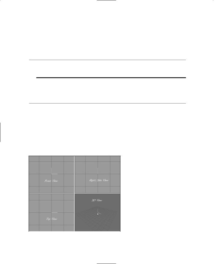
If you only have three views in your window when you first run MilkShape, choose Window, Viewports, 4 Window, and you should get something close to what you see in Figure 13.1.
In Figure 13.1 there are four places where the model can be seen. Each of these is what MilkShape calls a window. We will call them frames in this book, because as you probably already know, MilkShape itself is in a window.
A view is the angle or direction at which you look at an object. For example, if you stand in front of an object and look at it, you are seeing the front view. From above, it is the top view.
A viewport is the little frame inside the MilkShape window in which a view of a model is presented. When I want to direct your attention to a particular viewport, I might refer to it as being in a particular frame. MilkShape calls these frames windows, which is a bit of a misnomer.
|
|
For example, in Figure 13.1 the 3D view is |
|
|
|
in the 3D viewport, located in the lower- |
|
|
|
right frame in the MilkShape window. |
|
|
|
|
|
|
|
You'll notice in Figure 13.1 that |
|
|
|
I've labeled the different views. |
|
|
|
This is the way you should use |
|
|
|
your views for models that you |
|
|
|
create for Torque. Other applica- |
|
|
|
tions and games may require your |
|
Figure 13.1 MilkShape 3D. |
|||
models to be oriented differently. |
|||
Team LRN

MilkShape 3D |
383 |
Three of the views are wire-frame-only views; they allow you to look at your model from directly above, directly in front, and the right-hand side. The fourth view is a 3D view in which you can rotate your model various different ways and view it as a wire-frame, shaded, or fully textured model with lighting cues.
Figure 13.2 shows the tools available in the toolbox section. Although some tools for different operations are only available in the menus, most of the time you will be working with the tools in the toolbox.
Navigating in Views
In the wire-frame views, you can move the view around by holding down the Ctrl key and clicking and dragging in the window.
If you hold down the Shift key and drag the mouse, you can zoom in or out. Be careful though—if you are in select mode (from the Model tab), the program will alternate between zooming and object-selecting each time you press the Shift key and drag the mouse button. With practice you can master this and it will become quite useful. This behavior only occurs in select mode. In all other modes, the shift-drag action will always zoom the view in or out with no alternation.
If you have a wheel mouse, then the wheel can be used to zoom in or out. You will have to click in the view to get focus into the view before the zoom will work.
The 3D view allows the view movement in the same ways as the other views, except the wheel mouse zoom works backward.
View Scale and
Orientation
When you are viewing an object from the front in MilkShape, the Y-axis is positive going up, the X-axis is positive going to the right, and the Z-axis is positive going to the front. This makes it a right-handed coordinate system.
If you look at the Right Side view (the view at the upper right of the four), you will see in the center the axis "bugs" for the Y- and Z-axes. Although it is not
visible in the black-and-white Figure 13.2 The toolbox contents.
Team LRN
384Chapter 13 ■ Introduction to Modeling with MilkShape
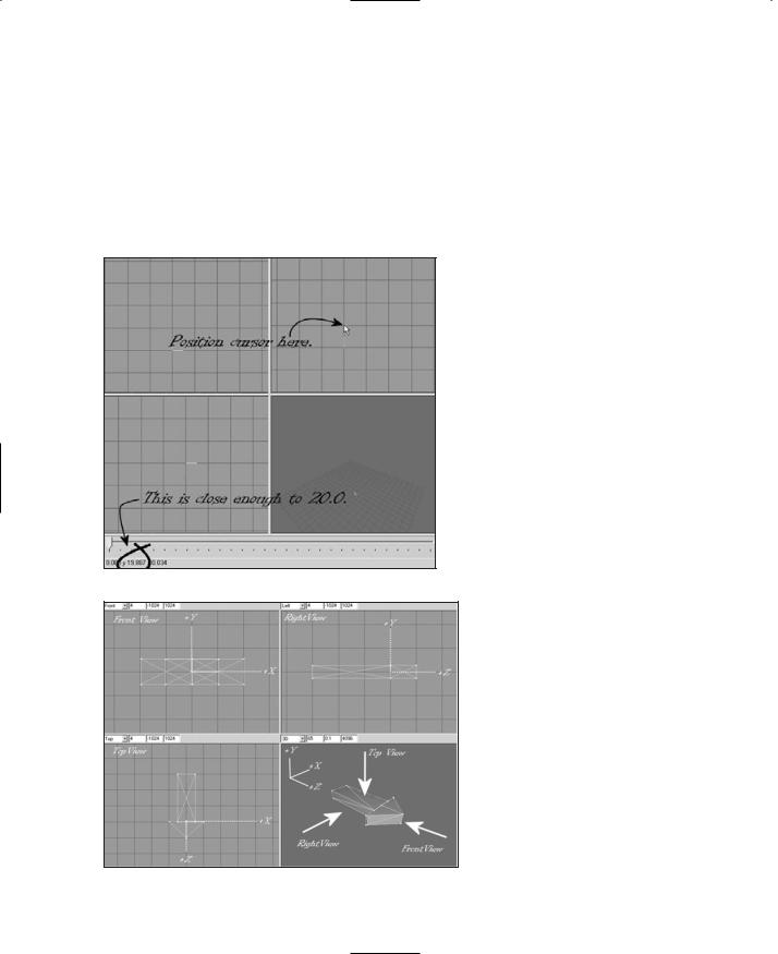
pictures in this book, the Y-axis line is cyan and the Z-axis line is magenta. The place where these two lines meet is the (0,0,0) coordinate in object space. Hold your mouse cursor over the first grid line above the (0,0,0) location and look down to the lower-left corner of the MilkShape window while keeping your cursor over that grid line. You should see the Y-axis value at about 20.0 or so (see Figure 13.3). If you see 20.005 or 19.885, that's good enough. If you don't see 20.0 or so, zoom the view in or out until you do. Adjust your other two wireframe views to the same scale. If you position your cursor one grid line directly above the (0,0,0) point on the Front view (upper left), you should see the 20.0 or so also for the Y value,
Figure 13.3 Checking the zoom in the Right Side view.
Figure 13.4 Torque-oriented object in the MilkShape viewports.
but for the Top view, the same relative positioning will be affected in the Z-axis.
Figure 13.4 contains various notations to help you understand the coordinate display system. In this figure, I've left in MilkShape's viewport labels above each viewport's frame in order to illustrate the variation that emerges with the Torque Right Side view being seen in MilkShape's Left viewport.
The whole point of this little exercise is to expose you to the coordinate display and to ensure that your layout matches the one we'll be working with here. Of course, at times when you zoom in and out this might change, but now you have a method of recalibrating when
necessary.
The Soup Can Revisited
Now that you have a bit of a grasp of what you are looking at in the GUI, and how to move your views around to look at your model, we'll move on to actually creating a quick model to get your feet wet. There's nothing like doing for learning!
Team LRN
MilkShape 3D |
385 |
Creating the Basic Shape
A closed can is a cylinder. A cylinder is what we call a primitive shape, like a sphere or a cube. The primitives are added together in various ways to build up more complex shapes.
1.Choose the Model tab in the toolbox.
2.Click on Cylinder.
3.Position your cursor in the Right Side view about three grid lines above (0,0,0) and one grid line to the left. Click and drag down and to the right until your object looks like Figure 13.5.
4.Choose the Groups tab. You will see a single group named cylinder01 (it may be a higher number if you made more cylinders and deleted them—MilkShape just adds 1 to the number at the end during its auto-naming).
t i p
You may recall encountering the term mesh way back in Chapter 3. In MilkShape the word group is actually an analogue for the word mesh. They mean essentially the same thing.
5.Click on the group name to highlight it, and then type can in the box to the right of the Rename button where it says "Cylinder01".
6.Click Rename, and the group will now be called can.
7.Choose the Materials tab.
8.Click New.
9.Type label into the Materials Rename box.
10.Click Rename.
11.In the Material frame of the Materials tab you will see two buttons labeled "<none>". These are the texture buttons. The top one assigns the standard texture, and the bottom one allows you to assign a texture whose alpha channel you want to use for this material.
12.Click the top texture button. You will get a file
dialog box. |
Figure 13.5 Making a cylinder. |
Team LRN
386Chapter 13 ■ Introduction to Modeling with MilkShape
13.Browse your way to C:\3DGPAi1\resources\ch9 and double-click the can.jpg file.
14.Now choose the Groups tab again, make sure your cylinder's group is selected in the list. If your can is not already highlighted in red, click Select. You will see your can highlighted in red in the three wire-frame views.
15.While your can is still selected, switch back to the Materials tab, choose your new material in the list, and click Assign.
t i p
If your screen resolution is set to 800 600 or less, you will not be able to see the entire Assign or Select By buttons. The top one-quarter or so of those buttons is just visible on the bottom-right corner. Assign is located below the Rename button, and Select By is located below the edit box that is to the right of the Rename button.
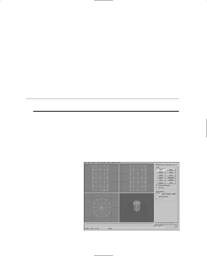
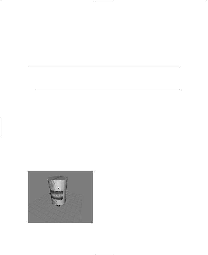
16.Right-click in the 3D view and choose Textured. Your can should appear with the texture wrapped around it, like in Figure 13.6.
17.Save your work so far as mynewcan.ms3d somewhere, by choosing File, Save As.
18.In preparation for UV unwrapping the can object, choose File, Export, Wavefront Obj and export the file to C:\3DGPAi1\resources\ch9\mynewcan.obj.
Okay, so we have the soup can made, and we've assigned the texture to it. The reason the texture doesn't fit right yet is because the texture coordinates haven't been mapped to the object yet. That's our next step.
UV Unwrapping the Can
In Chapter 9 we encountered some of the theory and process behind UV unwrapping and mapping. In a later section in this chapter we'll go into more theory, as well as more detail about the UVMapper tool. For our purposes at the moment, we just want to get the texture skin
mapped correctly onto the can.
|
Whether the skins are created before the object |
|
|
or the object is created first will probably change |
|
|
from project to project or even from phase to |
|
|
phase within a project. At this point in the book, |
|
|
we already have a skin—can.jpg—so we want to |
|
|
make sure the can will unwrap to match the |
|
|
skin. This isn't a problem in this case. It may be |
|
|
a problem with other projects though, so be |
|
Figure 13.6 Assigned texture. |
||
aware of that possibility. |
Team LRN
MilkShape 3D |
387 |
1.Using Windows Explorer, browse your way to C:\3DGPAi1\resources\tools and launch UVMapper.exe.
2.Maximize the window when it opens.
3.Find the file you exported, C:\3DGPAi1\resources\ch9\mynewcan.obj, and open it.
4.You will see an alert, listing some statistics about the object. Click OK.
5.You will see a bunch of triangles fill your window. Ignore them for the moment.
6.Choose Edit, New UV Map, Cylindrical Cap. You will get a Cylindrical Cap Mapping dialog box.
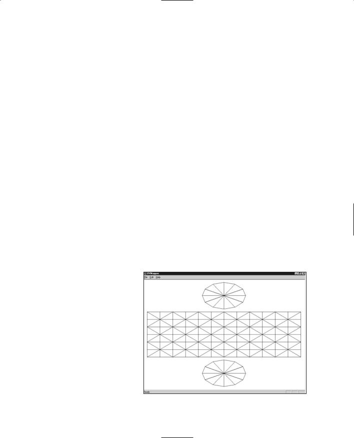
7.Click OK. You will then get a layout of the can's triangles (like that in Figure 13.7), with a rectangular block of triangles across the middle and a circle of triangles at both top and bottom.
8.Choose File, Save Model. The OBJ Export Options dialog box then appears.
9.Set the options boxes as shown in Table 13.1 and click OK.
10.Replace the OBJ file C:\3DGPAi1\resources\ch9\mynewcan.obj by saving over it.
11.Choose File, Save Texture Map. The BMP Export Options dialog box appears.
12.Set the options to the values shown in Table 13.2.
13.Save to the file name C:\3DGPAi1\resources\ch9\mynewcan.bmp. This is the texture map, or UV mapping template, for your can.
14.Switch back to MilkShape.
15.Choose the Groups tab and select the can group.
16.Click the Delete button. You will replace this object with the one you exported from UVMapper.
17.Choose File, Import, Wavefront Obj and import the mynewcan.obj file you saved from UVMapper.
18.On the Groups tab, locate your new object (mynewcan.obj), select it, and rename it if you like.
19.With the new object selected, choose the Materials tab.
20.Choose the label mater-
ial and then click Assign. |
Figure 13.7 Unwrapping the can in UVMapper. |
Team LRN