Theoretical Calculations and Numerical Modeling 349
For the prediction of NOx formation, the extended Zeldovich mechanism described by Heywood[603] was implemented. The soot emission model is a modified version of previously published models for soot formation and oxidation. Details of the soot emission model have been discussed by Han et al.[604]
5.3.0MODELING OF DROPLET PROCESSES OF MELTS
As for normal liquids, modeling of droplet processes of melts provides tremendous opportunities to improve the understanding of the fundamental phenomena and underlying physics in the processes. It also provides basic guidelines for optimization and on-line control of the processes. This section is devoted to a comprehensive review of process models, computational methods, and numerical modeling results of the droplet processes of melts. The emphasis of this section will be placed on the droplet processes in spray atomization for metal powder production, and spray forming for near-net shape materials synthesis and manufacturing. Details of these processes have been described in Ref. 3.
Several basic process stages are common in these droplet processes: (a) metal and gas delivery, (b) atomization, and (c) spray. Droplet cooling, solidification and microstructure evolution may start as early as in the atomization stage and continue in the spray stage. In spray forming and thermal spray processes, droplet deposition, cooling and consolidation on target substrate is an important final stage. A more detailed review of modeling studies on this stage has been given in Ref. 3, and hence this section will concentrate on more common phenomena, i.e., droplet-substrate interactions.
The fundamental issues to be addressed in the process modeling include spray enthalpy, gas consumption, spray mass distribution, microstructure of solidified droplets, and droplet-substrate interactions. The effects of atomization gas chemistry, alloy composition and operation conditions on the resultant droplet properties are also to be investigated in the process modeling.
350Science and Engineering of Droplets
5.3.1Modeling of Melt Flows and Heat Transfer in NearNozzle Region
In spray atomization and spray forming processes, a liquid metal is normally transported from a melting crucible (tundish) to an atomizer through a delivery nozzle. During the flow in the delivery nozzle, the melt temperature decreases gradually due to the heat exchange with the nozzle wall. Premature solidification of the melt in the delivery nozzle (a phenomenon referred to as freeze-up) may occur when the melt temperature decreases down to or below its melting temperature. The freeze-up may be caused by: (a) inadequate melt superheat; (b) excessive residence time of the melt in the delivery nozzle; and/or (c) recirculation of undercooled droplets at the nozzle exit. The selection of appropriate melt superheat requires that it can offset the heat loss of the melt during the flow in the delivery nozzle. The heat loss and the residence time of the melt are closely related to its flow and heat transfer behavior in the nozzle.
The mass flow rate of a liquid metal through a delivery nozzle orifice may be calculated with the following equation:[605]
Eq. (6) m& L = cAL ρ L (2gh + 2 PL / ρL )1 / 2
where c is the nozzle discharge coefficient, AL is the cross-sectional area of the liquid nozzle orifice, g is the gravitational acceleration, h is the metal head, and PL is the overpressure. The nozzle discharge coefficient is unity for an ideal flow and decreases with increasing melt viscosity. For l0/d0 ≤ 4, c ≈ 0.62; for l0/d0 > 4, c ≈ 0.82.[605] The overpressure may be caused by applying a pressure differential between melting chamber and spray chamber for free-fall atomizers, or by the suction at the nozzle base for close-coupled atomizers.[325] In absence of an overpressure, the metal head should be maintained constant by pouring molten metal from a melting tundish into a pouring tundish during atomization in order to maintain a constant metal flow rate.
Theoretical Calculations and Numerical Modeling 351
Modeling of melt flow and heat transfer in the near-nozzle region is required to predict the process parameters necessary for preventing the premature solidification of liquid metals/alloys and to determine the optimum atomizer parameters. The modeling results of the metal delivery stage also provide initial conditions for the modeling of the ensuing atomization stage.
Liu et al.[606][607] developed a numerical model and computer code on the basis of the boundary layer theory and the modified van Driest and Cebeci mixing length turbulence model to simulate the flow and heat transfer of molten metals in a delivery nozzle. Numerical calculations were conducted for liquid Al, Cu, Mg, Ni, Ti, W, In, Sn, Bi, Pb, Zn and Sb to study the effects of process parameters and material properties on the minimum melt superheat that is necessary to prevent the freeze-up during delivery of the molten metal prior to atomization. To facilitate the application of the numerical model and to provide direct insight into the complex relationship among the minimum melt superheat, process parameters and material properties, processing maps were developed on the basis of the modeling results, as shown in Fig. 5.1.
The processing maps can be used to select the process conditions that are necessary to avoid the freeze-up. From the processing maps it can be seen that within the range of low overpressure values (for example, PL ≤ 60 kPa), increasing the overpressure can effectively decrease the minimum melt superheat, especially for a large nozzle length to diameter ratio (for example, l0 /d0 = 17) and for materials of low densities (for example, Al and Mg). This effect diminishes with further increase in overpressure. The minimum melt superheat can be decreased by reducing the nozzle length to diameter ratio, by selecting a smooth delivery nozzle with low thermal conductivity and thick nozzle wall, by imposing a high overpressure, and/or by enhancing atomization gas temperature. The overpressure, which is necessary to avoid the freeze-up (referred to as minimum overpressure), decreases with decreasing nozzle length to diameter ratio or decreasing melting-temperature to gas-temperature ratio.
Theoretical Calculations and Numerical Modeling 353
The modeling results showed that for the materials studied, the minimum melt superheat ranges from 0.005Tm to0.19Tm, depending on process parameters and material properties. The dependence is quantitatively expressed in a correlation derived from a regression analysis of the numericalresults:
|
DT |
é |
μ |
L |
U |
2 |
|
T |
m |
ù0.1 é l |
0 |
ù0.3 |
||
Eq. (7) |
|
= 0.15ê |
|
|
heat |
|
|
ú |
ê |
|
ú |
|||
Tm |
|
|
|
|
|
|
|
|
|
|||||
|
êkL c pL ρ L DPL |
|
TG ú |
ë d0 |
û |
|||||||||
|
|
ë |
|
|
|
|
|
|
û |
|
|
|
|
|
where T is the melt superheat,Tm is the equilibrium melting temperature of metal, µL, kL, cpL, and ρ L are the kinematic viscosity, thermal conductivity, thermal capacity, and density of liquid metal, respectively, Uheat is the overall heat transfer coefficient between liquid metal at tube wall and atomization gas, PL is the overpressure, TG is the gas temperature, and l0/d0 is the nozzle length to diameter ratio.
In this correlation, the material properties are evaluated at the melting temperature. The left hand side of the correlation is the dimensionless minimum melt superheat. The right hand side of the correlation is also dimensionless, and represents a combination of the Prandtl number, Euler number, Reynolds number and Nusselt number, as well as temperature and length ratios Tm/TG and l0/d0. The correlation is accurate within 10%. In addition, considering the effects of the surface roughness of nozzle wall, the pre-basal coefficient in the regression expression has been increased by 25% in order to predict a safe estimate of the minimum melt superheat.
The above correlation can be used directly to calculate the process conditions that are necessary to avoid the freeze-up. From this correlation, it is evident that materials with high thermal conductivity, high thermal capacity and/or large density allow small minimum melt superheat, whereas materials with high melting temperature and/or high viscosity require large minimum melt superheat. For materials with high surface tension, the minimum melt superheat calculated with this correlation represents an upper bound.
354 Science and Engineering of Droplets
In addition to the above process parameters, atomizer geometry and configuration also influence the minimum melt superheat by altering gas flow pattern and distribution. The freeze-up may occur even for the melt superheats that are higher than the predicted minimum value, if recirculation gas flow forms in the exit region of the delivery nozzle. The recirculation gas flow in this region may drag relatively cool or undercooled droplets upwards, and deposit them on the tip of the delivery nozzle, where they eventually solidify. The solidified metal may continue to increase in thickness during atomization, eventually choking the melt flow, a phenomenon that has been described previously as freeze-up. Therefore, the minimum melt superheat calculated with the above correlation is only a necessary condition, rather than a sufficient condition. The sufficient condition to avoid the freezeup must be determined by examining the flow field below the delivery nozzle. If the geometry and configuration of the delivery nozzle and atomization gas nozzles are arranged in such a manner that the recirculation gas velocity is not large enough to drag cool droplets up to the delivery nozzle tip, then employing the melt superheat calculated with the above correlation may avoid the freeze-up. Accordingly, for freefall atomizers, in order to minimize the probability of the freeze-up, it is necessary to design the atomizer geometry and select the position of the delivery nozzle in such a way as to minimize the formation of the recirculation gas flow in the region below the delivery nozzle. However, for close-coupled atomizers, the recirculation gas flow is utilized to generate a thin liquid film and sheet prior to atomization, as discussed previously in the liquid film-sheet breakup mechanism.
The temperature of a liquid metal stream discharged from the delivery tube prior to primary breakup can be calculated by integrating the energy equation in time. The cooling rate can be estimated from a cylinder cooling relation for the liquid jet-ligament breakup mechanism (with free-fall atomizers), or from a laminar flat plate boundary layer relation for the liquid film-sheet breakup mechanism (with close-coupled atomizers).
Theoretical Calculations and Numerical Modeling 355
5.3.2Modeling of Gas Flows in Near-Nozzle Region
In spray atomization and spray forming processes, the distribution of velocity and temperature of atomization gas in the near-nozzle region determines the impact kinetic energy and cooling effect on the molten metal stream, and hence significantly influences the generation, initial size, shape, radial distribution and flight direction of droplets. On the other hand, the melt flow and heat transfer during delivery and atomization determine its temperature, viscosity and surface tension, which in turn affect the continuous operation of the delivery nozzle and the droplet size distribution. Therefore, the flows and heat transfer during metal and gas delivery and in the vicinity of the atomizer are critical to the atomization efficiency and gas consumption, and have a significant impact on the distributions of droplet size, spray enthalpy and spray mass.
For the delivery of atomization gas, different types of nozzles have been employed, such as straight, converging, and convergingdiverging nozzles. Two major types of atomizers, i.e., free-fall and close-coupled atomizers, have been used, in which gas flows may be subsonic, sonic, or supersonic, depending on process parameters and gas nozzle designs. In sonic or supersonic flows, the mass flow rate of atomization gas can be calculated with the following equation based on the compressible fluid dynamics:
|
|
|
æ 2 ö( γ+1) / 2( γ−1) |
æ |
g |
ö1/ 2 |
||
Eq. (8) |
m& |
= A P |
ç |
|
÷ |
ç |
|
÷ |
|
RT |
|||||||
G |
G G 0 |
ç g +1 |
÷ |
ç |
÷ |
|||
|
|
|
è |
|
ø |
è |
G 0 |
ø |
where AG is the cross-sectional area of the gas nozzle, PG0 and TG0 are the gas pressure and temperature in the supply manifold, respectively. The values of the gas constant R and the isotropic factor of gas γ can be found in Table 2.7 for various gases.
The power requirement for pressurizing atomization gas may be estimated using the following expression:
Eq. (9) |
Power = m&G RM GTG 0 ln(PG 0 / Pchamber ) |
356 Science and Engineering of Droplets
where Pchamber is the gas pressure in spray chamber, and the values of the molecular weight of gas,MG , are given in Table 2.7 for various gases.
While the gas flow in the nozzle can be calculated on the basis of isentropic expansion of stagnation properties, the analysis of gas flows in the near-nozzle region can be performed by means of numerical simulation/modeling using computational fluid dynamics (CFD) codes. Such codes can generally solve incompressible and/or compressible flows, and the k-ε two-equation model is frequently used as turbulence model. The modeling of the flow and temperature fields of atomization gas in the near-nozzle region provides basic guidelines for optimization of atomizer parameters. The modeling results of this stage also provide initial conditions for the modeling of the ensuing atomization stage.
Recently, there has been an increasing number of numerical studies on the gas delivery stage[161][163][324][325][496][608] and some experimental measurements in the near-nozzle region.[160][162][169][170] [177][327][608]-[610] Extensive theoretical,[611] numerical,[161] and experimental[170][175] studies on high-speed gas jet flows in the near-nozzle region have been conducted to investigate velocity profiles, pressure distributions, shock waves and flow structures.
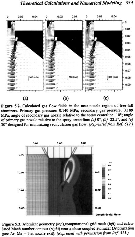
Espina et al.[611] applied the method of characteristics based on the Prandtl-Meyer theory to analyze gas flows near a close-coupled atomizer. The analysis was aimed at understanding the complex flows, determining the values of aspiration pressure, and locating the shock waves. The theoretical calculations explained the measured aspiration behavior and provided a potential tool for evaluation of different atomizer geometries, gases and pressure ratios. The theoretical analysis also provided a means for examining and optimizing the geometric design of gas atomizers and correlating the geometric design parameters to atomization efficiency. In addition, several interesting conclusions were drawn from the theoretical calculations. First, the energy dissipated in the flow interactions between discrete jets requires a higher operational pressure than that required by an annular jet to achieve the maximum of aspiration. This reduction in the operational pressure when using an annular-jet atomizer may decrease the gas mass flow rate required for the atomization

Theoretical Calculations and Numerical Modeling 357
of molten metals. Second, the maximum of aspiration in an annular-jet atomizer is of lesser magnitude than in a discrete-jet atomizer. This reduction in the aspiration may reduce the liquid metal flow rate during atomization. Third, the good agreement between the calculated and experimental results suggested that the errors caused by neglecting turbulent effects are small in this type of flows.
See and Johnston[319] studied the gas velocity profiles generated by ring atomizers with multiple discrete jets. In the atomization experiments of molten lead by See et al.,[318] a ring atomizer with four discrete jets was used to impinge the liquid stream on the centerline at different angles. The following empirical equations developed originally for a single submerged gas jet were used to calculate the gas velocity at the breakup point:
Eq. (10)
Eq. (11)
UGc |
æ dG0 |
ö |
||
|
= 6.2ç |
|
÷ |
|
UG 0 |
l |
|||
è |
ø |
|||
æ U |
Gc |
ö |
|
logçç |
|
÷÷ =UG 0 |
|
|
|
||
è UGr |
ø |
||
æ r ö2 ç ÷ è l ø
for |
7 < |
l |
< 100 |
|||
d G 0 |
||||||
|
|
|
|
|||
|
|
|
|
|
||
for |
7 < |
l |
<100 |
|
||
|
|
|||||
|
|
dG0 |
|
|
||
where UGc is the gas velocity on the jet center line at a distance l from the gas nozzle exit, UG0 is the initial gas velocity at the gas nozzle exit, dG0 is the gas nozzle diameter, and UGr is the gas velocity at a radius r from the jet axis.
Liu[325][612] performed numerical modeling of gas flows in the near-nozzle region for both the close-coupled and free-fall atomizer configurations. The flow fields involved subsonic and supersonic flows, turbulence, shock waves, free shear flows, and recirculation flows. In view of the complex gas flows during atomization, the full Reynolds-averaged Navier-Stokes equations were solved along with turbulence transport equations.[613] The effect of turbulence was modeled using the standard Boussinesq approximation. Two turbulence models, i.e., combined Thomas/Baldwin-Lomax model and k-ε two-equation model, were used, switching from the former to the latter
358 Science and Engineering of Droplets
after some iterations. These models can accurately predict both wall bounded flows and free shear flows.[613]
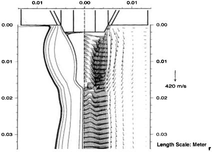
The calculated gas velocity distributions for a free-fall atomizer configuration in different nozzle geometries are shown in Fig. 5.2. The results suggested that for a constant gas pressure, the recirculation gas flow can be minimized by arranging the geometry of a free-fall atomizer. For a close-coupled atomizer configuration, the calculated Mach number contour is shown in Fig. 5.3 and the calculated gas velocity vectors and stream lines are illustrated in Fig. 5.4. The gas flow is choked at the nozzle exit (Ma = 1), and then expands into the atomization chamber while the Mach number reaches a maximum of about 6. The supersonic gas flow separates at the corner of the metal delivery nozzle, leading to the formation of an annular free jet and a recirculation region between the delivery nozzle tip base and the realignment point where the centerline velocity vanishes. The gas velocity in the recirculation region is relatively low, and the gas flows up towards the delivery nozzle tip and then turns outwards along the delivery nozzle base plane, as clearly demonstrated by the stream lines in Fig. 5.4. The gas pressure attains a maximum at the center of the nozzle tip base and decreases to a minimum away from the center in radial direction. It is this pressure gradient and the recirculation gas flow that cause the radial flow of liquid metal, forming a thin liquid film and then a thin liquid sheet prior to primary breakup. Therefore, the strong recirculation flow and the adjacent free shear flow are responsible for the liquid film-sheet breakup mechanism, and critically affect the resultant droplet properties, as will be discussed in the next subsection.
The recirculation region has been experimentally observed in the gas flow fields generated using this type of atomizer configuration[160] or similar atomizer configurations.[169] Mi etal.’s numerical modelingofhigh pressure gas flows near a close-coupled atomizer[161] also demonstrated that downstream of the delivery nozzle there exist a strong recirculation region and an adjacent mixing layer at all gas stagnation pressures, and normal shock structures at some high stagnation pressures. The intensity of the recirculation flow and the mixing layer increases with increasing stagnation pressure.
Theoretical Calculations and Numerical Modeling 361
controlling droplet size distribution, increasing atomization efficiency, and reducing gas consumption.
Although spray forming has been extensively developed for producing preforms from diverse alloy compositions, the difference between atomization processes using different gases (for example, nitrogen and argon) is not well understood, nor has a correlation between process parameters and final part quality been established for spray forming using argon. For example, to convert a spray forming process from using nitrogen to argon, the ratio of mass flow rate of gas to metal has to be doubled according to a rule of thumb based on the differences in the density, heat capacity and thermal conductivity between the gases. However, the spray enthalpy or solid fraction of the spray developed when using the rule of thumb is not comparable, leading to different levels of microstructural characteristics. In order to produce the same microstructure using argon as using nitrogen, to achieve a narrow spray distribution and to reduce total gas consumption for cost-effective manufacturing, it is necessary to investigate atomization mechanisms and ascertain the effects of thermophysical properties and process parameters on atomization processes. Zeng et al.[173][500] and Liu et al.[154][500] studied the influence of gas chemistry on atomization processes of liquid metals. The results showed that gas chemistry critically affects both the size distribution and the thermal history of the atomized droplets.
Over the past decade, a number of numerical studies have been performed to model the liquid metal and gas delivery, spray, deposition, and consolidation stages in spray forming.[18][51][52][154][156][174][338]
[339][378][379][388][389][495][496][606][607][614]-[616] However, only limited
modeling studies have been conducted for the atomization
stage.[161][324][325]
On the basis of the experimental observations,[160][169][327] Liu[325] conceived a liquid film-sheet breakup model for atomization of liquid metals with close-coupled atomizers. In this atomization model, it was postulated that atomization of a liquid metal with a close-coupled atomizer may occur in the following sequence: (1) formation of a liquid film, (2) conversion of the liquid film into a liquid sheet, (3) primary breakup of the liquid sheet into droplets,(4) droplet
362 Science and Engineering of Droplets
deformation and cooling, and(5) secondary breakup and/or solidification of the droplets. Computational methods and a computer code were developed to model liquid metal breakup, droplet dynamics and heat transfer during gas atomization. Empirical and experimental correlations were used along with basic conservation equations to predict the droplet size distribution and eventually the properties of the metal powder produced by gas atomization.
In this numerical model,[325] the flow characteristics of the liquid metal film were calculated on the basis of a force balance under the assumption of a steady-state Couette flow. These flow characteristics along with the empirical correlation suggested by Eroglu et al.[262] were used to estimate the mean sheet length, assuming that the sheet trajectory follows the gas stream line prior to primary breakup. The Sauter mean diameter of the droplets after primary breakup was calculated using Knoll and Sojka’s semi-empirical correlation.[263] The droplet size distribution after primary breakup and prior to any secondary breakup was described by Simmons’ universal root-normal distribution function. In this distribution, a straight line can be generated by plotting (D/MMD)0.5 vs. cumulative volume of droplets on a normal-probability scale. The slope of the straight line can be specified by the ratio MMD/SMD that may take a value of 1.1, 1.2 or 1.5.[249] After primary breakup, the droplets cool while they accelerate in the gas flow field. The droplet trajectories were calculated using Thomas’ 2-D equation of motion for a sphere[579] with some simplifications.[154][156] Henderson’s formulations[575] were used for the calculation of drag coefficients of a sphere in subsonic and supersonic gas flows. The effect of droplet distortion on the drag coefficients was estimated with the experimental results in Ref. 285. The heat transfer between the droplets and atomization gas leads to rapid cooling and eventual solidification of the droplets, terminating the deformation and further breakup of the droplets. Due to the small Biot number, a uniform droplet temperature was assumed and the lumped parameter model[156] was used. Convection and radiation were considered in the heat transfer model. The heat transfer coefficient was calculated using the Ranz-Marshall correlation[505] after appropriate modifications.[154][156]
Theoretical Calculations and Numerical Modeling 363
Following primary breakup, the droplets deform and may further break up, depending on their interactions with the atomization gas. To determine if a droplet will undergo secondary breakup in addition to deformation, the breakup regime map developed by Hsiang and Faeth[285] was used. The time scale and degree of deformation prior to secondary breakup as well as the Sauter mean diameter of droplets after secondary breakup were calculated using the correlations suggested by Hsiang and Faeth.[285] The droplet size distribution after secondary breakup also follows the Simmons’ root-normal distribution pattern with MMD/SMD taking a value of 1.1, 1.2 or 1.5.[285] Similarly to primary breakup, once SMD was calculated, the entire droplet size distribution after secondary breakup could be determined. Following secondary breakup, no further breakup was considered since no evidence of subsequent breakup was found in the experiments.[285]
The solution of the gas flow and temperature fields in the nearnozzle region (as described in the previous subsection), along with process parameters, thermophysical properties, and atomizer geometry parameters, were used as inputs for this liquid metal breakup model to calculate the liquid film and sheet characteristics, primary and secondary breakup, as well as droplet dynamics and cooling. The trajectories and temperatures of droplets were calculated until the onset of secondary breakup, the onset of solidification, or the attainment of the computational domain boundary. This procedure was repeated for all droplet size classes. Finally, the droplets were numerically sieved and the droplet size distribution was determined.
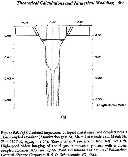
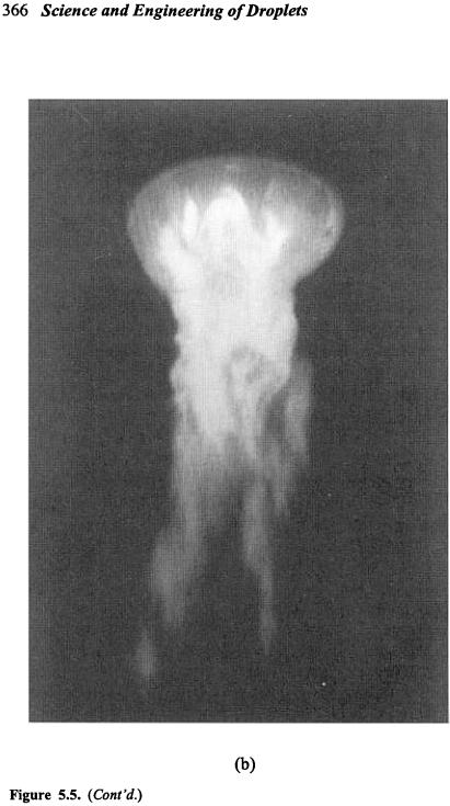
The modeling results suggested that gas atomization of aliquid metal with a close-coupled atomizer may occur in the following sequence, as illustrated by the calculated trajectories of the liquid metal sheet and droplets in Fig. 5.5 (a). Initially, the liquid metal flows downwards through the delivery nozzle. At the exit of the nozzle, it changes its flow direction to radially outwards along the nozzle base plane, forming a thin liquid film. The formation of the liquid film is caused by the interaction between the liquid metal and the gas flow in the recirculation region. It is also this interaction that leads to the
364 Science and Engineering of Droplets
turning of the liquid film at the edge of the nozzle base plane into a liquid sheet which extends downwards following gas stream lines. This is followed by the primary breakup of the sheet into droplets. The droplets accelerate, deform, and cool in the gas flow field. The trajectories of small droplets also follow the gas stream lines closely. Secondary breakup of the droplets may occur, depending on their deformation and cooling/solidification rates. This liquid film-sheet breakup mechanism may be considered as one of the operating atomization mechanisms in gas atomization processes with close-coupled atomizers.
Using this model and computer code, the calculated sheet and droplet trajectories showed a good qualitative agreement with high-speed video imaging of actual gas atomization processes,[160][327] as evident in Fig. 5.5. The code-predicted droplet size distribution is also in a fairly good agreement with the experimentally measured distribution,[163][164] with the calculated droplet size distribution narrower than the measured data. Droplet coalescence caused by collision and aggregation, particularly in the vicinity of the spray centerline, may explain this discrepancy.
Droplet collision is a phenomenon inherent in the dense region of a spray. Droplet collisions may lead to local agglomeration that affects the droplet size distribution. There have been considerable efforts in modeling droplet-droplet collisions and coalescence,[229] but the models are still not generally applicable.[576] Moreover, the calculations in the dense region of a metal spray is much more complicated than in a diesel spray because the physical phenomena and mechanisms in the dense region are not well understood.
Regarding the effects of process parameters on gas atomization of melts, modeling and experimental studies[163][164][324] revealed that the mass median droplet diameter decreases with increasing atomization gas pressure and gas to metal mass flow rate ratio. The standard deviation decreases with increasing gas to metal mass flow rate ratio. As the melt superheat increases, both the mass median droplet diameter and the standard deviation decrease.