

Empirical and Analytical Correlations 253
4.2.0CORRELATIONS FOR DROPLET SIZES OF NORMAL LIQUIDS
In many atomization processes, physical phenomena involved have not yet been understood to such an extent that mean droplet size could be expressed with equations derived directly from first principles, although some attempts have been made to predict droplet size and velocity distributions in sprays through maximum entropy principle.[252][432] Therefore, the correlations proposed by numerous studies on droplet size distributions are mainly empirical in nature. However, the empirical correlations prove to be a practical way to determine droplet sizes from process parameters and relevant physical properties of liquid and gas involved. In addition, these previous studies have provided insightful information about the effects of process parameters and material properties on droplet sizes.
The process parameters influencing droplet sizes may include liquid pressure, flow rate, velocity ratio of air to liquid (mass flow rate ratio of air to liquid), and atomizer geometry and configuration. It has been clearly established that increasing the velocity ratio of air to liquid is the most important practical method of improving atomization.[211] In industrial applications, however, the use of mass flow rate ratio of air to liquid has been preferred. As indicated by Chigier,[211] it is difficult to accept that vast quantities of air, that do not come into any direct contact with the liquid surface, have any influence on atomization although mass flow rates of fluids include the effects of velocities.
The liquid properties of primary importance are density, viscosity and surface tension. Unfortunately, there is no incontrovertible evidence for the effects of liquid viscosity and surface tension on droplet sizes, and in some cases the effects are conflicting. Gas density is generally considered to be the only thermophysical property of importance for the atomization of liquids in a gaseous medium. Gas density shows different influences in different atomization processes. For example, in a fan spray, or a swirl jet atomization process, an increase in the gas density can generally improve
254 Science and Engineering of Droplets
atomization for a constant liquid flow rate.[116] However, beyond a certain limit, a further increase in the gas density may increase droplet size due to the reduced relative velocity resulted from the increased drag. In gas atomization of melts, using a lighter gas, for example, helium, to replace air can improve atomization for a constant gas pressure.
In the following sections, the correlations for droplet sizes generated by different types of atomizers will be summarized, and the effects of process parameters and material properties on droplet sizes will be discussed on the basis of the analytical and experimental studies available in published literature.
4.2.1Pressure Jet Atomization
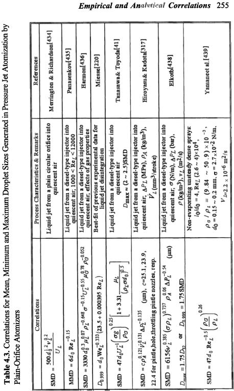
Various correlations for mean, minimum and maximum droplet sizes generated in pressure jet atomization using plain-orifice atomizers have been derived,[434]-[439] as listed in Table 4.3. In these correlations, d0 is the diameter of discharge orifice, vL is the kine-
·
matic viscosity of liquid, μ G is the dynamic viscosity of gas, VL is the volumetric flow rate of liquid, and Cf is the skin friction coefficient. The Jet Reynolds number and Weber number are defined as ReL = ULρ Ld0/µL and WeL = UL2ρ Ld0/σ , respectively. The primary parameters governing the mean droplet size are liquid injection pressure or velocity, physical properties of liquid (viscosity, density, surface tension), and ambient gas (viscosity, density), and atomizer geometry parameter such as discharge orifice diameter. Some other parameters that may influence the droplet size include relative velocity, ambient gas pressure and temperature, geometrical boundaries that confine the surrounding atmosphere (chamber walls), presence of nearby jets, chemical reactions (combustion), as well as nozzle and supply-line configurations.[220] In spray combustion applications, the density and surface tension of most commercial fuels differ only slightly from each other (Table 2.2) so that the significance of these properties is weak. However, the viscosity of different fuels spans a large range and may vary by nearly two orders of magnitude. Thus, the viscosity exhibits a significant effect on the mean droplet size.
>-
.0
§
..p
~
N
.§
0
<
~
~
~
C/)
C/)
£
.s
~
"'td
~
~
C/)
~
00
-~ P.
a
1
~
]
~
~
~~
~
I-.
~
§~
.~ |
.e |
"U |
o |
6< |
|
u |
Q) |
|
u |
.~ |
|
~8 |
I |
~ |
|
:c |
.§ |
=- |
|
~~ |
|
|
|
|
Empirical |
and An, |
|
Correlations |
255 |
||
|
~ |
|
|
|
|
|
|
|
|
|
('"1 |
|
|
|
~ |
~ |
|
|
|
|
""" |
|
|
|
|
|
|||
|
|
|
|
|
|
|
|||
|
= |
|
|
|
"1' |
|
|
||
|
|
|
|
(0") |
|
|
|||
|
Q |
.,., |
|
|
~ |
|
"0\' |
||
|
"' |
|
|
'"";a |
|
||||
|
'E |
("\ |
(0\10 |
1 QM |
'0 |
|
('\ |
||
I",.. |
~ |
O |
'0 |
'00" |
~ |
||||
oc |
|
|
|||||||
|
|
|
~ |
M |
~ |
"0 |
~ |
'iC |
|
|
-5 |
1 |
.. |
..,. |
|||||
I ~ |
= |
~ |
E-o |
||||||
|
~ |
|
~ |
||||||
01 |
~ |
~ |
O |
UJ |
~ |
1 |
|||
|
~ |
|
|
~ |
v |
||||
OM |
~ |
~ |
.~ |
cc |
~ |
= |
|||
.. |
"' |
~ |
= |
fU |
|||||
~ |
|
0= |
m |
~ |
"' |
~ |
8 |
||
|
§ |
= |
~ |
|
~ |
= |
|||
|
m |
|
>- |
|
fU |
||||
|
0rJ |
£1, |
|
|
= |
0 |
|
>- |
|
|
= |
|
|
|
= |
... |
|
|
|
|
|
|
|
= |
.lE |
|
|
||
|
|
|
|
|
E-t |
|
|
||
01: tJ
~
|
-0 |
|
c |
0 |
|
.. |
|
|
|
.= |
|
- |
-"' |
|
.s |
|
|
rn |
|
= |
=u |
|
|
|||
u |
|
.-0 |
.~~ |
u |
IC |
|
||
~ |
u |
|
...0 |
O |
-; |
|
||
= |
~ |
|
100 |
|
|
'0 |
|
|
a |
.= |
|
UN |
'gg. |
|
|
||
|
.G)= |
-== |
|
|||||
|
0 |
|
= V |
.=... |
|
|
||
|
|
|
=c. |
"' |
-0 |
|
||
|
; |
|
.-'4 |
.~ |
=.- |
|
||
|
|
u |
= |
U-; |
|
|||
|
|
|
|
|||||
rn |
8.!: |
|
G)G) |
c.~ |
|
8.. |
|
|
~ |
Q.~ |
|
.t: |
0Jj |
||||
U |
.= |
!i;'v |
i?;"'a |
uB |
|
|||
--= |
u- |
|
|
|||||
= |
P.= |
|||||||
rn |
= |
Uo |
l u |
"' |
||||
"C |
.-u |
.. |
"'- |
I |
~.~ |
|
||
~o |
|
|||||||
.. |
~ |
u |
(J |
|
|
|||
-"' |
|
~~ |
|
|
u:a"' |
|
||
u |
|
~~ |
|
|
||||
~u |
.9 |
I 0~.-2, |
||||||
=1 |
~ |
~ .. |
IC~ |
|
|
|
||
.. |
|
|
... |
|
|
|
|
|
= |
8C" |
=.- |
=I.: |
|
.~ |
'0 |
||
|
|
|||||||
O |
-~ |
~.~ |
|
U.- |
|
|||
o |
|
0- |
O |
IC |
|
|
||
rn |
~ |
|
~5 |
~~ |
I |
~& |
|
|
|
|
~.- |
|
|||||
rn |
"U |
|
-y |
-~ |
|
0- |
|
|
.. |
|
G)", |
uU |
|
|
|||
|
.-.(J |
|
- |
|
||||
u |
'0 |
G) |
|
|
||||
C |
"C.- |
"Q~ |
|
~ |
|
|||
.. |
.-9 |
.~.~ |
= |
|
|
|||
110 |
.g. |
|
= |
* |
|
|||
|
|
g. |
C'C" |
U |
|
|||
|
|
|
|
|
|
|
||
|
~ |
|
:,:j |
:3 |
|
[D |
|
|
|
|
|
|
|
|
|
||
.s |
|
|
c |
|
~ |
|
|
.=~, |
|
||
.= |
|
|
|
|
|
.. |
|
|
c..~ 01) |
||
-c |
|
|
|||
u |
|
|
"U~ |
|
|
u |
|
|
~-- |
|
|
.6' |
|
A |
.C' |
|
~ |
.;; |
|
~ |
.--u |
|
~ |
P..= |
~ |
u |
|
||
Q., |
|
|
|||
.:e;..or) |
|
~IC |
|
|
|
..:.-N |
|
.p. |
|
|
|
|
- |
|
|
||
u |
= |
1 |
u |
6 |
|
", |
u |
"' |
|
|
|
UU |
|
|
|
|
|
~",M |
|
|
:e1-4eQ, |
||
..'U'-' |
II |
||||
..a |
|
IC |
~ |
||
c8C'>< |
. |
e |
.a |
||
."" |
|
~ |
C |
||
|
~ |
|
|
||
= |
|
Q |
|
|
|
|
|
|
= |
||
u |
|
|
U |
|
|
|
|
|
U |
||
, |
|
|
.-.U |
|
"' |
'0 |
|
"C |
|
||
|
|
|
.-U |
.- |
|
.a. |
|
|
~ |
||
|
|
.S' |
|
g. |
|
..:3 |
|
|
|||
|
i...J |
|
|
||
|
=0 |
|
|
fA |
|
|
|
, |
|
|
|
." |
|
|
~ |
|
M |
|
e |
|
|
|
..,..., .= |
|
.. |
|
I |
|
|
|
|
|
|
.s!a |
|
|
~.O |
|
Z |
|
|
||
|
U |
.0 |
|
|
..,. |
|
M |
|
|
|
|
u'-' |
|
"'uO |
)( |
X. o |
|
fA |
|||
~ |
.5 |
Q} |
'in' |
5 |
|
|
|
|||
|
lu "",M |
|
|
|
,. |
Q\x .t-- |
|
|
M |
|
~ |
~,..::= |
|
>..1 |
OM |
|
|
, |
|||
c |
|
|
|
H |
||||||
.. |
"';'. e |
'-' |
~ |
'0 |
|
.,.. II '0 |
||||
~ |
]"i7:>.!ci |
|
|
|
|
t) |
|
O |
||
|
|
|
|
|
|
|||||
M - e ~u..,...c,=~"ot.fA.. |
|
|
|
, |
|
x |
||||
'-' |
"ou~=u |
|
OJ)~ |
OQ= |
|
"! |
||||
..;.;-E |
|
|
.e |
-.M |
||||||
~ |
= |
.~ |
OJ) = |
.Q\ |
|
Ii |
||||
~ |
|
..= |
..,. |
-,~ |
|
|
||||
1 ° |
|
'-' |
..0 |
|
|
|
|
~ |
||
|
~ |
5 |
~ |
6 |
~ |
|
III |
|
|
~ |
|
~ |
~ |
|
Q.~ |
|
..~ |
|
|
|
|
|
-." |
u |
|
.~,. "-0" |
|
~ . |
|
|
||
|
.~ |
= |
|
~ |
|
|
|
0 |
|
|
|
& |
C' |
|
= |
|
|
0" |
|
|
|
|
~ |
|
|
~ |
|
|
~.g |
|
|
|
|
|
|
N |
|
|
|
|
! |
|
|
|
|
|
"' |
|
|
C\ |
|
|
|
|
|
|
|
C |
|
|
|
|
|
||
|
|
|
6 |
|
|
|
|
|
||
|
|
|
I~ |
|
|
...; |
c. |
|
|
|
|
|
|
|
I~9-.. |
M |
"' |
|
|
|
|
|
|
|
~ |
|
.~ |
... |
~ |
|
|
|
|
|
|
|
|
|
|
||||
|
|
|
6~ |
|
|
...; |
~ |
o |
|
|
|
|
|
|
|
|
1"4 |
|
|
||
|
|
|
"'~ |
|
|
M |
- |
|
|
|
|
|
|
~ |
~i |
~ |
|
|
|||
|
|
|
"' |
Q) |
" |
~ |
~ |
|
|
|
|
|
|
6 |
|
|
\.J |
O |
|
|
|
|
|
|
|
~ |
|
,..:, |
= |
-0 |
~ |
|
|
|
|
~ |
..., |
~ |
0 |
|
|||
|
|
|
~ |
~ |
o~ |
"' |
|
|||
"' |
|
|
~ |
0- |
... |
9.= |
|
~ |
t': |
|
|
|
c |
ot1 |
(0} |
|
|
||||
= |
|
|
0 |
'-' |
= |
... |
- |
-0 |
||
c |
|
|
I |
O |
~ |
|
.s. |
|
||
|
|
b |
0: |
+ |
|
... |
|
"! |
||
-.= |
|
|
""' |
|
||||||
|
|
00 |
o |
|
Otj |
d |
|
|
||
= |
|
|
|
|
= |
|
|
|||
'U |
|
|
~ |
+ |
|
|
- |
|
0 1 ~ |
|
|
|
"' |
6 |
= |
~ |
|
||||
.. |
|
|
6 |
"! |
N |
|
||||
.. |
|
|
I~ |
C |
|
|
~ |
|
~~ |
|
c |
|
|
ot1 |
I~ |
e |
|
||||
u |
|
"' |
~ |
:--- |
|
|
'" |
|||
|
|
~ |
.= |
~ |
|
|||||
|
|
r-. |
.!:J.- |
|
|
"' |
||||
N |
|
c |
c |
... |
~I~ |
--. |
~ |
"' |
|
c |
|
6~ |
... |
|
00 |
|
|||||
6-4 |
|
I ~ |
..,~ |
... |
'' |
6~ |
Q |
|
|
I ~ |
:.. |
|
|
c:i |
i~ |
C~ |
|
U |
|||
N |
~ |
~ |
Qc |
I~ |
.~ |
.=. |
:.. |
|
~ |
|
..;0 |
~ |
Q) |
~c |
-~ |
|
|
|
0 |
||
~ |
0 |
~ |
~ 0 |
~ |
= |
I ~ |
|
|||
O |
|
~ |
|
"'3 |
.'-= |
= |
|
|
~ |
|
O |
|
10 |
~ |
~ |
r-.. |
°~ |
.s. |
|
|
t"- |
or- |
1 |
II |
|
|
~ |
|||||
|
~ |
" |
~ |
\.J .. |
1 ~ |
|
II |
|||
|
II |
|
II |
II |
" |
~ |
|
|||
|
|
0- |
|
|
|
|||||
|
|
|
|
0- |
|
|
|
|
|
|
|
~ |
~ |
~ |
"' |
~ |
~ |
~ |
|
|
~ |
|
cf |
~ |
Q |
~ |
||||||
|
rj\ |
|
ri) |
tn |
fI) |
M |
r~ |
|
||
256 Science and Engineering of Droplets
Generally, an increase in liquid injection pressure (velocity) can promote jet breakup due to the increase in both the level of turbulence in the jet, and the aerodynamic drag forces between the jet and ambient gaseous medium. An increase in liquid viscosity resists the breakup of liquid jet and ligaments, and thus, delays the onset of atomization. Therefore, the mean droplet diameter is proportional to the liquid viscosity, gas viscosity, discharge orifice diameter[41] and volumetric flow rate of liquid, and inversely proportional to the liquid density, velocity and injection pressure,[41] with different proportional power indices representing the significance of each factor. However, different researchers reported distinctly different effects of liquid surface tension and gas density on droplet size. An increase in liquid surface tension typically increase the mean droplet size.[220][437][438] On the other hand, Harmon’s[436] correlation suggested that an increase in liquid surface tension may reduce the mean droplet size. An increase in gas density can probably promote secondary breakup of large droplets, and reduce the maximum droplet size, improving the fineness,[41][436] and uniformity of entire droplet sizes, while the effect of gas density on the minimum droplet size seems to be little.[440] In contrast, some correlations[317][438][439] suggested that an increase in the gas density may increase the mean droplet size, plausibly due to the reduced relative velocity resulted from the increased drag. Moreover, Miesse’s experimental results[220] revealed that the effects of flow conditions and physical properties on the maximum droplet diameter depend on the liquid Reynolds number. For example, an increase in jet velocity decreases the maximum droplet diameter for ReL < 11.9 × 10⁴, but increases it for larger values of the Reynolds number. Similarly, an increase in liquid density decreases the droplet diameter for ReL < 2.975 × 10⁴, but increases it for larger values of the Reynolds number.
In addition to these physical properties and process variables, the flow, flow direction, and shock wave of ambient air/gas relative to liquid jet may significantly influence the resultant droplet size distribution. In high-speed aerodynamic atomization, different flow arrangements have been used,[244] including: (a) injection of liquid
Empirical and Analytical Correlations 257
jet into a subsonic or supersonic co-flow, or subsonic contra-flow of air/gas, (b) transverse injection of liquid jet into a subsonic or supersonic crossflow of air/gas, and (c) shattering of liquid jet by a traversing shock. Fine droplets can be obtained as a result of the intense shear at the liquid-gas interface by high-speed gas flow.
Recently, Razumovskii[441] studied the shape of drops, and satellite droplets formed by forced capillary breakup of a liquid jet. On the basis of an instability analysis, Teng et al.[442] derived a simple equation for the prediction of droplet size from the breakup of cylindrical liquid jets at low-velocities. The equation correlates droplet size to a modified Ohnesorge number, and is applicable to both liquid-in-liquid, and liquid-in-gas jets of Newtonian or nonNewtonian fluids. Yamane et al.[439] measured Sauter mean diameter, and air-entrainment characteristics of non-evaporating unsteady dense sprays by means of an image analysis technique which uses an instantaneous shadow picture of the spray and amount of injected fuel. Influences of injection pressure and ambient gas density on the Sauter mean diameter and air entrainment were investigated parametrically. An empirical equation for the Sauter mean diameter was proposed based on a dimensionless analysis of the experimental results. It was indicated that the Sauter mean diameter decreases with an increase in injection pressure and a decrease in ambient gas density. It was also shown that the air-entrainment characteristics can be predicted from the quasi-steady jet theory.
4.2.2Pressure-Swirl and Fan Spray Atomization
Various correlations for mean droplet size generated using pressure-swirl and fan spray atomizers are summarized in Tables 4.4 and 4.5, respectively. In the correlations for pressure-swirl data, FN is the Flow number defined as FN = m·L/ PLρ L)0.5, l0 and d0 are the length and diameter of final orifice, respectively, ls and ds are the length and diameter of swirl chamber, respectively, Ap is the total inlet ports area, tf is the film thickness in final orifice, θ is the half of spray cone angle, and Wef is the Weber number estimated with film
258 Science and Engineering of Droplets
Table 4.4. Correlations for Mean Droplet Size Generated by Pressure-Swirl Atomizers
|
|
|
|
|
|
|
Correlations |
|
|
|
|
|
|
|
|
|
Process Characteristics & |
Refs. |
||||||||||||||||||||
|
|
|
|
|
|
|
|
|
|
|
|
|
|
|
|
Remarks |
|
|
|
|
||||||||||||||||||
|
|
|
|
|
|
|
|
|
|
|
|
|
|
|
|
|
|
|
|
|
|
|
|
|
|
|
|
|
|
|
|
|
|
|||||
|
|
|
|
|
|
|
|
|
|
|
|
|
|
|
|
|
|
|
|
|
|
|
|
|
|
|
|
|
Very small variations in σ |
|
||||||||
SMD = 7.3σ |
0.6 |
0.2 |
& |
0.25 |
|
|
−0.4 |
|
|
|
|
|
|
|
|
|
|
and wide variations in µL; |
Radcliffe |
|||||||||||||||||||
|
|
ν L mL |
|
|
|
|
DPL |
|
|
|
|
|
|
|
|
|
|
|
|
|
effects of atomizer |
|
|
[443] |
||||||||||||||
|
|
|
|
|
|
|
|
|
|
|
|
|
|
|
|
|
|
|
|
|
|
|
|
|
|
|
|
|
geometry and air |
|
|
|||||||
|
|
|
|
|
|
|
|
|
|
|
|
|
|
|
|
|
|
|
|
|
|
|
|
|
|
|
|
|
|
|
|
|||||||
|
|
|
|
|
|
|
|
|
|
|
|
|
|
|
|
|
|
|
|
|
|
|
|
|
|
|
|
|
properties not included |
|
|
|||||||
SMD = 4.4σ |
0.6 |
0.16 |
& 0.22 |
|
|
|
−0.43 |
|
|
|
|
|
|
|
|
|
|
Effects of atomizer |
|
|
Jasuja |
|||||||||||||||||
|
|
|
|
|
|
|
|
|
|
|
|
|
|
|
|
|
|
|
|
|
|
|||||||||||||||||
|
|
ν L |
mL |
|
|
|
|
|
PL |
|
|
|
|
|
|
|
|
|
|
|
|
|
geometry and air |
|
|
[83] |
||||||||||||
|
|
|
|
|
|
|
|
|
|
|
|
|
|
|
|
|
|
|
|
|
|
|
|
|
|
|
|
|
properties not included |
|
||||||||
|
|
|
|
|
|
|
|
|
|
|
|
|
|
|
|
|
|
|
|
|
|
|
|
|
|
|
|
|
|
|
||||||||
ì |
|
|
|
|
|
FN 0.64291 |
|
|
|
|
|
DPL < 2.8 MPa |
|
|
|
|
|
|
|
|
|
|
||||||||||||||||
ï133 |
|
|
|
|
|
|
|
|
|
|
|
|
|
|
, |
|
|
|
|
|
|
|
|
|
|
Babu |
||||||||||||
DPL0.22565 ρ L0.3215 |
|
For kerosene-type fuels; |
|
|||||||||||||||||||||||||||||||||||
ï |
|
|
|
|
|
|
|
|
|
|
|
|
|
|
|
|||||||||||||||||||||||
SMD = í |
|
|
|
|
FN 0.75344 |
|
|
|
|
|
|
|
|
|
|
|
|
|
|
effects of air properties not |
et al. |
|||||||||||||||||
ï607 |
|
|
|
|
|
|
, |
|
|
DP |
> 2.8 MPa |
included |
|
|
|
|
[444] |
|||||||||||||||||||||
|
|
|
|
|
|
|
|
|
|
|
|
|
|
|
|
|
|
|
|
|
||||||||||||||||||
ï |
|
|
|
DP 0.19936 ρ |
0.3767 |
|
|
|
|
|
L |
|
|
|
|
|
|
|
|
|
|
|
|
|
|
|
|
|||||||||||
î |
|
|
|
|
|
L |
|
|
|
|
|
|
L |
|
|
|
|
|
|
|
|
|
|
|
|
|
|
|
|
|
|
|
|
|
|
|
|
|
|
|
|
|
|
|
|
|
|
|
|
|
|
|
|
|
|
|
|
|
|
|
|
|
|
|
|
|
|
Derived from experimental |
|
||||||||
|
|
|
|
|
|
|
|
|
|
|
|
|
|
|
|
|
|
|
|
|
|
|
|
|
|
|
|
|
data for 25 different fuels |
|
||||||||
SMD =10−3 σ (6.11+ 0.32´105 FNρ L0.5 |
|
|
|
|
|
using 6 different simplex |
Kennedy |
|||||||||||||||||||||||||||||||
|
|
|
|
|
nozzles of large Flow |
|
|
|||||||||||||||||||||||||||||||
-6.973´10−3 DP |
0.5 +1.89´10−6 |
DP ) |
numbers; Wef>10; |
Strong |
[445] |
|||||||||||||||||||||||||||||||||
|
|
|
|
|
|
|
|
|
|
|
|
|
L |
|
|
|
|
|
|
|
|
|
|
|
L |
effect of σ, no effect of µL; |
|
|||||||||||
|
|
|
|
|
|
|
|
|
|
|
|
|
|
|
|
|
|
|
|
|
|
|
|
|
|
|
|
|
|
|||||||||
|
|
|
|
|
|
|
|
|
|
|
|
|
|
|
|
|
|
|
|
|
|
|
|
|
|
|
|
|
Discrepant with other data |
|
||||||||
|
|
|
|
|
|
|
|
|
|
|
|
|
|
|
|
|
|
|
|
|
|
|
|
|
|
|
|
|
Derived from experimental |
|
||||||||
|
|
|
|
|
|
|
|
|
|
|
|
|
|
|
|
|
|
|
|
|
|
|
|
|
|
|
|
|
data using large-capacity |
|
||||||||
|
|
|
|
|
|
|
|
|
|
|
|
|
|
|
|
|
|
|
|
|
|
|
|
|
|
|
|
|
industrial pressure swirl |
|
|
|||||||
|
|
|
|
|
|
|
|
|
|
|
|
|
|
|
|
|
|
|
|
|
|
|
|
|
|
|
|
|
atomizers of large Flow |
|
|
|||||||
|
|
|
|
|
|
|
|
|
|
|
|
|
|
|
|
|
|
|
|
|
|
|
|
|
|
|
|
|
numbers with 50 different |
|
||||||||
|
|
|
& 0.315 |
|
|
|
−0.47 |
|
0.16 |
|
|
−0.04 |
σ |
0.25 |
|
−0.22 |
geometric configurations* |
|
||||||||||||||||||||
|
|
|
|
|
|
|
|
|
|
2 |
|
|
|
|
|
|
|
|
|
|||||||||||||||||||
MMD = 2.47mL |
|
DPL |
|
|
|
μ L |
|
|
|
μ A |
|
|
|
ρ L |
d 0 ρ LU L |
/ σ |
|
|
|
3 |
|
|
Jones |
|||||||||||||||
æ l |
|
ö |
0.03 æ ls |
ö |
0.07 æ |
|
Ap |
|
|
ö−0.13 |
æ d s |
ö0.21 |
|
|
|
=11.5×10 – |
|
[446] |
||||||||||||||||||||
0 |
|
|
|
3.55×10⁵ , |
|
|
|
|
||||||||||||||||||||||||||||||
ç |
|
|
|
÷ |
|
ç |
|
|
|
÷ |
|
|
|
ç |
|
|
|
|
|
|
÷ |
|
ç |
|
|
|
÷ |
d 0 ρ LU L / |
μ L |
|
|
|
|
|
|
|
||
|
|
|
|
|
|
|
|
|
|
|
|
|
d |
|
|
|
|
|
|
|
|
|
|
3 |
|
|
||||||||||||
ç d |
0 |
÷ |
|
ç d |
s |
÷ |
|
|
|
ç d |
|
s |
|
÷ |
|
ç d |
0 |
÷ |
|
|
|
=1.913×10 |
– |
|
||||||||||||||
è |
|
ø |
|
è |
|
ø |
|
|
|
è |
|
|
|
0 ø |
|
è |
|
ø |
|
|
|
|
|
|||||||||||||||
|
|
|
|
|
|
|
|
|
|
|
|
|
|
|
|
|
|
|
|
|
|
|
|
|
|
|
|
|
μ L21/.μ14×10A |
3, |
|
|
|
|
|
|||
|
|
|
|
|
|
|
|
|
|
|
|
|
|
|
|
|
|
|
|
|
|
|
|
|
|
|
|
|
ρL / ρ A=279– |
|
|
|
|
|||||
|
|
|
|
|
|
|
|
|
|
|
|
|
|
|
|
|
|
|
|
|
|
|
|
|
|
|
|
|
2235, |
|
|
=694–964 |
|
|
||||
SMD = 2.25σ |
0.25 |
0.25 |
|
|
|
0.25 |
|
|
|
−0.5 |
|
−0.25 |
|
|
|
|
|
Consistent with theoretical |
|
|||||||||||||||||||
& |
|
|
|
|
|
|
|
|
|
value and other |
|
|
|
Lefebvre |
||||||||||||||||||||||||
|
|
|
μ L |
|
mL |
|
DPL |
|
|
ρ A |
|
|
|
|
|
|
experimental data |
|
|
[199] |
||||||||||||||||||
|
|
|
|
|
|
|
|
|
|
|
|
|
|
|
|
|
|
|
|
|
|
|
|
|
|
|
|
|
[83],[446],[447] |
|
|
|
||||||
|
|
|
|
|
|
|
|
ö0.25 |
|
|
|
|
|
|
|
|
|
|
|
|
|
|
Effect of spray cone angle |
|
||||||||||||||
|
|
æ |
|
|
|
2 |
|
|
|
|
|
|
|
|
|
|
|
|
|
|
|
considered; film thickness |
|
|||||||||||||||
|
|
ç |
|
|
σμL |
|
÷ |
|
|
|
|
|
|
|
|
|
|
|
|
0.25 |
|
|
|
|
|
|
is taken as a primitive |
|
|
|
||||||||
SMD =4.52ç |
|
ρ |
A |
DP |
2 ÷ |
|
|
|
|
|
(t f |
cosθ ) |
|
|
|
|
|
|
variable; it may be |
|
|
Wang & |
||||||||||||||||
|
|
è |
|
|
L |
ø |
|
|
|
|
|
|
|
|
|
|
|
|
|
|
|
|
|
|
|
|
estimated from |
|
|
|
||||||||
|
|
|
æ |
σρ L |
|
ö |
0.25 |
|
|
|
|
|
|
|
|
|
|
|
|
|
|
0.25 |
|
|
Lefebvre |
|||||||||||||
|
|
|
|
|
|
|
|
|
|
|
|
|
|
0.75 |
|
|
|
|
|
|
|
|
|
|
|
|
|
|
[449] |
|||||||||
|
|
|
|
|
|
|
|
|
|
|
|
|
|
|
|
|
|
|
|
|
|
|
|
|
|
|
|
|
||||||||||
|
|
|
|
|
|
|
|
|
|
|
|
|
|
(t f cosθ ) |
|
|
|
|
|
|
|
|
|
& |
|
|
|
|
|
|
||||||||
+ 0.39ç |
|
|
|
|
÷ |
|
|
|
|
|
|
|
|
|
|
éd 0 mL μ L ù |
|
|
|
|
||||||||||||||||||
|
|
|
ç |
|
|
|
|
÷ |
|
|
|
|
|
|
|
|
|
|
|
|
|
|
|
|
|
|
t f = 2.7ê |
|
|
|
ú |
|
|
|
|
|||
|
|
|
è |
ρ ADPL ø |
|
|
|
|
|
|
|
|
|
|
|
|
|
|
|
|
|
|
|
ë DPL ρ L û |
|
|
|
|
||||||||||
|
|
|
|
|
|
|
|
|
|
|
|
|
|
|
|
|
|
|
|
|
|
|
|
|
|
|
|
|
|
[448] |
|
|
|
|
|
|
||
*l0/d0-0.1–0.9, ls/ds=0.31–1.26, AP/(dsd0)=0.19–1.21, ds/d0-1.41–8.13

Empirical and Analytical Correlations 259
Table 4.5. Correlations for Mean Droplet Sizes Generated by Fan Spray Atomizers
|
|
|
|
|
|
|
|
|
|
|
|
|
Correlations |
|
|
|
|
|
|
|
|
Process |
|
|||||||
|
|
|
|
|
|
|
|
|
|
|
|
|
|
|
|
|
|
|
|
|
|
|
|
|
|
|
|
|
Characteristics |
References |
|
|
|
|
|
|
|
|
|
|
|
|
|
|
|
|
|
|
|
|
|
|
|
|
|
|
|
|
|
& Remarks |
|
|
|
|
|
|
|
|
æ |
|
|
|
|
|
|
0.5 |
1/ 3 |
|
|
|
|
|
|
|
|
|
|
Derived by |
|
|||
|
|
|
|
|
|
|
|
|
|
|
|
|
ö |
|
|
|
|
|
|
|
|
|
|
|
empirically |
|
||||
|
|
|
|
|
|
|
ç ts LσμL |
|
÷ |
|
|
|
|
|
|
|
|
|
|
|
|
|||||||||
SMD = 0.071ç |
|
|
|
|
|
|
|
÷ |
|
|
in cm (cgs units) |
|
|
correcting a |
|
|||||||||||||||
|
|
0.5 |
|
2 |
|
|
|
|
|
|
||||||||||||||||||||
|
|
|
|
|
|
|
è |
ρL |
|
U L |
|
ø |
|
|
|
|
|
|
|
|
|
|
|
theoretical |
|
|||||
|
|
|
|
|
|
|
|
|
|
|
|
|
|
|
|
|
|
|
|
|
|
|
|
|
|
|
|
|
Hasson & |
|
|
|
|
|
|
|
|
|
|
|
|
|
|
|
|
|
|
|
|
|
|
|
|
|
|
|
|
|
|
equation of |
|
|
|
|
|
|
|
|
|
|
|
|
|
|
|
|
|
|
|
|
|
|
|
|
|
|
|
|
|
|
inviscid flows |
Mizrahi |
|
|
|
|
|
|
|
|
|
|
|
|
|
|
|
|
|
|
|
|
|
|
|
|
|
|
|
|
|
for viscosity |
[450] |
|
|
|
|
|
|
|
|
|
|
|
|
|
|
|
|
|
|
|
|
|
|
|
|
|
|
|
|
|
with fan spray |
|
|
|
|
|
|
|
|
|
|
|
|
|
|
|
|
|
|
|
|
|
|
|
|
|
|
|
|
|
|
data of wax; |
|
|
|
|
|
|
|
|
|
|
|
|
|
|
|
|
|
|
|
|
|
|
|
|
|
|
|
|
|
|
Valid for |
|
|
|
|
|
|
|
|
|
|
|
|
|
|
|
|
|
|
|
|
|
|
|
|
|
|
|
|
|
|
3£µL£25 cP |
|
|
é 3π ù |
1/ 3 |
|
|
é |
|
|
|
|
|
3μ L |
|
ù |
1/ 6 |
|
K = ts L |
|
|
Derived on the |
|
||||||||||
|
|
|
|
|
|
|
|
|
|
|
|
|
|
|
|
basis of a force |
|
|||||||||||||
|
|
|
|
|
|
|
|
|
|
|
|
|
|
|
|
|
|
|
|
|||||||||||
Dm |
= ê |
|
|
|
ú |
|
|
dl |
ê1 + |
|
|
|
|
|
|
|
ú |
|
|
, |
|
|
|
|||||||
|
2 |
|
|
|
(ρ |
|
σd |
|
)1/ 2 |
|
|
|
|
|
|
balance |
|
|||||||||||||
|
ë |
|
û |
|
|
|
|
ê |
|
|
|
L |
l |
ú |
|
|
|
|
|
|
|
|||||||||
|
|
|
|
|
|
|
ë |
|
|
|
|
|
|
|
û |
|
|
|
|
|
|
|
including forces |
|
||||||
|
|
|
|
|
|
é |
|
K |
2 |
|
|
2 |
|
|
ù1/ 6 é |
|
|
|
|
|
æ |
4 |
7 |
ö1/ 3 ù1/ 5 |
caused by gas |
Dombrowski |
||||
|
= 0.9614ê |
|
|
σ |
|
|
|
|
|
ê |
|
+ 2.6μ L |
ç |
KρGU R |
÷ |
ú |
pressure, liquid |
& Johns |
||||||||||||
dl |
|
|
|
|
|
|
|
|
|
ú |
|
1 |
ç |
|
|
÷ |
ú |
inertia, surface |
[238] |
|||||||||||
ρ |
|
ρ |
|
U |
4 |
|
72ρ 2 |
σ 5 |
||||||||||||||||||||||
|
|
|
|
|
|
ê |
|
|
ú |
|
ê |
|
|
|
|
|
||||||||||||||
|
|
|
|
|
|
ë |
|
G |
|
|
L |
|
|
R |
û |
|
ë |
|
|
|
|
|
è |
L |
|
ø |
û |
tension and |
|
|
|
|
|
|
|
|
|
|
|
|
|
|
|
|
|
|
|
|
|
|
|
|
|
|
|
|
|
|
|
viscosity; For |
|
|
|
|
|
|
|
|
|
|
|
|
|
|
|
|
|
|
|
|
|
|
|
|
|
|
|
|
|
|
fan sprays |
|
|
|
|
|
|
|
|
|
|
|
|
|
|
|
|
|
|
|
|
|
|
|
|
|
|
|
|
|
|
K»0.00315 cm2 |
|
|
|
|
|
|
|
|
|
|
|
|
|
AL (σ |
|
|
|
|
|
|
|
|
|
|
|
|
Derived from |
|
||||
|
|
|
|
|
|
|
|
|
−6 |
|
|
|
|
& 2 |
|
1/ 3 |
|
|
|
fan spray data of |
|
|||||||||
SMD = 4.78 ´10 |
|
|
|
/(sinθρ LVL |
)) |
|
|
|
|
water and oil |
Dombrowski |
|||||||||||||||||||
|
|
|
|
|
|
|
|
|
|
|
|
|
|
|
|
|
|
|
|
|
|
|
|
|
|
|
|
|
based on a |
|
|
|
|
|
|
|
|
|
|
|
|
|
|
|
|
|
|
|
|
|
|
|
|
|
|
|
|
|
|
simplified sheet |
& Munday |
|
|
|
|
|
|
|
|
|
|
|
|
|
|
|
|
|
|
|
|
|
|
|
|
|
|
|
|
|
breakup theory; |
[94] |
|
|
|
|
|
|
|
|
|
|
|
|
|
|
|
|
|
|
|
|
|
|
|
|
|
|
|
|
|
Effect of liquid |
|
|
|
|
|
|
|
|
|
|
|
|
|
|
|
|
|
|
|
|
|
|
|
|
|
|
|
|
|
|
viscosity not |
|
|
|
|
|
|
|
|
|
|
|
|
|
|
|
|
|
|
|
|
|
|
|
|
|
|
|
|
|
|
included |
|
thickness in final orifice. In the correlations for fan spray data, AL is the cross-section area of liquid flow, and θ is the spray angle. The Flow number is a measure of the flow through an atomizer nozzle for a given supply pressure. Its value depends on the size of the orifice and the internal geometry of the nozzle. Both volume-flow-rate- based and mass-flow-rate-based Flow numbers are in use. The primary parameters influencing the mean droplet size include liquid injection pressure, physical properties of liquid (viscosity, density, surface tension) and ambient gas (viscosity, density), and atomizer geometry as described by the flow number and length to diameter ratios of swirl chamber and nozzle orifice.
260 Science and Engineering of Droplets
In pressure-swirl atomization, the mean droplet size increases with an increase in liquid viscosity,[83][443][446][451]452] surface tension,[199][445][446][453] and/or liquid flow rate or Flow number.[83][443][446][454] The proportional power indices for viscosity, surface tension, and liquid flow rate are ~0.06–0.5, ~0.25, and ~0.22–0.75, respectively. The effect of liquid viscosity on mean droplet size diminishes with increasing Flow number or decreasing spray cone angle, while the effect of Flow number on mean droplet size also diminishes with increasing liquid injection pressure.[449] A high liquid injection pressure can promote atomization due to the resultant high liquid velocity, and thus the mean droplet size is inversely proportional to liquid injection pressure. The proportional power index may range from -0.275 to -0.44 for various atomization experiments.[83][443][447][449][451] Apparently, increasing Flow number generates coarse droplets.
As ambient air pressure is increased, the mean droplet size increases[455]-[458] up to a maximum and then turns to decline with further increase in ambient air pressure.[1] The initial rise in the mean droplet size with ambient pressure is attributed to the reduction of sheet breakup length and spray cone angle. The former leads to droplet formation from a thicker liquid sheet, and the latter results in an increase in the opportunity for droplet coalescence and a decrease in the relative velocity between droplets and ambient air due to rapid acceleration. At low pressures, these effects prevail. Since the mean droplet size is proportional to the square root of liquid sheet thickness and inversely proportional to the relative velocity, the initial rise in the mean droplet size can be readily explained. With increasing ambient pressure, its effect on spray cone angle diminishes, allowing disintegration forces become dominant. Consequently, the mean droplet size turns to decline. Since ambient air pressure is directly related to air density, most correlations include air density as a variable to facilitate applications. Some experiments[452] revealed that ambient air temperature has essentially no effect on the mean droplet size.
Empirical and Analytical Correlations 261
The mean droplet size reduces with decreasing length to diameter ratio of the final nozzle orifice.[459] However, the effect of the length to diameter ratio of swirl chamber on the mean droplet size is not straightforward. The mean droplet size reduces initially with an increase in the length to diameter ratio of swirl chamber due to the elimination of flow striations caused by finite number of swirl ports. Further increasing the length to diameter ratio of swirl chamber, the mean droplet size turns to increase due to the raised energy losses caused by the extra length while the contribution to the elimination of flow striations is damped out.[459] The mean droplet size may be reduced by increasing spray cone angle.
The variations of the mean droplet size and the droplet size distribution with axial distance in a spray generated by pressure swirl atomizers have been shown to be a function of ambient air pressure and velocity, liquid injection pressure, and initial mean droplet size and distribution.[460]
In fan spray atomization, the effects of process parameters on the mean droplet size are similar to those in pressure-swirl atomization. In general, the mean droplet size increases with an increase in liquid viscosity, surface tension, and/or liquid sheet thickness and length. It decreases with increasing liquid velocity, liquid density, gas density, spray angle, and/or relative velocity between liquid and surrounding air.
4.2.3Air-Assist Atomization
Various correlations for mean droplet sizes generated by air-
assist atomizers are given in Table 4.6. In these correlations, m· is the
A
mass flow rate of air, h is the height of air annulus, t f 0 is the initial film thickness defined as t f 0 = dow/dan , do is the outer diameter of pressure nozzle, dan is the diameter of annular gas nozzle, w is the slot width of pressure nozzle, C is a constant related to nozzle design, UA is the velocity of air, and MMDc is the modified mean droplet diameter for the conditions of droplet coalescence. Distinguishing air-assist and air-blast atomizers is often difficult. Moreover, many
262 Science and Engineering of Droplets
Table 4.6. Correlations for Mean Droplet Size Generated by AirAssist Atomizers
|
|
|
|
|
|
|
|
|
|
|
Correlations |
|
|
|
|
|
|
|
|
|
|
|
|
|
|
|
|
Process Characteristics & |
Refs. |
|||||||||||||||
|
|
|
|
|
|
|
|
|
|
|
|
|
|
|
|
|
|
|
|
|
|
|
|
|
|
|
|
Remarks |
||||||||||||||||
|
|
|
|
|
|
|
|
|
|
|
|
|
|
|
|
|
|
|
|
|
|
|
|
|
|
|
|
|
|
|
|
|
|
|
|
|
|
|
|
|
|
|
|
|
|
|
|
|
|
|
|
|
|
|
|
|
|
|
|
|
|
|
|
|
|
æ |
|
|
|
m& |
|
|
|
|
ö |
0.5 |
|
|
|
|
Internal mixing air-assist |
|
|
||||||
|
|
MMD = 20ν 0.5 m& |
|
|
|
|
|
|
|
|
|
|
|
|
|
|
|
|
atomizer. Derived from |
|
|
|||||||||||||||||||||||
|
|
0.1 ç1+ |
|
|
|
|
L ÷ |
|
|
|
|
|
|
|
|
|
||||||||||||||||||||||||||||
|
|
|
|
|
|
|
|
|
|
|
|
|
|
L |
|
|
L |
ç |
|
|
|
m& |
|
|
|
|
÷ |
|
|
|
|
|
|
|
wax spray data in Ref. 461 |
|
|
|||||||
|
|
|
|
|
|
|
|
|
|
|
|
|
|
|
|
|
|
|
|
|
è |
|
|
|
A ø |
|
|
|
|
|
|
|
|
|
||||||||||
|
|
´ h0.1σ 0.2 ρ A−0.3U R−1.0 |
|
|
|
|
|
|
|
|
|
|
|
|
|
|
|
|
|
|
|
|
using NGTE atomizer; |
|
|
|||||||||||||||||||
|
|
|
|
|
|
|
|
|
|
|
|
|
|
|
|
|
|
|
|
|
|
Good agreement with fuel- |
|
|
||||||||||||||||||||
|
|
|
|
|
|
|
|
|
|
|
|
|
|
|
|
|
|
|
|
|
|
|
|
|
|
|
|
|
|
|
|
|
|
|
|
|
|
|
|
|
air or fuel-steam spray |
Wigg |
[75] |
|
|
For conditions of droplet coalescence: |
data;[103] Discrepant with |
|
|||||||||||||||||||||||||||||||||||||||||
|
water-air spray data;[79][462] |
|
|
|||||||||||||||||||||||||||||||||||||||||
|
|
|
|
|
|
|
|
|
|
|
|
|
|
é |
|
|
|
|
|
|
|
|
|
|
æ m& |
|
|
ö |
0.6 ù |
|
MMD is to be multiplied by |
|
|
|||||||||||
|
|
|
|
|
|
|
|
|
|
|
|
|
|
|
|
|
|
|
|
|
|
|
|
|
|
L |
|
|
|
|
|
|
an empirical correction |
|
|
|||||||||
|
MMD |
c |
= MMDê1 + 5.0m& 0.1ç |
|
|
|
|
|
|
÷ |
|
|
ú |
|
|
|
||||||||||||||||||||||||||||
|
& |
|
|
|
|
|
|
|
||||||||||||||||||||||||||||||||||||
|
|
|
|
|
|
|
|
|
|
|
|
|
ê |
|
|
|
|
|
|
|
L |
ç |
|
|
|
|
÷ |
|
|
ú |
|
factor for conditions of |
|
|
||||||||||
|
|
|
|
|
|
|
|
|
|
|
|
|
|
|
|
|
|
|
|
|
|
|
|
è mA |
|
ø |
|
|
|
droplet coalescence. |
|
|
||||||||||||
|
|
|
|
|
|
|
|
|
|
|
|
|
|
ë |
|
|
|
|
|
|
|
|
|
|
|
|
|
|
|
|
|
|
|
|
|
|
û |
|
|
|
||||
|
|
|
|
|
|
|
|
|
|
|
|
|
|
|
|
|
|
|
|
|
|
|
|
|
|
|
|
|
|
|
|
|
|
|
|
|
|
|
|
|
Internal-mixing air- |
|
|
|
|
|
|
|
|
|
|
|
|
|
|
|
|
|
|
|
|
|
|
|
|
|
|
|
|
|
|
|
|
|
|
|
|
|
|
|
|
|
|
|
|
assist atomizer. Derived |
|
|
|
|
|
|
|
|
|
|
|
|
|
|
|
|
|
|
|
|
|
|
|
|
|
|
æ m& L |
ö |
0.75 |
|
|
|
|
from water-air spray data |
|
|
||||||||||||
|
|
|
|
|
|
|
|
|
|
|
|
|
|
|
|
|
|
|
|
|
|
|
|
|
|
|
|
|
|
|
|
|
||||||||||||
|
|
|
|
|
|
|
|
|
|
|
|
|
|
|
|
−6 |
|
|
0.75 |
|
|
|
|
|
|
|
|
& |
|
Sakai et |
||||||||||||||
|
|
|
|
|
|
|
|
|
|
|
|
|
|
|
|
|
|
|
|
|
|
|
|
|
|
m |
|
|||||||||||||||||
|
|
SMD = 14´10 |
|
d |
0 |
|
|
ç |
|
|
|
|
|
|
÷ |
|
|
|
|
|
|
|
|
L =30–100 kg/h, |
|
|
||||||||||||||||||
|
|
|
|
|
|
|
|
|
|
|
|
|
|
|
|
|
|
|
|
|
ç |
|
|
|
|
|
÷ |
|
|
|
|
|
|
|
|
at |
[76] |
|||||||
|
|
|
|
|
|
|
|
|
|
|
|
|
|
|
|
|
|
|
|
|
|
|
è m& A ø |
|
|
|
|
|
|
|
|
& |
& |
al. |
|
|||||||||
|
|
|
|
|
|
|
|
|
|
|
|
|
|
|
|
|
|
|
|
|
|
|
|
|
|
|
|
|
|
|
|
|
|
|
|
|
|
|
|
|
mL |
/ m A =5–100 using |
|
|
|
|
|
|
|
|
|
|
|
|
|
|
|
|
|
|
|
|
|
|
|
|
|
|
|
|
|
|
|
|
|
|
|
|
|
|
|
|
|
|
|
immersion technique |
|
|
|
|
SMD |
|
|
é |
|
|
16850Oh 0.5 |
|
ùé |
|
|
|
|
|
0.065 |
|
ù |
|
|
|
|
|||||||||||||||||||||||
|
|
|
|
= ê1+ |
|
|
|
|
|
|
|
|
|
úê1+ |
|
|
|
|
|
|
|
|
|
|
|
|
|
|
ú |
External-mixing air-assist |
|
|
||||||||||||
|
t |
f 0 |
We(ρ |
L |
/ ρ |
A |
) |
& |
|
|
|
|
|
|
|
& |
|
) |
2 |
|
|
|||||||||||||||||||||||
|
|
|
|
ê |
|
|
|
|
|
|
|
|
|
|
ú |
|
|
|
(m |
A |
/ m |
L |
ú |
|
|
|
|
|||||||||||||||||
|
|
|
|
|
|
ë |
|
|
|
|
|
|
|
|
|
|
|
|
|
|
ûê |
|
|
|
|
|
|
|
|
|
atomizers. Derived from |
|
|
|||||||||||
|
|
|
|
|
|
|
|
|
|
|
|
|
|
|
|
|
|
|
|
|
|
ë |
|
|
|
|
|
|
|
|
|
|
|
|
|
|
û |
|
|
|||||
|
|
|
|
|
|
|
|
|
|
|
|
æ |
|
|
|
μ L2 |
|
|
|
ö 0.5 |
|
|
|
|
|
|
|
|
|
|
|
|
|
|
ethanol (glycerin)-air spray |
Inamura |
||||||||
|
|
|
|
|
|
|
|
|
|
|
|
|
|
|
|
|
|
|
|
|
|
|
|
|
|
|
|
|
|
|
|
data with initial thickness |
||||||||||||
|
|
|
|
|
|
|
Oh = ç |
|
|
|
|
|
|
|
|
|
÷ |
|
, |
|
|
|
|
|
|
|
|
|
|
|
|
of flat circular sheet up to |
& Nagai |
|||||||||||
|
|
|
|
|
|
|
|
|
|
|
|
|
|
|
|
|
|
|
|
|
|
|
|
|
|
|
|
|
||||||||||||||||
|
|
|
|
|
|
|
|
|
|
|
|
ç |
|
ρ Lt |
f 0σ |
÷ |
|
|
|
|
|
|
|
|
|
|
|
|
|
0.7 mm and varied air |
|
|
||||||||||||
|
|
|
|
|
|
|
|
|
|
|
|
è |
|
ø |
|
|
|
|
|
|
|
|
|
|
|
|
|
|
|
|
|
[77] |
|
|||||||||||
|
|
|
|
|
|
|
|
|
|
|
|
|
|
|
|
ρ At f 0U A2 |
|
|
|
|
|
|
|
|
|
|
|
|
|
|
|
|
impingement angles; |
|
|
|||||||||
|
|
|
|
|
|
|
|
|
|
We = |
|
|
|
|
|
|
|
|
|
|
|
|
|
|
|
|
|
|
Sampled with oil-coated |
|
|
|||||||||||||
|
|
|
|
|
|
|
|
|
|
|
|
|
|
|
|
|
|
|
|
|
|
|
|
|
|
|
|
|
|
|
|
|
|
|
|
|
|
slides |
|
|
||||
|
|
|
|
|
|
|
|
|
|
|
|
|
|
|
σ |
|
|
|
|
|
|
|
|
|
|
|
|
|
|
|
|
|
|
|
|
|
|
|
||||||
|
|
|
|
|
|
|
|
|
|
|
|
|
|
|
|
|
|
|
|
|
|
|
|
|
|
|
|
|
|
|
|
|
|
|
|
|
|
|
|
|
|
|||
|
|
|
|
|
|
|
|
|
|
|
|
|
|
|
|
|
|
|
|
|
|
|
|
|
|
|||||||||||||||||||
|
|
|
|
|
|
|
|
|
|
|
|
|
−0.39 |
|
|
|
|
|
−0.18 æ m& |
L |
ö 0.29 |
External-mixing air-assist |
|
|
||||||||||||||||||||
SMD = 51d |
0 |
Re |
|
|
|
|
|
We |
|
|
ç |
|
|
|
|
|
÷ |
|
|
|
atomizers. Derived from |
|
|
|||||||||||||||||||||
|
|
|
|
|
|
|
|
|
|
|
|
|
|
|
|
|||||||||||||||||||||||||||||
|
|
|
|
|
|
|
|
|
|
|
|
|
|
|
|
|
|
|
|
|
|
|
ç |
|
|
|
|
|
÷ |
|
|
|
|
|
||||||||||
|
|
|
|
|
|
|
|
|
|
|
|
|
|
|
|
|
|
|
|
|
|
|
|
|
|
|
|
è m& |
|
A ø |
|
|
|
kerosene-air spray data with |
Elkotb et |
|||||||||
|
|
|
|
|
|
|
|
|
|
|
|
|
|
|
|
|
|
|
|
|
|
|
|
|
|
|
ρ L d 0U R2 |
numerous nozzle |
||||||||||||||||
|
|
|
|
|
|
ρ U |
|
d |
|
|
|
|
|
|
|
|
|
|
|
|
|
|
|
al.[78] |
||||||||||||||||||||
|
|
|
|
|
|
|
|
|
|
|
|
|
|
|
|
|
|
|
|
|
|
configurations, including |
||||||||||||||||||||||
|
Re = |
|
|
L |
|
R |
|
0 |
|
, |
|
|
|
We = |
|
|
|
|
|
|
|
|
|
|
|
|
|
|
|
|||||||||||||||
|
|
|
|
|
|
|
μ L |
|
|
|
|
|
|
|
|
|
|
|
|
|
|
|
|
|
|
|
|
σ |
|
|
|
|
|
effects of air pressure; |
|
|
||||||||
|
|
|
|
|
|
|
|
|
|
|
|
|
|
|
|
|
|
|
|
|
|
|
|
|
|
|
|
|
|
|
|
|
|
Sampled with coated slides |
|
|
||||||||
|
|
|
|
|
|
|
|
|
|
|
|
|
|
|
|
|
|
|
|
|
|
|
|
|
|
|
||||||||||||||||||
|
|
SMD = |
|
æ |
ρ |
0.25 |
μ |
0.06σ 0.375 ö |
|
|
|
|
|
|
|
Pressure and air-assist |
|
|
||||||||||||||||||||||||||
|
|
Cç |
|
|
L |
|
|
|
L |
|
|
|
|
|
|
|
|
÷ |
|
|
|
|
|
|
|
|
|
|||||||||||||||||
|
|
|
|
|
|
|
|
|
|
|
ç |
|
|
|
|
|
|
|
0.375 |
|
|
|
|
|
|
÷ |
|
|
|
|
|
|
|
atomizers. Derived from |
|
|
||||||||
|
|
|
|
|
|
|
|
|
|
|
è |
|
|
|
|
|
ρ A |
|
|
|
|
|
|
|
|
ø |
|
|
|
|
|
|
|
calibrating fluid (MIL-F- |
Simmons |
|||||||||
|
|
|
|
|
|
|
|
|
|
|
|
æ |
|
|
|
|
|
|
m& |
|
|
|
|
|
|
|
|
|
|
|
ö |
0.55 |
|
|
|
|
70411)-air spray data using |
[451] |
||||||
|
|
|
|
|
|
|
|
|
|
|
´ |
|
|
|
|
|
|
L |
|
|
|
|
|
|
|
|
|
|
|
|
|
|
|
|
|
Parker Hannifin spray |
|
|
||||||
|
|
|
|
|
|
|
|
|
|
|
ç |
|
|
|
|
|
|
|
|
|
|
|
|
|
|
|
|
|
|
|
÷ |
|
|
|
|
|
|
|
|
|
||||
|
|
|
|
|
|
|
|
|
|
|
|
ç |
|
|
|
|
|
|
|
|
|
|
|
|
|
|
|
|
|
|
|
|
÷ |
|
|
|
|
|
|
|
|
analyzer |
|
|
|
|
|
|
|
|
|
|
|
|
|
|
è m& LU L +m& AU A ø |
|
|
|
|
|
|
|
|
|
|
||||||||||||||||||||||
|
|
|
|
|
|
|
|
|
|
|
|
|
|
|
|
|
|
|
|
|
|
|
|
|
|
|
|
|
|
|
|
|
|
|
|
|
|
|
|
|
|
|
|
|
Empirical and Analytical Correlations 263
features of external-mixing air-assist atomizers are in common with air-blast atomizers. Therefore, the correlations of droplet sizes derived for one type of atomizers may be relevant to the other type. The important parameters influencing the mean droplet size include velocities and mass flow rates of liquid and atomization gas/air, physical properties of liquid (viscosity, density, surface tension) and gas/air (density), and atomizer geometry as described by nozzle diameter, air annulus height, etc. The kinetic energy (dynamic pressure) of atomization gas is deemed to be the predominant factor governing the mean droplet size.[101][463] For low-viscosity liquids atomized using external-mixing air-assist atomizers, the relative velocity between liquid and air is an additional independent key factor governing atomization quality.[463]
In general, the mean droplet size is proportional to liquid viscosity and surface tension, and inversely proportional to air velocity, air pressure, relative velocity between air and liquid, and mass flow rate ratio of air to liquid, with different proportional power indices representing the significance of each factor. The effect of liquid flow rate on the mean droplet size is notable: an increase in liquid flow rate corresponds to a decrease in the mean droplet size at low air pressures, but an increase in the mean droplet size at high air pressures. Suyari and Lefebvre[463] attributed this behavior to the fact that the spray system operates essentially as a simplex pressureswirl atomizer at low air pressures or velocities, while it operates in an air-blast mode at high air pressures or velocities. Thus, increasing liquid flow rate at low air pressures is equivalent to increasing liquid injection pressure in pressure-swirl mode, leading to a reduction in the mean droplet size, whereas increasing liquid flow rate at high air pressures lowers both the mass flow rate ratio of air to liquid, and the relative velocity between air and liquid, reducing liquid-air interaction and impairing atomization quality. Therefore, atomization quality can be improved by increasing liquid injection pressure in pres- sure-swirl mode, and by increasing air velocity or mass flow rate ratio of air to liquid in air-assist or air-blast mode. Suyari and Lefebvre[463] further indicated that for a constant air velocity,
264 Science and Engineering of Droplets
increasing liquid injection pressure from zero leads to an increase in the mean droplet size up to a maximum value, beyond which further increase in injection pressure causes the mean droplet size to decline. This maximum value corresponds to a minimum of the relative velocity or a minimum of the interaction level. The liquid injection pressure corresponding to the maximum value of mean droplet size increases with increasing air velocity. Whether an increase in liquid velocity may promote or hinder atomization depends on if it increases or decreases the relative velocity between liquid and air, whereas an increase in air velocity generally improves atomization quality.
4.2.4Air-Blast Atomization
Various correlations for mean droplet size generated by plainjet, prefilming, and miscellaneous air-blast atomizers using air as atomization gas are listed in Tables 4.7, 4.8, 4.9, and 4.10, respectively. In these correlations, ALR is the mass flow rate ratio of air to liquid, ALR = mA/mL, Dp is the prefilmer diameter, Dh is the hydraulic mean diameter of air exit duct, vr is the kinematic viscosity ratio relative to water, a is the radial distance from cup lip, DL is the diameter of cup at lip, Up is the cup peripheral velocity, Ur is the air to liquid velocity ratio defined as Ur=UA/Up, Lw is the diameter of wetted periphery between air and liquid streams, AA is the flow area of atomizing air stream, m is a power index, PA is the pressure of air, and B is a composite numerical factor. The important parameters influencing the mean droplet size include relative velocity between atomization air/gas and liquid, mass flow rate ratio of air to liquid, physical properties of liquid (viscosity, density, surface tension) and air (density), and atomizer geometry as described by nozzle diameter, prefilmer diameter, etc.
Similarly to pressure-swirl atomization and air-assist atomization, the mean droplet size is proportional to liquid viscosity and surface tension, and inversely proportional to air velocity, air pressure, air density, relative velocity between air and liquid, and mass flow rate ratio of air to liquid, with different proportional power
Empirical and Analytical Correlations 265
indices denoting the significance of each factor. The proportional power indices are (-0.15)–(-1.44) (with a frequently used value of -1) for air velocity, (-1)–0.72 (with typical values around -0.5) for air density, (-0.5)–0.5 (typically 0) for liquid density, 0–0.6 (with a typical value of 0.5) for surface tension, and 0–1.7 (frequently 0.5 or
1) for (1 + m· /m· ), respectively. For large mass flow rate ratios of air
L A
to liquid, the influence of liquid viscosity on the mean droplet size becomes negligibly small.[79] For liquids of low viscosities, the nozzle dimensions appear to have little influence on the mean droplet size.[80] For liquids of high viscosities, the mean droplet size is proportional to the nozzle diameter, with a proportional power index ranging from 0.16 to 0.6, and a typical value of 0.5.
Table 4.7. Correlations for Mean Droplet Sizes Generated by PlainJet Air-Blast Atomizers
|
|
|
|
|
Correlations |
|
|
|
|
|
|
|
|
|
|
Process Characteristics & |
Refs. |
||||||||||||||
|
|
|
|
|
|
|
|
|
|
|
|
|
|
|
Remarks |
||||||||||||||||
|
|
|
|
|
|
|
|
|
|
|
|
|
|
|
|
|
|
|
|
|
|
|
|
|
|
|
|
|
|
|
|
|
|
|
|
|
æ |
|
|
|
σ |
|
|
ö0.5 |
|
|
|
|
|
|
|
|
|
Derived from spray data for |
|
||||||||
SMD = 0.585ç |
|
|
|
|
|
|
|
|
÷ |
|
|
|
|
|
|
|
|
|
|
|
|
water, gasoline, alcohol, and |
|
||||||||
|
|
|
|
2 |
|
|
|
|
|
|
|
|
|
|
|
|
|
||||||||||||||
|
|
|
|
|
ç |
|
|
|
|
÷ |
|
|
|
|
|
|
|
|
|
|
|
|
heavy fuel oil; Sampled with oil- |
Nukiyama |
|||||||
|
|
|
|
|
è ρ LU R |
ø |
|
|
|
|
|
|
|
|
|
|
|
|
|||||||||||||
æ |
μ |
|
|
|
ö0.225 æ V& |
|
|
ö1.5 |
|
|
|
|
|
|
|
coated glass slides; |
& Tanasawa |
||||||||||||||
2 |
|
|
|
|
|
|
|
|
|
|
|
Dimensionally incorrect; No |
[79] |
||||||||||||||||||
+ 53ç |
|
|
L |
|
|
÷ |
|
|
ç |
|
L |
÷ |
|
|
|
|
|
|
|
|
|
effects of nozzle sizes and shapes |
|
||||||||
|
|
|
|
|
|
|
& |
|
|
|
|
|
|
|
|
|
|
|
|
||||||||||||
ç |
σρ L |
÷ |
|
|
ç |
|
|
÷ |
|
|
|
|
|
|
|
|
|
or air density |
|
||||||||||||
è |
ø |
|
|
|
è VA |
ø |
|
|
|
|
|
|
|
|
|
|
|||||||||||||||
|
|
|
|
|
|
|
|
|
& |
|
0.33 |
|
|
æ |
|
& |
ö1.70 |
|
|
||||||||||||
SMD = 0.95 |
|
(σmL ) |
|
|
|
|
|
ç1 |
+ |
|
mL |
÷ |
|
Derived from spray data for |
|
||||||||||||||||
|
0.37 |
|
0.30 |
|
|
|
|
|
|
|
|
|
|
||||||||||||||||||
|
|
|
|
|
|
|
|
|
ç |
|
& |
÷ |
|
water, kerosene, and special |
Lorenzetto |
||||||||||||||||
|
|
|
ρ L |
|
|
|
|
ρ A |
|
|
U R è |
|
|
mA ø |
|||||||||||||||||
|
|
æ |
|
|
|
|
2 |
|
|
ö0.5 |
æ |
|
|
|
& |
|
|
|
ö1.70 |
|
solutions over a broad range of air |
& Lefebvre |
|||||||||
|
|
|
|
|
|
|
|
|
|
|
|
|
|
|
and liquid properties using light- |
[80] |
|||||||||||||||
|
|
ç |
μ L d0 |
÷ |
|
|
ç1 + |
mL |
÷ |
|
|
|
|
|
|
||||||||||||||||
+ 0.13 |
|
|
|
|
|
|
|
|
÷ |
|
|
& |
|
|
|
|
|
|
|
scattering technique |
|
||||||||||
|
|
ç |
|
σρ L |
|
|
ç |
|
|
|
|
|
|
÷ |
|
|
|
|
|
||||||||||||
|
|
è |
|
ø |
|
|
è |
|
|
|
mA |
ø |
|
|
|
|
|
|
|||||||||||||
|
|
æ |
|
|
|
σ |
|
|
ö0.45 |
æ |
|
|
|
|
1 |
ö0.5 |
Derived from spray data for |
|
|||||||||||||
SMD = 0.022ç |
|
|
|
|
|
|
|
|
÷ |
|
|
|
ç |
1 |
+ |
|
|
|
|
|
÷ |
|
|
residual fuel oils using light- |
|
||||||
ρ |
|
|
|
|
|
|
|
|
|
|
|
|
|
|
|
|
|
||||||||||||||
|
|
ç |
|
|
|
U 2 ÷ |
|
|
|
è |
|
|
|
ALR ø |
|
|
|
||||||||||||||
|
|
è |
|
|
A |
|
|
A |
ø |
|
|
|
|
|
|
|
|
|
|
|
|
|
|
|
|
scattering technique; |
Jasuja |
||||
|
|
|
|
|
|
æ |
|
μ L2 |
ö0.4 |
æ |
|
|
1 |
|
|
ö0.8 |
Dimensionally incorrect; Discrete |
[81] |
|||||||||||||
+ 0.00143ç |
|
|
|
|
÷ |
|
|
ç1 + |
|
|
|
|
|
|
÷ |
|
liquid jets into a swirling air |
|
|||||||||||||
|
|
|
|
|
|
|
|
|
|
|
|
|
|||||||||||||||||||
|
|
|
|
|
|
ç |
|
|
|
|
÷ |
|
|
è |
|
|
ALR ø |
stream (cross-flow breakup) |
|
||||||||||||
|
|
|
|
|
|
è |
σρL ø |
|
|
|
|
|
|||||||||||||||||||
|
|
|
|
æ |
|
|
|
|
|
σ |
|
|
|
|
ö0.4 æ |
|
|
|
|
1 |
ö0.4 |
Derived from spray data for |
|
||||||||
SMD = 0.48d0 ç |
|
|
|
|
|
|
|
|
|
|
|
÷ |
|
|
ç1 + |
|
|
|
|
|
÷ |
kerosene, gas oil, and blended oils |
|
||||||||
ρ U |
|
2 d |
|
|
|
|
|
|
|
|
Rizk & |
||||||||||||||||||||
|
|
|
|
ç |
|
0 |
÷ |
|
|
è |
|
|
|
|
ALR ø |
||||||||||||||||
|
|
|
|
è |
|
|
|
|
A |
|
R |
|
ø |
|
|
|
|
|
|
|
|
|
|
|
|
using light-scattering technique; |
Lefebvre |
||||
|
|
|
|
|
|
æ |
|
|
|
2 |
|
|
ö0.5 |
|
|
|
|
|
1 |
|
|
Dimensionally correct, excellent |
|||||||||
|
|
|
|
|
|
|
|
|
|
|
æ |
|
|
|
|
ö |
[82] |
||||||||||||||
|
|
|
|
|
|
ç |
|
|
μ L |
|
|
÷ |
|
|
|
|
|
|
data correlation; Co-flowing air |
|
|||||||||||
+ 0.15d |
|
|
|
|
|
|
|
|
1 + |
|
|
|
|
|
|
|
|||||||||||||||
0 ç |
|
|
|
|
|
|
|
÷ |
|
|
|
|
|
|
÷ |
|
|||||||||||||||
|
|
|
|
|
|
è |
|
σρL d0 |
ø |
|
|
è |
|
|
|
ALR ø |
and liquids |
|
|||||||||||||
|
|
|
|
|
|
|
|
|
|
|
|
|
|
|
|
|
|
|
|
|
|
|
|
|
|
|
|
|
|
||
Dmin = |
|
4σ |
|
|
|
|
|
|
, |
|
C f |
|
» 0.0196 |
|
|
|
|
|
Liquid jet from a plain circular |
Issac |
|||||||||||
C f ρ AU A2 |
|
|
|
|
|
|
|
|
|||||||||||||||||||||||
|
|
|
|
|
|
|
|
|
|
|
|
|
|
|
|
|
|
|
orifice into a coaxial co-flowing |
et al. |
|||||||||||
|
|
|
|
|
|
|
|
|
|
|
|
|
|
|
|
|
|
|
|
|
|
|
|
|
|
|
|
|
|
Mach 1.5 air flow |
[244] |
|
|
|
|
|
|
|
|
|
|
|
|
|
|
|
|
|
|
|
|
|
|
|
|
|
|
|
|
|
|
|
|
266 Science and Engineering of Droplets
Table 4.8. Correlations for Mean Droplet Size Generated by Prefilming Air-Blast Atomizers
|
|
|
|
|
|
|
|
|
|
|
|
|
|
|
|
|
|
|
|
|
|
|
|
|
|
|
|
|
Process |
|
|
|
|
|
|
|
Correlations |
|
|
|
|
|
|
|
|
|
|
|
|
|
Characteristics & |
Refs. |
|||||||||
|
|
|
|
|
|
|
|
|
|
|
|
|
|
|
|
|
|
|
|
|
|
|
|
|
|
|
|
|
Remarks |
|
|
|
|
|
|
|
|
|
|
|
|
|
|
|
|
|
|
|
|
|
|
|
|
|
|
|
|
|
|
Derived from |
|
|
|
|
|
|
|
|
|
−3 (σρL Dp )0.5 æ |
|
|
|
|
|
|
|
|
|
dimensional |
|
|||||||||||
|
|
|
|
|
|
|
|
|
|
|
1 |
|
|
ö |
|
analysis with |
|
|||||||||||||
SMD = 3.33´10 |
|
|
|
|
|
|
|
|
|
|
ç1+ |
|
|
|
|
|
÷ |
|
various constants |
Rizkalla & |
||||||||||
|
|
|
ρAU A |
|
|
ALR |
|
|||||||||||||||||||||||
|
|
|
|
|
|
|
|
|
|
|
|
|
è |
|
|
ø |
|
and indices being |
||||||||||||
|
|
|
|
|
|
|
|
|
|
|
|
|
|
|
|
|
|
|
|
|
|
|
|
|
|
|
|
|
Lefebvre |
|
|
|
|
|
|
|
æ |
|
μ 2 |
ö0.425 |
|
|
|
æ |
|
|
|
|
|
1 |
|
ö2 |
deduced from spray |
||||||||
+13.0´10−3 |
|
|
|
|
|
|
|
|
|
|
[1,84] |
|||||||||||||||||||
ç |
|
|
L |
÷ |
|
|
D0.575 1+ |
|
|
|
|
|
÷ |
data for water and |
|
|||||||||||||||
|
|
|
|
|
|
|
|
|
|
|
||||||||||||||||||||
|
|
|
|
|
|
ç |
|
|
|
|
÷ |
|
|
|
p |
|
|
ç |
|
|
|
ALR |
kerosene measured |
|
||||||
|
|
|
|
|
|
è |
σρL ø |
|
|
|
|
|
è |
|
|
|
ø |
|
||||||||||||
|
|
|
|
|
|
|
|
|
|
|
|
|
|
|
|
|
|
|
|
|
|
|
|
|
|
|
|
|
using light- |
|
|
|
|
|
|
|
|
|
|
|
|
|
|
|
|
|
|
|
|
|
|
|
|
|
|
|
|
|
|
scattering technique |
|
|
|
|
|
|
|
|
|
|
|
|
|
|
|
|
|
|
|
|
|
|
|
|
|
|
|
|
|
|
Derived from spray |
|
|
|
|
|
|
|
|
|
|
|
|
|
|
|
|
|
|
|
|
|
|
|
|
|
|
|
|
|
|
data for kerosene, |
|
|
|
|
|
|
|
|
|
|
|
|
|
|
|
|
|
|
|
|
|
|
|
|
|
|
|
|
|
|
gas oil, various |
|
|
|
|
|
|
|
|
|
|
|
|
|
|
|
ö0.5 |
|
|
|
|
|
|
|
|
|
blends of gas oil |
|
|||||
|
|
|
|
|
|
|
−3 |
æ |
|
|
1 |
|
|
|
|
|
|
|
|
|
and residual fuel oil |
|
||||||||
|
SMD =10 |
|
|
ç1+ |
|
|
|
÷ |
|
|
|
|
|
|
|
|
|
|
|
|
with nozzle of |
|
||||||||
|
|
|
|
|
|
|
|
|
|
|
|
|
|
|
|
|
|
|||||||||||||
|
|
|
|
|
|
|
|
|
è |
|
ALR ø |
|
|
|
|
|
|
|
|
|
|
|
|
Jasuja |
||||||
|
|
|
|
|
|
|
|
|
|
|
|
|
|
|
|
|
|
|
|
|
|
Bryan et al. [464] |
||||||||
é |
|
(σρ L )0.5 |
|
|
|
|
|
μ L2 |
|
ö 0.425 ù |
|
|
|
|
[83] |
|||||||||||||||
|
|
|
|
|
æ |
|
|
|
|
|
using light- |
|
||||||||||||||||||
´ ê |
|
|
|
|
|
|
|
+0.06ç |
|
|
|
|
|
÷ |
|
|
|
ú |
|
|
|
|
scattering |
|
||||||
|
ρ U |
|
|
σρ |
|
|
|
|
|
|
|
|
|
|
|
|||||||||||||||
ê |
|
|
|
|
|
|
|
ç |
|
|
÷ |
|
|
|
ú |
|
|
|
|
technique; No |
|
|||||||||
ë |
|
|
A |
A |
|
|
|
|
|
è |
|
|
A ø |
|
|
|
û |
|
|
|
|
|
||||||||
|
|
|
|
|
|
|
|
|
|
|
|
|
|
|
|
|
|
|
|
|
|
|
|
|
|
|
|
|
effect of nozzle |
|
|
|
|
|
|
|
|
|
|
|
|
|
|
|
|
|
|
|
|
|
|
|
|
|
|
|
|
|
|
dimensions; Less |
|
|
|
|
|
|
|
|
|
|
|
|
|
|
|
|
|
|
|
|
|
|
|
|
|
|
|
|
|
|
effect of ALR |
|
|
|
|
|
|
|
|
|
|
|
|
|
|
|
|
|
|
|
|
|
|
|
|
|
|
|
|
|
|
Derived from spray |
|
|
|
|
|
é |
|
|
|
æ |
|
|
σ |
|
ö |
0.6 |
ρ L |
|
|
0.1 |
|
|
data for water, |
|
||||||||
|
SMD |
|
|
|
|
|
|
|
|
|
|
æ |
ö |
|
|
kerosene, and |
|
|||||||||||||
|
|
|
ê |
|
|
|
|
|
|
|
|
|
|
|
|
|
||||||||||||||
|
|
|
|
|
|
ç |
|
|
|
÷ |
|
|
|
|
|
|
|
|||||||||||||
|
|
|
= |
ê |
0.33 |
|
|
|
|
|
|
|
|
|
ç |
|
|
|
|
÷ |
|
|
|
|
special solutions of |
|
||||
|
|
|
|
|
|
|
|
÷ |
|
|
|
|
|
|
|
|
|
|
|
|||||||||||
|
Dh |
|
|
|
|
|
ç |
|
|
2 |
|
|
|
ç |
|
|
|
÷ |
|
|
|
|
|
|||||||
|
|
|
ê |
|
|
|
è |
ρ AU A D p ø |
|
|
è |
ρ A ø |
|
|
|
|
high viscosities |
El-Shanawany |
||||||||||||
|
|
|
|
ë |
|
|
|
|
|
|
|
|
|
ö 0.5 ù |
|
|
|
|
|
|
|
|
|
|
|
|||||
|
|
|
|
|
|
|
|
æ |
|
|
2 |
|
|
|
|
|
|
|
|
|
|
|
|
with 3 |
& Lefebvre [85] |
|||||
|
|
|
|
|
|
|
|
ç |
|
|
μ L |
|
÷ |
|
|
úæ |
|
|
1 |
ö |
|
|
geometrically |
|
||||||
|
|
+0.068 |
|
|
|
|
|
÷ |
|
|
ú |
ç1+ |
|
|
|
|
|
÷ |
|
|
|
|
||||||||
|
|
|
|
|
|
|
|
ç |
|
|
|
|
|
|
|
è |
|
ALR ø |
|
|
similar atomizers, |
|
||||||||
|
|
|
|
|
|
|
|
è |
σρ L D p ø |
|
û |
|
|
|
|
|||||||||||||||
|
|
|
|
|
|
|
|
|
|
|
|
|
|
|
|
|
|
|
|
|
|
|
|
|
|
|
|
using light- |
|
|
|
|
|
|
|
|
|
|
|
|
|
|
|
|
|
|
|
|
|
|
|
|
|
|
|
|
|
|
|
|
|
|
|
|
|
|
|
|
|
|
|
|
|
|
|
|
|
|
|
|
|
|
|
|
|
|
|
|
|
|
scattering technique |
|
Empirical and Analytical Correlations 267
Table 4.9. Correlations for Mean Droplet Size Generated by Miscellaneous Air-Blast Atomizers with Prefilming Effect
|
|
|
|
|
|
Correlations |
|
|
|
|
|
|
|
|
|
|
|
|
|
|
|
|
|
|
|
Process Characteristics & |
Refs. |
|||||||||||||||
|
|
|
|
|
|
|
|
|
|
|
|
|
|
|
|
|
|
|
|
|
|
|
|
|
Remarks |
|
||||||||||||||||
|
|
|
|
|
|
|
|
|
|
|
|
|
|
|
|
|
|
|
|
|
|
|
|
|
|
|
|
|
|
|
|
|
|
|
|
|
|
|
|
|
||
|
|
|
|
|
|
|
|
|
|
|
|
|
|
|
|
|
|
|
|
|
|
|
|
|
|
|
|
|
|
|
|
|
|
|
|
|
|
|
|
Derived from spray data for |
Fraser |
|
|
|
|
|
|
|
|
|
|
|
|
|
|
|
|
|
|
|
|
|
|
|
|
|
|
|
|
|
|
|
|
|
|
|
|
|
|
|
|
|
various oils of intermediate |
et al. |
|
|
|
|
|
|
|
|
|
|
|
|
|
|
|
é |
|
|
|
|
|
σ |
|
0.5v0.21 |
ù |
|
|
surface tension and a large |
[73] |
|||||||||||||||
SMD = 6 ´10−6 + 0.019 ê |
|
|
|
|
|
|
|
|
|
|
|
|
r |
|
|
|
|
|
|
ú |
|
|
range of viscosities, |
|
||||||||||||||||||
ρ |
|
|
(aD |
|
|
|
|
|
|
|
|
|
|
|||||||||||||||||||||||||||||
|
|
|
|
|
|
|
|
|
|
|
|
|
|
ê |
0.5 |
+ a2 )0.25 ú |
prefilming by spinning cups, |
|
||||||||||||||||||||||||
|
|
|
|
|
|
|
|
|
|
|
|
|
|
ë |
|
|
? |
|
|
|
|
|
|
|
L |
|
|
|
|
|
|
|
û |
|
|
using light-absorption |
|
|||||
é |
|
|
|
æ m& |
|
|
|
1.5 |
ùé |
|
|
|
|
|
|
|
|
|
|
& |
|
|
|
|
|
|
|
ù0.5 |
|
|||||||||||||
|
|
|
|
L |
ö |
|
|
|
|
|
|
|
|
|
|
|
|
|
|
|
V |
|
|
|
|
|
|
|
|
|
|
|
|
|
technique; Prefilming type is |
|
||||||
´ ê1+ 0.065ç |
|
|
÷ |
|
|
|
úê |
|
|
|
|
|
|
|
|
|
|
|
L |
|
|
|
|
|
|
ú |
|
|
|
|||||||||||||
ê |
|
|
|
ç |
|
|
÷ |
|
|
|
|
|
|
|
|
2 |
|
|
|
|
|
|
2 |
|
-Ur |
+1)ú |
|
|
superior to plain-jet type for |
|
||||||||||||
|
|
|
è m& A ø |
|
|
|
úêU p (0.5Ur |
|
|
|
|
|||||||||||||||||||||||||||||||
ë |
|
|
|
|
|
|
|
|
|
|
|
|
ûë |
|
|
|
|
|
|
|
|
|
|
|
|
|
|
|
|
|
|
|
û |
|
|
generating fine droplets; |
|
|||||
|
|
|
|
|
|
|
|
|
|
|
|
|
|
|
|
|
|
|
|
|
|
|
|
|
|
|
|
|
|
|
|
|
|
|
|
|
|
|
|
|
||
|
|
|
|
|
|
|
|
|
|
|
|
|
|
|
|
|
|
|
|
|
|
|
|
|
|
|
|
|
|
|
|
|
|
|
|
|
|
|
|
Controlling over thin liquid |
|
|
|
|
|
|
|
|
|
|
|
|
|
|
|
|
|
|
|
|
|
|
|
|
|
|
|
|
|
|
|
|
|
|
|
|
|
|
|
|
|
|
sheets is a prerequisite to fine |
|
|
|
|
|
|
|
|
|
|
|
|
|
|
|
|
|
|
|
|
|
|
|
|
|
|
|
|
|
|
|
|
|
|
|
|
|
|
|
|
|
|
sprays. |
|
|
SMD=(2.67 ×10⁴ U |
L |
P−0.33 |
|
|
|
|
|
|
|
|
|
|
|
|
|
Derived from spray data for |
Ingebo |
|||||||||||||||||||||||||
|
|
|
|
|
|
|
|
|
|
|
|
|
|
|
|
|
|
|
|
A |
P− 0.75 )−1 |
water with splash plate |
||||||||||||||||||||
|
+ |
4.11 |
× |
106 |
|
|
|
U |
A |
injector using radiometer; |
[465] |
|||||||||||||||||||||||||||||||
|
|
|
|
|
|
|
|
|
|
|
ρ A |
|
|
|
|
|
A |
|
|
|
|
|
|
|
|
|
|
|
|
|
0.1<PA<2.1 MPa |
|
||||||||||
|
|
|
|
|
|
|
|
|
|
|
|
|
|
|
|
|
|
|
|
|
|
|
|
|
|
|
|
|
|
|
|
|
|
|
|
|
|
|
|
|
||
|
Single convergent nozzle: |
|
|
|
|
|
|
|
|
|
|
Derived from spray data for |
Kim |
|||||||||||||||||||||||||||||
|
|
|
|
|
|
|
|
|
|
|
|
|
|
|
|
|
|
|
|
0.41 |
|
0.32 |
|
|
|
|
|
|
|
|
|
& |
||||||||||
MMD = 5.36´10− 3 |
|
|
|
|
|
|
σ |
|
|
|
|
μL |
|
|
|
|
|
|
|
|
|
|
wax melts with a single |
|||||||||||||||||||
|
|
|
|
|
|
|
|
|
|
|
|
|
|
|
|
|
|
|
|
|
||||||||||||||||||||||
(ρ AU R2 )0.57 AA0.36 ρ L0.16 |
Marshall |
|||||||||||||||||||||||||||||||||||||||||
|
|
|
|
|
|
|
|
|
|
|
|
convergent nozzle (air |
||||||||||||||||||||||||||||||
|
|
|
|
|
|
|
|
|
|
|
|
|
|
|
|
|
|
ö0.17 |
|
|
|
|
|
|
|
|
öm |
|
|
|
|
|
|
converged and expanded |
[429] |
|||||||
|
|
|
|
|
|
|
|
|
|
æ |
|
|
2 |
æ |
& |
|
|
|
|
|
|
|
|
|
|
|||||||||||||||||
|
+ 3.44 ´10− |
3 ç |
|
μL |
÷ |
|
|
|
ç |
m A |
÷ |
|
|
|
1 |
|
|
through an annulus around a |
|
|||||||||||||||||||||||
|
|
|
|
|
|
|
|
|
|
|
|
0.54 |
|
|
||||||||||||||||||||||||||||
|
|
|
|
|
|
|
|
|
|
ç |
σρ L |
÷ |
|
|
|
ç |
& |
|
|
|
÷ |
|
|
|
|
liquid nozzle) and a double |
|
|||||||||||||||
|
|
|
|
|
|
|
|
|
|
è |
ø |
|
|
|
è mL ø |
U R |
|
|||||||||||||||||||||||||
|
|
|
|
|
|
|
|
|
|
|
|
|
|
|
|
|
|
|
|
|
|
|
|
|
|
|
|
|
|
|
|
|
|
|
|
|
|
|
|
concentric nozzle (a |
|
|
|
Double concentric nozzle: |
|
|
|
|
|
|
|
|
|
|
secondary air nozzle inserted |
|
|||||||||||||||||||||||||||||
|
|
|
|
|
|
|
|
|
|
|
axially in a liquid nozzle); |
|
||||||||||||||||||||||||||||||
|
|
|
|
|
|
σ 0.41μ L0.32 |
|
|
|
|
|
|
|
|
|
|
|
|
|
|
|
|
|
|
|
|
|
|
||||||||||||||
MMD= 2.62 |
|
|
|
|
|
|
|
|
|
|
|
|
|
|
|
|
|
|
|
|
|
|
|
Counted using a microscope; |
|
|||||||||||||||||
|
|
|
|
|
|
|
|
|
|
|
|
|
|
|
|
|
|
|
|
|
|
|
|
|
|
|
|
|
|
|
|
|
|
|
|
ì-1 for m& A / m& L < 3 |
|
|||||
|
|
|
|
|
|
2 |
|
0.72 |
|
0.16 |
|
|
|
|
|
|
|
|
|
|
|
|
|
|
|
|
|
|
|
|||||||||||||
|
|
|
|
|
|
|
|
|
|
|
|
|
|
|
|
|
|
|
|
|
|
|
|
|
|
|
|
|
|
|
||||||||||||
|
|
|
|
(ρ AU R ) |
|
|
|
ρ L |
|
|
|
|
|
|
|
|
|
|
|
|
|
|
|
|
|
|
|
|
m = í |
|
||||||||||||
|
|
|
|
|
|
|
|
æ |
|
μ L |
|
|
ö |
0.17 æ |
|
|
|
& |
|
|
öm |
1 |
|
|
|
|
î- 0.5 for m& A / m& L > 3 |
|
||||||||||||||
|
+1.06´10−3 |
ç |
|
|
|
÷ |
|
|
|
ç |
|
m A |
÷ |
|
|
|
|
|
|
|
|
|
|
|||||||||||||||||||
|
|
|
|
|
|
|
|
|
|
|
|
|
|
|
|
|
|
0.54 |
|
|
|
|
||||||||||||||||||||
|
|
|
|
|
|
|
|
ç |
ρ Lσ |
|
÷ |
|
|
|
ç |
|
|
|
& |
÷ |
|
|
|
|
|
|
|
|
||||||||||||||
|
|
|
|
|
|
|
|
è |
|
ø |
|
|
|
è mL ø |
|
|
U R |
|
|
|||||||||||||||||||||||
|
|
|
|
|
|
|
|
|
|
|
|
|
|
|
|
|
|
|
|
|
|
|
|
|
|
|
|
|
|
|
|
|
|
|
|
|
|
|
|
Derived from spray data for |
Knoll |
|
SMD = |
|
|
|
|
|
|
|
|
|
|
|
|
12σ |
|
|
|
|
|
|
|
|
|
|
|
|
|
|
|
|
|
|
|
|
|
high-viscosity liquids |
& |
||||||
|
|
|
|
|
|
|
|
|
|
|
|
|
|
|
|
|
|
|
|
|
|
|
|
|
|
|
|
|
|
|
|
(mixtures of glycerine and |
Sojka |
|||||||||
|
|
|
|
|
|
é |
|
|
|
|
|
æ |
|
|
& |
|
|
öù |
|
|
|
|
σ |
|
|
|
|
|
|
|
||||||||||||
|
|
ρLU R2 |
/ ê1 +1/çα |
mG |
÷ú |
+ 4 |
|
|
|
|
|
|
|
water) of 50≤µL≤1140 cP with |
[263] |
|||||||||||||||||||||||||||
|
|
ts |
|
|
|
|
|
|
||||||||||||||||||||||||||||||||||
|
|
|
|
|
|
|
|
ê |
|
|
|
|
|
ç |
|
m& L |
|
|
÷ |
|
|
|
|
|
|
|
|
|
|
a 2-D nozzle (air flows |
|
|||||||||||
|
|
|
|
|
|
|
|
ë |
|
|
|
|
|
è |
|
|
|
|
|
|
øúû |
|
|
|
|
|
|
|
|
|
|
|
|
|
|
|||||||
|
|
|
|
|
|
|
|
|
|
|
|
|
|
|
|
|
|
|
|
|
|
|
|
|
|
|
|
|
|
|
|
|
|
|
|
|
|
|
|
through discharge slots and |
|
|
|
|
|
|
|
|
|
|
|
|
|
|
|
1.62 |
|
|
|
|
|
|
|
|
|
|
|
|
|
|
|
|
|
|
|
|
|
impacts both sides of a flat |
|
||||||
|
α = |
|
|
|
|
|
|
|
|
|
|
|
|
|
|
|
|
|
|
|
|
|
|
|
|
|
|
|
|
|
|
liquid sheet from a discharge |
|
|||||||||
|
|
|
|
|
|
|
|
|
|
|
|
|
|
|
|
|
|
|
|
|
|
|
|
|
|
|
|
|
|
|
|
|
|
|
|
|
|
|||||
|
|
|
|
|
|
|
|
|
æ m& |
G |
|
ö |
0.63 |
|
|
0.3 |
|
|
|
|
|
|
|
|
|
|
|
|
|
slot inbetween the air slots); |
|
|||||||||||
|
|
|
|
|
|
1.3 ç |
|
|
|
|
÷ |
|
|
|
|
|
|
|
|
|
|
|
|
|
|
|
|
|
|
|
|
|
||||||||||
|
|
|
|
|
U G |
ç |
|
|
|
|
|
÷ |
|
|
|
μ L |
|
|
|
|
|
|
|
|
|
|
|
|
|
Droplet size measured by |
|
|||||||||||
|
|
|
|
|
|
|
|
|
|
|
|
|
|
|
|
|
|
|
|
|
|
|
|
|
|
|||||||||||||||||
|
|
|
|
|
|
|
|
|
è m& L ø |
|
|
|
|
|
|
|
|
|
|
|
|
|
|
|
|
|
|
|
|
|
|
Malvern 2600HSD Spray |
|
|||||||||
|
|
|
|
|
|
|
|
|
|
|
|
|
|
|
|
|
|
|
|
|
|
|
|
|
|
|
|
|
|
|
|
|
|
|
|
|
|
|
|
Analyzer; Effects of air slot |
|
|
|
|
|
|
|
|
|
|
|
|
|
|
|
|
|
|
|
|
|
|
|
|
|
|
|
|
|
|
|
|
|
|
|
|
|
|
|
|
|
|
thickness included |
|
|
|
|
|
|
|
|
|
|
|
|
|
|
|
|
|
|
|
|
|
|
|
|
|
|
|
|
|
|
|
|
|
|
|
|
|
|
|
|
|
|
|
|
|

268 Science and Engineering of Droplets
Table 4.10. Correlations for Mean Droplet Size Generated by Miscellaneous Air-Blast Atomizers
|
|
|
|
|
Correlations |
|
|
|
|
|
|
|
|
|
|
|
Process Characteristics & |
References |
||||||||||||||||
|
|
|
|
|
|
|
|
|
|
|
|
|
|
|
|
|
|
|
|
|
|
|
|
|
|
|
|
|
|
|
|
|
Remarks |
|
æ |
|
|
σμ |
|
|
d 2 |
ö |
0.25 |
|
|
|
|
|
|
|
|
|
|
|
|
|
|
Derived from spray data |
|
||||||||||
|
|
L |
|
|
|
|
|
|
|
|
|
|
|
|
|
|
|
|
|
for water with cross- |
Ingebo & |
|||||||||||||
SMD = 5.0ç |
|
|
|
|
|
0 |
|
|
÷ |
|
|
|
|
|
|
|
|
. |
|
|
|
|
6 |
|||||||||||
|
|
|
|
|
|
|
|
|
|
|
|
|
|
|
|
|
|
|
|
|
|
|
|
|||||||||||
ç |
|
|
|
|
|
|
3 |
|
|
|
÷ |
|
|
for We |
Re<10 |
|
current air injection using |
Foster |
||||||||||||||||
è |
|
ρ AU R |
ρ L ø |
|
|
|
|
|
|
|
|
|
|
|
|
|
|
|
|
|
high-speed photography |
|||||||||||||
|
|
|
|
|
|
|
|
|
|
|
|
|
|
|
|
|
|
|
|
|
|
|
|
|
|
|
|
|
|
|
|
|
[466] |
|
|
|
|
|
|
|
|
|
|
|
|
|
|
|
|
|
|
|
|
|
|
|
|
|
|
|
|
|
|
|
|
|
|
technique; Applicable to |
|
|
|
|
|
|
|
|
|
|
|
|
|
|
|
|
|
|
|
|
|
|
|
|
|
|
|
|
|
|
|
|
|
|
|
|
æ |
|
σμL d00.5 |
ö |
0.4 |
|
|
|
|
|
|
|
|
|
|
|
|
|
|
|
fuel injection from plain- |
Ingebo |
|||||||||||||
|
|
|
|
|
|
|
|
|
|
|
|
|
|
|
|
|
|
|
orifice atomizers into |
|||||||||||||||
ç |
|
|
|
|
|
|
|
|
|
|
|
÷ |
|
|
|
|
|
|
|
|
|
|
. |
|
|
|
|
|
6 |
high-velocity cross- |
[467] |
|||
|
|
|
|
3 |
|
|
|
|
|
|
|
|
|
|
|
|
|
|
|
|
|
|||||||||||||
SMD = 37ç |
|
|
|
|
|
|
|
÷ |
|
|
|
|
for We Re>10 |
|
||||||||||||||||||||
è |
ρ AU R ρ L |
ø |
|
|
|
|
|
|
|
|
|
|
|
|
|
|
|
|
|
|
flowing air streams in |
|
||||||||||||
|
|
|
|
|
|
|
|
|
|
|
|
|
|
|
|
|
|
|
|
|
|
|
|
|
|
|
|
|
|
|
|
|
various air-breathing |
|
|
|
|
|
|
|
|
|
|
|
|
|
|
|
|
|
|
|
|
|
|
|
|
|
|
|
|
|
|
|
|
|
|
propulsion engines |
|
|
|
|
|
|
|
|
|
|
|
|
|
|
|
|
|
|
|
|
|
|
|
|
|
|
|
|
|
|
|
|
|
|
(ramjets, turbojet |
|
|
|
|
|
|
|
|
|
|
|
|
|
|
|
|
|
|
|
|
|
|
|
|
|
|
|
|
|
|
|
|
|
|
afterburners) |
|
|
Convergent nozzle: |
|
|
|
|
|
|
ö0.4 |
|
|
|
|
|
ö0.4 |
Derived from spray data |
|
||||||||||||||||||
|
|
|
|
|
|
|
|
|
æ |
|
|
|
|
|
|
μ A |
æ |
& |
|
for aqueous solutions of |
|
|||||||||||||
|
MMD = 2.6 ´ |
10−3 |
ç |
|
|
|
|
|
|
|
|
|
÷ |
|
|
ç |
mL |
÷ |
|
|
black dye with a |
|
||||||||||||
|
|
|
|
|
|
|
|
|
|
|
|
|
|
|
|
|
convergent nozzle (liquid |
|
||||||||||||||||
|
|
|
|
|
|
|
|
|
ç |
|
|
|
|
|
|
|
|
÷ |
|
|
ç |
& |
|
÷ |
|
|
Gretzinger |
|||||||
|
|
|
|
|
|
|
|
|
è |
|
ρ AU A Lw ø |
|
|
è m A |
ø |
|
|
first contacts air at air |
||||||||||||||||
|
|
|
|
|
|
|
|
|
|
|
|
|
|
|
|
|
|
|
|
|
|
|
|
|
|
|
|
|
|
|
|
|
& |
|
|
|
|
|
|
|
|
|
|
|
|
|
|
|
|
|
|
|
|
|
|
|
|
|
|
|
|
|
|
|
|
|
|
nozzle throat) [79] and an |
|
|
Impingement nozzle: |
|
|
|
|
|
|
|
|
|
|
|
|
|
|
|
|
|
|
impingement nozzle (a |
Marshall |
|||||||||||||
|
|
|
|
|
|
|
|
|
|
æ |
|
|
|
|
μ A |
ö0.15 æ & |
ö0.6 |
central circular air tube |
[102] |
|||||||||||||||
|
|
|
|
|
|
|
|
|
|
|
|
|
|
surrounded by an annular |
|
|||||||||||||||||||
MMD = 1.22 ´10 −4 |
ç |
|
|
|
|
÷ |
|
|
|
ç |
|
mL |
÷ |
|
|
|||||||||||||||||||
|
|
|
|
|
|
|
|
|
|
|
|
|
|
|
|
liquid duct); Collected in |
|
|||||||||||||||||
|
|
|
|
|
|
|
|
|
|
ç |
|
|
|
|
|
|
|
|
|
|
÷ |
|
|
ç & |
÷ |
|
|
|||||||
|
|
|
|
|
|
|
|
|
|
è |
ρ AU A Lw ø |
|
|
|
è m A ø |
|
mineral oil and counted |
|
||||||||||||||||
|
|
|
|
|
|
|
|
|
|
|
|
|
|
|
|
|
|
|
|
|
|
|
|
|
|
|
|
|
|
|
|
|
using a light microscope; |
|
|
|
|
|
|
|
|
|
|
|
|
|
|
|
|
|
|
|
|
|
|
|
|
|
|
|
|
|
|
|
|
|
|
Droplet size independent |
|
|
|
|
|
|
|
|
|
|
|
|
|
|
|
|
|
|
|
|
|
|
|
|
|
|
|
|
|
|
|
|
|
|
of liquid viscosity but |
|
|
|
|
|
|
|
|
|
|
|
|
|
|
|
|
|
|
|
|
|
|
|
|
|
|
|
|
|
|
|
|
|
|
dependent on air viscosity |
|
|
|
2 |
|
|
|
|
|
|
æ |
|
|
|
|
|
|
ö2 / 3 |
|
|
|
|
|
|
|
|
|
Derived from spray data |
|
|||||||
|
MMD ρGU R |
|
|
|
|
|
|
çU R μ L ÷ |
|
|
|
|
|
|
|
|
|
|
|
for wax melts using |
|
|||||||||||||
|
|
|
|
|
= 0.61 |
|
|
|
|
|
|
|
|
|
|
|
|
|
|
|
|
|
|
|
|
|
|
|
||||||
|
σ |
|
|
|
|
|
|
|
σ |
÷ |
|
|
|
|
|
|
|
|
|
|
|
|
micromerograph and |
|
||||||||||
|
|
|
|
|
|
|
|
|
ç |
|
|
|
|
|
|
|
|
|
|
|
|
|
|
|
|
Weiss & |
||||||||
|
|
|
|
|
|
|
|
|
|
è |
|
|
|
|
|
|
ø |
|
|
|
|
|
|
|
|
|
|
|
|
shifting technique; Cross- |
||||
|
|
|
|
|
|
|
|
|
|
|
|
|
|
|
|
|
|
|
|
|
|
|
|
|
|
|
|
|
ö1/ 12 |
Worsham |
||||
|
|
æ |
|
|
|
|
|
3 |
ρ G |
ö |
æ & |
|
ρ L μ Gσ |
stream and co-stream |
||||||||||||||||||||
|
|
|
|
|
|
|
|
|
||||||||||||||||||||||||||
|
|
ç1 + |
10 |
|
|
÷ |
ç |
m L |
|
÷ |
|
|
injections of liquid into |
[259] |
||||||||||||||||||||
|
|
ç |
|
|
|
|
ρ L |
|
|
÷ |
ç |
|
|
|
|
|
4 |
|
|
|
|
÷ |
|
|
air; Relative velocity is |
|
||||||||
|
|
è |
|
|
|
|
|
|
ø |
è |
|
|
|
μ L |
|
|
|
|
ø |
|
|
important;Properties of |
|
|||||||||||
|
|
|
|
|
|
|
|
|
|
|
|
|
|
|
|
|
|
|
|
|
|
|
|
|
|
|
|
|
|
|
|
|
fluids are less critical; |
|
|
|
|
|
|
|
|
|
|
|
|
|
|
|
|
|
|
|
|
|
|
|
|
|
|
|
|
|
|
|
|
|
|
Geometry and operation |
|
|
|
|
|
|
|
|
|
|
|
|
|
|
|
|
|
|
|
|
|
|
|
|
|
|
|
|
|
|
|
|
|
|
of the injection is of least |
|
|
|
|
|
|
|
|
|
|
|
|
|
|
|
|
|
|
|
|
|
|
|
|
|
1/ 2 ö2 / 3 |
|
importance. |
|
|||||||
|
|
|
|
|
|
|
|
|
|
æ |
|
μ |
L |
(σ / ρ |
L |
) |
|
Semi-analytical |
Mayer |
|||||||||||||||
|
MMD = 9π (16B)1 / 2 ç |
|
|
|
|
|
|
|
|
|
|
|
|
÷ |
|
|
|
|
correlation considering |
[462] |
||||||||||||||
|
|
|
|
|
|
|
|
|
|
|
2 |
|
|
|
|
|
|
|
||||||||||||||||
|
|
|
|
|
|
|
|
|
|
ç |
|
|
|
|
|
|
|
|
|
|
|
|
÷ |
|
|
|
|
development of waves |
||||||
|
|
|
|
|
|
|
|
|
|
è |
|
|
|
|
|
ρGU G |
|
|
ø |
|
|
|
|
|
||||||||||
|
|
|
|
|
|
|
|
|
|
|
|
|
|
|
|
|
|
|
|
|
|
|
|
|
|
|
|
|
|
|
|
|
along liquid surface |
|
|
|
|
|
|
|
|
|
|
|
|
|
|
|
|
|
|
|
|
|
|
|
|
|
|
|
|
|
|
|
|
|
|
produced by high-velocity |
|
|
|
|
|
|
|
|
|
|
|
|
|
|
|
|
|
|
|
|
|
|
|
|
|
|
|
|
|
|
|
|
|
|
gas |
|
|
|
|
|
|
|
|
|
|
|
|
|
|
|
|
|
|
|
|
|
|
|
|
|
|
|
|
|
|
|
|
|
|
|
|
Empirical and Analytical Correlations 269
The influence of liquid density on the mean droplet size is relatively small but complex. An increase in liquid density may reduce the mean droplet size due to a decrease in sheet thickness at the atomizing lip of a prefilming atomizer, or due to an increase in the relative velocity between liquid and air for a plain-jet atomizer. However, increasing liquid density may also increase the mean droplet size because a liquid sheet may extend further downstream of the atomizing lip of a prefilming atomizer so that the sheet breakup may take place at lower relative velocity between liquid and air.
For prefilming type of atomizers, minimum droplet sizes are obtained with nozzle designs that spread liquid into thinnest sheet before subjecting its both sides to air-blast action[86] and provide maximum contact between liquid and air.[468] From experimental data obtained over a wide range of process conditions and material properties, it was found[469] that the effect of liquid viscosity on the mean droplet size is independent of that of surface tension and air velocity. Therefore, the mean droplet size can be expressed as a sum of two terms: one dominated by surface tension, air velocity and air density, and the other by liquid viscosity, as suggested by Lefebvre:[469]
Eq. (24)
SMD |
æ |
σ |
ö0.5 |
æ |
|
m& |
ö |
æ |
μ |
2 |
ö0.5 |
æ |
|
m& |
ö |
||
|
= Aç |
|
÷ |
ç1 |
+ |
|
L |
÷ |
+ Bç |
|
L |
÷ |
ç1 |
+ |
|
L |
÷ |
|
2 |
|
|
|
|
|
|
||||||||||
Lc |
ç |
÷ |
ç |
|
m& |
÷ |
ç |
|
|
÷ |
ç |
|
m& |
÷ |
|||
è |
ρ AU A Dp ø |
è |
|
A ø |
è |
σρ L Dp ø |
è |
|
A ø |
||||||||
where Lc is the characteristic dimension of air-blast atomizer, and may be set equal to Dh or Dp, and A and B are constants related to atomizer design and must be determined experimentally. This is considered as the basic equation for prefilming air-blast atomizers. For liquids of low viscosities, such as water and kerosene, the first term predominates, and the key factors influencing the mean droplet size are surface tension, air velocity and air density.[84] The mean droplet size increases with increasing surface tension and atomizer dimension with a proportional power index of ~0.5, and decreases with increasing air velocity, air density, and air to liquid ratio. For