

Droplet Generation 73
2.2.1Gas Atomization
Gas atomization of melt is a two-fluid atomization process involving the interaction of the melt and an atomizing gas. During gas atomization, a fine dispersion of droplets is generated by the impingement of the high energy atomizing gas on the melt stream as a result of the transfer of the impact kinetic energy from the atomizing gas to the melt. Gas atomization has been widely used in materials processing (such as spray forming)[3] and the powder metallurgy industry[4] to produce pre-alloyed droplets and powders of closely-controlled composition. Atomization is a key stage in these processes. It determines the size distribution and initial conditions of droplets, and influences droplet velocity, temperature, cooling rate, and eventually the microstructure and mechanical properties of the sprayed powders.
Early development of two-fluid gas atomization was stimulated by the applications in chemical processing industry for the atomization of various liquids such as oils, chemical solutions, emulsions, dispersions, slurries, and gels. Air atomization of nonferrous metals such as lead and tin started in the early 1920’s.[145][146] In this atomization process, a single spray nozzle was employed for the production of powders used in solder pastes. Using similar techniques, molten zinc and aluminum were atomized into powders for the production of explosives and the purification of zinc liquors, respectively. During World War II, a novel atomization process, i.e., the R.Z. Mannesmann gas atomization method, was invented by Mannesmann in Germany for iron powder production in which iron melt was atomized by air. In the 1960’s, inert gas atomization was applied to a wide range of metals in aerospace applications. Over the past four decades, gas atomization techniques have been extensively developed and reached the mature stage. To date, gas atomization has been applied to a variety of materials, both metallic and nonmetallic, such as solder materials, precious metals, copper, iron,
74 Science and Engineering of Droplets
aluminum, magnesium, cobalt, alloys of these metals, low-alloy steels, high speed steels, stainless steels, a wide range of ferrous and non-ferrous specialty alloys, nickel-base and other superalloys, intermetallic compounds, and ceramics (alumina). The viability of gas atomization for titanium-base alloys has also been demonstrated. General descriptions of gas atomization can be found in the reviews by Lawley,[4] Yule and Dunkley,[5] Gummeson,[145] Beddow,[146] Klar and Shafer,[147] Klar and Fesko,[148] Howells et al.,[149] and Reinshagen and Neupaver.[150]
Different gases, such as nitrogen, argon, helium, air, or a mixture of two gases, have been used for the atomization of melts. Nitrogen and air are commonly used in gas atomization, and nitrogen and argon are more often used in spray casting. Inert gases (such as argon and helium) are preferred in the atomization of reactive metals such as superalloys and titanium or in the applications that require low oxygen content. Reactive gases are used for in-situ reaction synthesis of oxides, nitrides, carbides, etc. Mixtures of gases provide a choice for producing desired powder characteristics at low cost. For example, gas additives or dopants can be added in atomization gas to passivate the surfaces of active droplets/powders. The gas used for atomization is either recycled or vented to the atmosphere. The gas used for purging the atomization chamber or tank is usually the same as the atomization gas. The chamber is normally made of stainless steel and its internal surfaces are polished to minimize powder contamination. The thermophysical properties of the commonly used atomization gases and metals/alloys are listed in Tables 2.6, 2.7, 2.8, 2.9, 2.10, and 2.11, respectively, for an overview.
A variety of atomizer designs have been developed in an effort to control the droplet size distribution and to increase the yield of fine powders. Gas atomizers used for the atomization of melts may be loosely classified into two primary categories in terms of the interaction mode between a liquid metal and an atomization gas during atomization, i.e., (1) internal mixing and (2) external mixing.
Droplet Generation 75
For low melting-point metals (for example, solder materials), the liquid metal and the atomization gas may be mixed internally inside the atomizer; for both low and high melting point materials, the two fluids can be mixed externally outside the atomizer in the nearnozzle region.
Table 2.6. Gas Properties as a Function of Temperature
Gas |
|
Symbol |
|
|
|
|
|
Equation |
|
|
|
|
|
|
|
|
||||||||
Property |
|
|
|
|
|
|
|
|
|
|
|
|
|
|
||||||||||
|
|
|
|
|
|
|
|
|
|
|
|
|
|
|
|
|
|
|
|
|
|
|
|
|
Thermal |
c pG |
(J/kg K) |
c pG = a 0 + a1TG - a2 ´ |
10 |
6 |
|
−2 |
+ a |
3 ´10 |
−6 |
2 |
|||||||||||||
Capacity |
|
TG |
|
|
|
TG |
||||||||||||||||||
Thermal |
|
|
|
|
|
|
|
|
|
|
|
|
æ TG |
ön |
|
|
|
|
|
|||||
k |
G |
(W/m K) |
|
|
k |
G |
= k |
G 0 |
ç |
|
|
|
÷ |
|
|
|
|
|
|
|||||
|
|
|
|
|
|
|
|
|
|
|||||||||||||||
Conductivity |
|
|
|
|
|
|
ç |
|
|
|
÷ |
|
|
|
|
|
|
|||||||
|
|
|
|
|
|
|
|
|
|
|
|
è 273 |
ø |
|
|
|
|
|
|
|||||
Density |
ρ G |
(kg/m3) |
|
|
|
|
ρ G = |
|
273 ρ G 0 |
|
|
|
|
|
|
|
||||||||
|
|
|
|
|
|
TG |
|
|
|
|
|
|
|
|
|
|||||||||
|
|
|
|
μ |
|
= μ |
|
æ |
273 + c |
ö æ TG |
ö3 / 2 |
|
|
|||||||||||
|
μ |
G |
|
G |
|
ç |
|
|
|
|
|
|
÷ ç |
|
|
|
÷ |
|
|
|
||||
|
|
|
|
|
|
|
|
|
|
|
|
|
|
|
||||||||||
Viscosity |
|
(kg/m s) |
|
|
|
G0 ç |
TG |
+ c |
÷ ç |
273 |
÷ |
|
|
|
||||||||||
|
|
|
|
|
|
|
è |
ø è |
ø |
|
|
|
||||||||||||
a0, a1, a2, a3 c
kG0 n TG
ρG 0
μG 0
¾Constants in equation for c pG
¾Constant in relation for μ G
¾Thermal conductivity of gas at 273 K
¾Power index in relation for kG
¾Temperature of gas
¾Density of gas at 273 K
¾Viscosity of gas at 273 K

76 Science and Engineering of Droplets
Table 2.7. Thermophysical Properties of Commonly Used Atomization Gases (N2, Ar, He, Air), Gas Additive (O2), and Steam[151]
Gas Property |
N2 |
Ar |
He |
Air |
O2 |
Steam |
||
|
|
|
|
|
|
|
||
MG (kg/kmol) |
28 |
40 |
4 |
29 |
32 |
18 |
||
|
|
|
|
|
|
|
|
|
R |
(J/kg K) |
297 |
208 |
2078 |
287 |
260 |
462 |
|
|
|
|
|
|
|
|
|
|
ρ G 0 |
(kg/m3) |
1.250 |
1.784 |
0.188 |
1.293 |
1.429 |
0.586 b |
|
|
μ G 0 |
1.658 |
2.125 |
1.865 |
1.705 |
1.874 |
0.824 |
|
(10-5 kg/m s) |
||||||||
|
|
|
|
|
|
|||
kG 0 |
2.401 |
1.634 |
14.2 |
2.44 |
2.451 |
2.452 b |
||
(10-2 W/m K) |
||||||||
|
|
|
|
|
|
|||
|
|
|
|
|
|
|
|
|
|
c |
118 |
140.43 a |
60 a |
114 |
138 |
673 |
|
|
|
|
|
|
|
|
|
|
|
n |
0.8 |
0.8 |
0.7 a |
0.82 |
0.87 |
1.48 |
|
|
|
|
|
|
|
|
|
|
|
γ |
1.4 |
1.6 |
1.66 |
1.4 |
1.4 |
1.33 |
|
|
|
|
|
|
|
|
||
a0 (J/kg K) |
1021.29 |
521. |
5193. |
944.36 |
936.81 |
1697.98 |
||
|
|
|
|
|
|
|
|
|
|
a1 |
0.135 |
0. |
0. |
0.186 |
0.131 |
0.572 |
|
|
|
|
|
|
|
|
|
|
|
a2 |
1.794 |
0. |
0. |
0. |
5.234 |
0. |
|
|
|
|
|
|
|
|
|
|
|
a3 |
0. |
0. |
0. |
4.827 |
0. |
0. |
|
|
|
|
|
|
|
|
|
|
a Derived from regression analyses of the tabulated data in Ref. 151
|
|
|
|
|
æ |
T |
ön |
|
|
|
|
380ρ |
G 0 |
b |
Values at 380 K; |
k |
|
= k |
ç |
G |
÷ |
, |
ρ |
|
= |
|
|
|
380 |
|
T |
|
|||||||||
|
|
G |
|
G0 ç |
÷ |
|
G |
|
|
||||
|
|
|
|
|
è |
|
ø |
|
|
|
|
G |
|
MG ¾ Molecular weight of gas
R |
¾ |
Gas constant, R=8313/MG for compressible fluid flow calculations |
γ |
¾ |
Isotropic factor of gas |
Droplet Generation 77
Table 2.8. Metal Properties as a Function of Temperature
Metal Property |
Symbol |
|
Equation |
|
Refs. |
|||||||
Wiedemann-Franz- |
k L |
|
k L = 2.45 ×10 −8 T / ρ e |
|
|
|||||||
Lorenz law for |
(W/m K) |
|
[152] |
|||||||||
thermal conductivity |
|
|
|
|
|
|
|
|
|
|
|
|
Surface tension |
σ |
(N/m) |
σ = σ m − dσ / dT (T − Tm ) |
|
[153] |
|||||||
|
|
|||||||||||
Density |
ρ |
(kg/m3) |
ρ = ρm − dρ / dT (T − Tm ) |
[153] |
||||||||
Arrhenius equation |
μ L |
2 |
μ L = μ 0 exp( |
|
E |
) |
|
|
|
|
[153] |
|
for viscosity |
RT |
|
|
|
|
|||||||
|
(mN s/m ) |
|
|
|
|
|
|
|
|
|||
Grosse’s approach |
|
|
|
5.7 ×10 |
−2 (MT )1 / 2 |
|
|
|||||
for viscosity constant |
µ0 |
2 |
μ 0 = |
|
|
|
|
m |
|
|
[152] |
|
in Arrhenius |
(mN s/m ) |
|
Vm 2 / 3 exp(E / RTm ) |
|
|
|||||||
equation |
|
|
|
|
|
|
|
|
|
|
|
|
Grosse’s approach |
|
|
|
|
|
|
|
|
|
|
|
|
for activation energy |
E (cal/mol) |
E = 1.21T 1.2 |
|
|
|
|
|
|
[152] |
|||
in Arrhenius |
|
|
|
m |
|
|
|
|
|
|
|
|
equation |
|
|
|
|
|
|
|
|
|
|
|
|
Effective molecular |
|
dm (m) |
d m = (Vm / N )1 / 3 |
|
[152] |
|||||||
diameter of melt |
|
|
|
|
|
|
|
|
|
|
|
|
Iida-Guthrie’s |
|
|
|
|
|
|
|
Tm |
|
|
|
|
empirical expression |
Dlm (cm2/s) |
Dlm = 3.5´10−6 ( |
)1/ 2 Vm |
1/ 3 |
[152] |
|||||||
for self-diffusivity in |
|
|
||||||||||
|
|
|
|
|
|
|
M |
|
|
|||
melt at Tm |
|
|
|
|
|
|
|
|
|
|
|
|
|
|
|
|
|
|
|
|
|
|
|
|
|
M¾
N¾
R¾
T ¾ Tm ¾ Vm ¾
σm ¾
ρe ¾
ρm ¾
Molecular weight of metal
Avogadro’s constant, N=6.02×10²³ (atoms/mol)
Gas constant in Arrhenius equation for viscosity, R=8.3144 (J/K mol) Temperature
Equilibrium melting temperature of metal
Molar volume of melt at Tm
Surface tension of liquid metal at Tm
Electrical resistivity of metal
Density of liquid metal at Tm
78 Science and Engineering of Droplets
Table 2.9. Thermophysical Properties of Metals and Alloys in Atomization Processes
|
Property |
|
|
Mg |
Al |
Cu |
Ni3Al[154] |
Ni |
Co |
Fe |
Refs. |
|
Tm or Tl /Ts (K) |
923 |
933 |
1356 |
1663/ |
1728 |
1768 |
1809 |
[152] |
||||
1658 |
|
|||||||||||
|
|
|
|
|
|
|
|
|
|
|
|
|
k |
|
(W/m K) |
90 |
100 |
165 |
40 |
30 |
43 a |
32 a |
[155] |
||
L |
|
|
|
|
|
|
|
|
|
|
|
|
kS |
(W/m K) |
155.5 |
238 |
397 |
80.87 |
88.5 |
96 |
78.2 |
[153] |
|||
|
||||||||||||
c pL |
(J/kg K) |
1360 |
1178 |
490 |
690.52 |
652 |
684 |
795[153] |
[152] |
|||
c pS |
(J/kg K) |
1038 |
917 |
386 |
677.69 |
452 |
427 |
456 |
[153] |
|||
|
|
|
|
|
|
|
|
|
|
|||
ρm |
(kg/m |
3 |
) |
1590 |
2385 |
8000 |
6810 (l) |
7905 |
7760 |
7015 |
[153] |
|
7178 (s) |
|
|||||||||||
|
|
|
|
|
|
|
|
|
|
|||
|
|
|
|
|
|
|
|
|
|
|
|
|
dρ / dT (kg/m3 K) |
0.265 |
0.280 |
0.801 |
— |
1.160 |
0.988 |
0.883 |
[153] |
||||
µ0 |
(mN s/m2) |
0.0245 |
0.149 |
0.301 |
0.162 b |
0.166 |
0.255 |
0.3699 |
[153] |
|||
E (kJ/mol) |
|
30.500 |
16.500 |
30.500 |
43.123 b |
50.200 |
44.4 |
41.4 |
[153] |
|||
σ m |
(N/m) |
0.559 |
0.914 |
1.285 |
1.778 c |
1.778 |
1.873 |
1.872 |
[153] |
|||
dσ / dT (mN/m K) |
0.35 |
0.35 |
0.13 |
0.38 c |
0.38 |
0.49 |
0.49 |
[153] |
||||
Dlm (10-9 m2/s) |
5.63 |
4.87 |
3.97 |
3.90 |
3.90 |
3.77 d |
4.16 |
[152] |
||||
dm (10-10 m) |
2.95 |
2.66 |
2.37 |
3.567 |
2.32 |
2.33 |
2.37 |
[152] |
||||
Vm (10-6 m3/mol) |
15.3 |
11.31 |
7.94 |
29.96 |
7.43 |
7.6 |
7.94 |
[152] |
||||
|
Hm (kJ/kg) |
361.96 |
387.67 |
204.60 |
751 |
292.16 |
262.37 |
246.60 |
[152] |
|||
|
|
|||||||||||
|
|
|
|
|
|
|
|
|
|
|
|
|
aEstimated from electrical resistivity according to Wiedemann-Franz-Lorenz law
bArithmetic average of properties of alloy elements based on mole fractions
cProperties of Ni
dEstimated with Iida-Guthrie’s empirical expression
c pL ,c pS
DHm k L , kS
Tl ,Ts
¾Thermal capacities of liquid and solid metal, respectively
¾Latent heat of fusion,
¾Thermal conductivities of liquid and solid metal, respectively
¾Liquidus and solidus temperatures of alloy, respectively
Droplet Generation 79
Table 2.10 Thermophysical Properties of Refractory Metals and Alloys in Atomization Processes
|
|
|
|
|
|
|
|
Ta- |
|
|
|
Property |
Ti |
Pt |
Cr |
Mo |
2.5W |
W |
Refs. |
||||
|
|
|
|
|
|
|
|
[156] |
|
|
|
|
|
|
|
|
|
|
|
|
|
|
|
Tm or Tl /Ts (K) |
1998 |
2041 |
2133 |
2880 |
3306 |
3655 |
[152] |
||||
/3299 |
|||||||||||
|
|
|
|
|
|
|
|
|
|
||
|
|
|
|
|
|
|
|
|
|||
k |
(W/m K) |
20 |
69 a |
165 a |
117 a |
67 a,b |
71 |
[157] |
|||
L |
|
|
|
|
|
|
|
|
|
|
|
kS (W/m K) |
21.6 |
73.4 |
91.3 |
137 |
58 b |
174 |
[153] |
||||
CpL (J/kg K) |
700 |
178 |
756 |
570 |
244 |
230 |
[153] |
||||
[157] |
[157] |
||||||||||
|
|
|
|
|
|
|
|
|
|||
|
|
|
|
|
|
|
|
||||
CpS (J/kg K) |
528 |
134.4 |
461 |
251 |
234 |
138 |
[153] |
||||
ρ |
|
(kg/m3) |
4110 |
19000 |
6280 |
9340 |
14862 |
17600 |
[153] |
||
m |
|
|
|
|
|
|
|
|
|
||
dρ/dt (kg/m3 K) |
0.702 |
2.9 |
0.3 |
0.50 |
0.710 c |
1.500 |
[153] |
||||
[152] |
[157] |
||||||||||
|
|
|
|
|
|
|
|
|
|||
|
|
|
|
|
|
|
|
|
|
|
|
µ0 |
(mN s/m2) |
0.32 |
0.462 |
0.276 d |
0.316 d |
0.386 |
0.420 d |
[153] |
|||
[157] |
d |
c,d |
|||||||||
|
|
|
|
|
|
|
|
||||
|
|
|
|
|
|
|
|
|
|
|
|
E (kJ/mol) |
46.28 |
47.48 |
50.06 d |
71.769 |
83.285 |
95.53 |
[153] |
||||
[152] |
d |
d |
c,d |
[152] |
|||||||
|
|
|
|
|
|
||||||
|
|
|
|
|
|
|
|
|
|
|
|
ρ |
|
|
(N/m) |
1.650 |
1.800 |
1.700 |
2.250 |
2.15 b |
2.500 |
[153] |
|
m |
|
|
|
|
|
|
|
|
|||
dρ/dt (mN/m K) |
0.26 |
0.17 |
0.32 |
0.30 |
0.25 b |
0.29 |
[153] |
||||
Dlm (10-9 |
5.11 e |
2.46 e |
4.53 e |
4.17 e |
3.335 |
3.42 e |
[152] |
||||
|
m2/s) |
|
|
|
|
|
|
|
|||
dm (10-10 m) |
2.68 f |
2.58 f |
2.39 f |
2.58 f |
2.94 |
2.59 f |
[152] |
||||
V |
|
|
(10-6 |
11.6 |
10.31 |
8.27 |
10.3 |
12.1 |
10.5 |
[152] |
|
m |
|
||||||||||
m3/mol) |
|
|
|
|
|
|
|
||||
Hm (kJ/kg) |
304.80 |
113.85 |
401.92 |
371.07 |
171.4 |
190.97 |
[152] |
||||
|
|
|
|
|
|
|
|
|
|
|
|
aEstimated from electrical resistivity according to Wiedemann-Franz-Lorenz law
bProperties of Ta
cArithmetic average of properties of alloy elements based on mole fractions
dEstimated using Grosse’s approach
eEstimated with Iida-Guthrie’s empirical expression
fEstimated with the equation for dm

80 Science and Engineering of Droplets
Table 2.11. Thermophysical Properties of Precious Metals and Solder Materials in Atomization Processes
|
|
|
|
|
|
|
|
|
|
|
|
|
|
Bi57- |
|
|
|
|
|
|
|
Property |
Ag |
Au |
|
Pd |
|
|
Sn43 |
Sn |
Bi |
|
Pb |
Zn |
Refs. |
||||||||
|
|
|
|
|
|
|
|
|
|
|
|
|
|
[152] |
|
|
|
|
|
|
|
|
|
|
|
|
|
|
|
|
|
|
|
|
|
|
|
|
|
|
|
|
|
|
|
Tm (K) |
1235 |
1337 |
1827 |
|
411.3 |
505 |
544 |
|
600 |
693 |
[152] |
||||||||
|
|
|
|
|
|||||||||||||||||
kL |
|
|
(W/m K) |
174.8 |
104.4 |
¾ |
|
|
87.8 |
31.4 |
15.5 |
16.6 |
49.5 |
[153] |
|||||||
|
|
|
|
|
|
|
|
|
|
|
|
|
|
|
|||||||
kS |
|
|
(W/m K) |
425 |
315.5 |
75.2 |
|
80 |
|
62.2 |
7.04 |
34 |
119.5 |
[153] |
|||||||
c pL |
|
(J/kg K) |
283 |
149 |
|
¾ |
|
|
200.97 |
242 |
143 |
|
144 |
481 |
[153] |
||||||
c pS |
|
(J/kg K) |
234 |
130 |
|
247 |
|
|
167.47 |
226 |
125 |
|
130 |
394 |
[153] |
||||||
ρ m |
|
(kg/m3) |
9346 |
17360 |
10490 |
8613 |
7000 |
10068 |
10678 |
6575 |
[153] |
||||||||||
|
dρ / dT |
|
0.907 |
1.5 |
|
1.266 |
-0.33 a |
0.61 |
1.33 |
1.32 |
1.10 |
[153] |
|||||||||
(kg/m3 K) |
|
||||||||||||||||||||
|
|
|
|
|
|
|
|
|
|
|
|
|
|
||||||||
µ |
|
(mN s/m2) |
0.453 |
1.132 |
0.347 b |
1.49 c |
0.538 |
0.446 |
0.464 |
0.413 |
[153] |
||||||||||
0 |
|
|
|
|
|
|
|
|
|
|
|
|
|
|
|
|
|
|
|
|
|
E (kJ/mol) |
22.2 |
15.9 |
41.57 |
b |
— |
|
8.88 |
6.45 |
8.61 |
12.7 |
[153] |
||||||||||
|
|
[152] |
|
||||||||||||||||||
σ m |
|
(N/m) |
0.903 |
1.140 |
1.500 |
0.452 |
0.544 |
0.378 |
0.468 |
0.782 |
[153] |
||||||||||
|
dσ / dT |
|
0.16 |
0.52 |
|
0.22 |
|
— |
|
0.07 |
0.07 |
0.13 |
0.17 |
[153] |
|||||||
(mN/m K) |
|
|
|
||||||||||||||||||
|
|
|
|
||||||||||||||||||
|
|
|
|
|
|
|
|
|
|
|
|
|
|
||||||||
Dlm |
|
(10 |
-9 |
|
2 |
2.56 |
2.05 |
d |
3.15 |
d |
1.47 |
d |
2.31 |
0.815 |
2.20 |
2.06 |
[152] |
||||
|
|
m /s) |
|
|
|
|
[158] |
[153] |
|
[158] |
|
||||||||||
d |
|
(10-10 |
m) |
2.68 |
2.66 |
|
2.56 |
e |
3.20 |
e |
3.05 |
3.26 |
e |
3.18 |
2.52 |
[152] |
|||||
m |
|
|
|
|
|
|
|
|
|
|
|
|
|||||||||
V |
|
(10-6 |
11.6 |
11.3 |
10.14 |
19.76 |
17.0 |
20.80 |
19.42 |
9.94 |
[152] |
||||||||||
|
|
m |
|
|
|
|
|||||||||||||||
|
m3/mol) |
|
|
|
|
|
|
|
|
|
|
|
|
|
|
||||||
DHm |
|
(kJ/kg) |
102.69 |
64.78 |
157.55 |
44.799 |
59.61 |
52.06 |
23.22 |
111.35 |
[152] |
||||||||||
|
|
||||||||||||||||||||
aEstimated from discrete data
bEstimated using Grosse’s approach
cValue for µ at 673 K
dEstimated with Iida-Guthrie’s empirical expression
eEstimated with the equation for d m
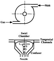
In internal mixing atomization (for example centrifugal-pneu- matic atomization),[159] the liquid metal and gas enter the swirl jet atomizer tangentially under pressure (Fig. 2.13).[159] The two fluids rotate, form a mixture, and accelerate in the confuser. Due to the strong centrifugal force, the liquid metal forms a film at the nozzle exit even without the presence of the gas. With the applied gas, the liquid film is atomized into a fine dispersion of droplets outside the nozzle.
82 Science and Engineering of Droplets
zation can be subsonic or supersonic, depending on the gas pressure and the gas nozzle geometry and configuration applied. High-pres- sure gas atomization with supersonic close-coupled atomizers is emerging as an efficient production method for high yields of fine powders.
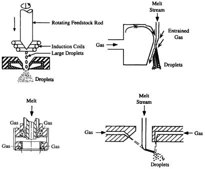
Figure 2.14. Schematic of a free-fall atomizer for atomization of melts.
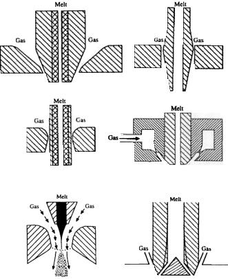
Figure 2.15. Schematic of a close-coupled atomizer for atomization of melts.
Droplet Generation 83
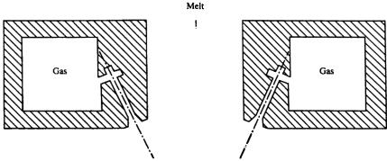
The close-coupled atomizer configuration has many variations (Fig. 2.16), such as the atomizers for high pressure gas atomization (HPGA),[160]-[162] SIGMA,[163][164] Ünal atomizer,[165]-[169] truncated plug atomizer,[170] NANOVAL atomizer,[171] annularized sheet atomizer, and ultrasonic gas atomizers.[154][172]-[174] The free-fall atomizer design may also have different geometry arrangements (Fig. 2.17). In some earlier designs, a single gas jet or multiple gas jets are arranged to horizontally impact a vertical, downward flowing metal stream. In most recent designs, multiple gas jets from discrete openings or a gas sheet jet from an annular nozzle form a converging cone concentric with the vertical metal stream. The atomized droplets solidify during flight downward in the chamber. To insure that all the droplet are completely solidified and cooled below certain temperature, the chamber must be sufficiently high (under certain conditions higher than 10 m) to prevent agglomeration by sintering at the base of the chamber. Thus, a vertical gas atomization facility may require a high building to house it. In this case, the horizontal gas atomization technique may be employed as an alternative. Due to the smaller dimension of a horizontal atomization facility with a typical chamber height of about 3 m, capital costs may be reduced. An additional solution may be filling the base of the chamber with water or liquid nitrogen to quench gas-atomized droplets for precious metals and tool steels. When water is used for quenching droplets, a subsequent powder drying process is then required similar to that in water atomization.
On average, current gas atomization processes have fairly low efficiency, perhaps 2–4%.[172] With expensive inert gases (for example, argon), production costs are high. The higher the gas velocity, the finer the powder size and the higher the yield of fine powders. To achieve the maximum efficiency in gas atomization and the maximum energy utilization of atomization gas, a laminar flow within the high velocity core of a gas jet is thus desired.[172] In other words, for the maximum efficiency, a liquid stream should be impacted by the gas at a maximum velocity, i.e., within a minimum distance for the gas flow from the gas nozzle to reach the metal stream, because the gas velocity and kinetic energy decay rapidly
86 Science and Engineering of Droplets
corresponding to a melt stream diameter of 2 to 15 mm. The flow rates for low melting-temperature metals range from 8 to 33 kg/min during continuous atomization operation. In commercial gas atomization processes, gas pressure is usually in the range of 0.5 to 9 MPa, corresponding to a gas flow rate between 0.02 and 0.24 m3/s. Higher gas pressures, up to 18 MPa, in conjunction with close-coupled atomizer designs have been examined. The high-pressure gas atomization has been demonstrated to be able to generate fine droplets of mass median size below 10 µm. Gas velocity distribution depends on nozzle geometry and configuration, and may vary from several tens to hundreds meter per second. Melt superheat is normally between 75 and 150°C. The representative mass median particle size is within the range of 50 to 300 µm with a standard deviation of about 2. The cooling rates of gas-atomized droplets are lower than those of wateratomized droplets for a given droplet size.
Table 2.12. Geometry Parameters in Gas Atomization of Melts
|
Parameter |
|
Value/Range |
|
|
Nozzle Number |
1, 2, 4, 12, 16, 18, 20, 24, or Annulus |
||
|
Nozzle Diameter (mm) |
0.25, 0.5, 0.7, 0.8, 1, 3 |
||
|
Relative Angle between Gas |
7–45 (Vertical) |
||
|
Nozzle and Metal Delivery |
|||
|
90 (Horizontal) |
|||
|
Nozzle (°) |
|||
|
|
|
||
|
|
External Mixing: |
||
|
|
Close-Coupled: |
SIGMA |
|
|
|
|
HPGA |
|
|
|
|
USGA |
|
|
|
|
Ünal |
|
Gas |
Configuration |
|
Truncated Plug |
|
Atomizer |
|
Annularized Sheet |
||
|
|
|||
|
|
|
NANOVAL |
|
|
|
Free-Fall: |
Horizontal |
|
|
|
|
Osprey |
|
|
|
|
Ultrasonic |
|
|
|
Internal Mixing: Centrifugal-pneumatic |
||
|
|
|
Straight |
|
|
Type of Nozzle |
|
Converging |
|
|
Converging-Diverging (Laval) |
|||
|
|
|||
|
|
Shock Wave (Ultrasonic) |
||
Metal |
Diameter (mm) |
|
1−15 |
|
Delivery |
Configuration |
|
Column |
|
Nozzle |
Annularized Sheet |
|||
|
||||
|
|
|
Droplet Generation 87 |
|
Table 2.13 Process Parameters in Gas Atomization of Melts |
||||
|
|
|
|
|
|
|
Parameter |
Value/Range |
|
|
Atomization |
Pressure (MPa) |
0.5–9 (1.4–8.2 in USGA) |
|
|
Gas |
Flow Rate (m3/s) |
0.02–0.24 |
|
|
Metal/ |
Superheat (°C) |
75–150 |
|
|
Alloy |
Flow Rate (kg/min) |
1–70 (2.4–4.8 in USGA) |
|
|
|
Material |
Ceramics/Refractory |
|
|
Melting |
|
Induction |
|
|
|
Resistance |
|
|
|
Crucible |
Heating/Melting Method |
|
|
|
Fuel Firing |
|
||
|
(Tundish) |
|
|
|
|
|
Electroslag Remelting |
|
|
|
|
|
|
|
|
Delivery |
Material |
Ceramics/Refractory |
|
|
Nozzle |
Steels |
|
|
|
|
|
||
|
Spray |
Pressure |
Atmosphere or |
|
|
Chamber |
Subatmosphere |
|
|
|
|
|
||
The relative angle between gas nozzle and metal delivery nozzle is an important factor influencing gas atomization. For an annular gas nozzle concentric with metal stream, too flat gas jets (large impingement angle) may cause a wide spray cone and a high back pressure against the metal stream. On the contrary, too steep gas jets (small impingement angle) may require a long distance for the gas flow from the gas nozzle to reach the metal stream, leading to the development of turbulence and poor gas efficiency. The impingement angle may vary from 15° to 80°, depending on the metal and atomization gas used.
Scale-up of gas atomizers is difficult and it requires the use of higher gas-to-melt mass flow rate ratio to maintain the same droplet size. The scale-up may also cause some complex phenomena to occur, such as the disappearance of the prefilming effect in closecoupled atomizers, the generation of turbulence in melt flow within delivery nozzle, and change in atomization mechanisms.
For the delivery of the atomization gas, different types of nozzles have been employed, such as straight, converging, convergingdiverging, and ultrasonic nozzles. A straight tube nozzle is used in subsonic gas atomization, while converging and converging-diverging
Droplet Generation 89
melting-temperature alloys, such as stainless steels, Niand Co-base alloys, pure Co, Ni, and Fe. The important geometry parameters and process parameters in USGA are the same as those for conventional gas atomization with closed-coupled atomizer configuration.[177] These include metal delivery nozzle diameter, relative angle between gas nozzle and metal delivery nozzle, axial and radial distances between gas nozzle and metal delivery nozzle, melt superheat, and gas pressure. Argon and nitrogen have been used as atomization gas with a pressure up to 8.2 MPa. Liquid stream diameter is typically 1 to 5 mm, and mass flow rate is about 2.4–4.8 kg/min, depending on metal density, stream diameter, and overpressure. The throughput is limited by the metal stream diameter. Increasing the metal stream diameter can enhance the metal flow rate but the energy available for the atomization may be severely attenuated when the stream diameter is beyond about 5 mm. The upper limit of the flow rate is about 15 kg/min for an annular USGA atomizer. To overcome this limitation, a linear USGA atomizer has been developed.[178] In the linear USGA atomizer, the liquid metal stream has a rectangular cross-section with a high aspect ratio, and the atomization gas is issued from a rectangular slit nozzle surrounding the vertical, downward flowing metal stream. Increasing the longitudinal dimension of the atomizer can enhance the flow rate, while reducing the transverse dimension can minimize the attenuation of the pulsed gas energy with an attendant pre-filming effect.
Ultrasonic gas atomization has several inherent advantages, including high relative velocities between gas and liquid metal phases, very fine spherical droplets with smooth surfaces and few satellites, and enhanced gas cooling capability due to the expansion of the high pressure gas. As a result of these features, cooling rates of droplets are high and droplets solidify within a short time, so that the atomization chamber (or container) can be small. The height and diameter of the spray chamber in laboratory scale may be as small as 1.7 m and 1.3 m, respectively. The gas investment is low and the gas utilization efficiency is relatively high. The gas demand is roughly as low as 25% of that for subsonic gas atomization. In addition, due to