

The Physics of Coronory Blood Flow - M. Zamir
.pdf2.8 Mechanical Analogy |
67 |
ence of certain forces and conditions. Indeed, both situations are governed by the same laws of physics, and it should not be surprising that the analytical descriptions of their mechanics are analogous. What is di erent between the two situations, and what makes the analogy useful, stems from a di erence not in the governing laws but in the type of forces and conditions involved and in the corresponding variables used in the two cases.
Thus, in the classical mechanics of a solid object, the familiar mass- damper-spring system is used in which an applied force may be opposed by a spring resistance proportional to the displacement of the object, a damper (or dashpot) resistance proportional to the rate of change of displacement (or velocity), and to an inertial resistance proportional to the second rate of displacement (or acceleration) [139, 76]. While in fluid flow these forces and conditions are not present in the same form, they are present in equivalent forms which obey the same governing laws, hence the basis for the analogy. For example, in fluid flow the capacitance of a tube or a system of tubes plays the role of the spring in the classical mechanics system, the viscous resistance between fluid and the tube wall plays the role of the damper, and the inertia of the fluid plays the role of the inertia of the solid object. These properties have already been discussed in earlier sections, what is required in this section is only to show how they translate into the properties of the classical mechanics system. The translation is not a direct one because the basic variables used in the classical mechanics system, namely mass, displacement and rates of displacement, are not readily available or convenient to work with in the fluid flow system.
Before we carry out this translation it is important to point out that the mechanical analogy has been used extensively in the modelling of coronary blood flow because the classical mechanics of a solid object are familiar and well understood. A model that can be expressed in terms of these mechanics, therefore, has the prospect of unveiling the unknown properties of the coronary circulation in terms which are familiar and well understood. In other words, the analogy is useful because the properties and behaviour of the mechanical system are more familiar and its elements more easily identified than the properties and elements of the fluid system. A potential for error is entailed in this modelling process, however, not because of any inaccuracy in the analogy but because elements of the coronary circulation required for the application of this analogy are not as easily identified as they are in a single tube. Thus, at the core of this modelling process is the fundamental “lumped model” assumption already discussed in Section 2.2, namely that the properties of many millions of tube segments in the coronary circulation can be represented collectively by those of an “equivalent” single tube. While many modelling studies have focused on the likely values of these lumped properties [111, 49, 59, 40, 121, 32, 102, 33, 195, 107, 98, 97]– capacitance, resistance, and inertance– the greater potential for error remains in the underlying assumption that these lumped properties actually exist. In other words, the mechanical analogy provides a
68 2 Modelling Preliminaries
mechanical model of the coronary circulation only on the assumption that the elements being modelled actually exist in the coronary circulation.
Furthermore, the behaviour of the classical mechanics system depends on a clear relation between the mass, the spring, and the damper. This relation is not known in the coronary circulation and must therefore be assumed in any modelling process. The e ect of capacitance in the coronary circulation, for example, is produced by a change in the caliber, and hence the volume, of some coronary arteries, resulting in a change in the overall volume of the system [191, 51, 184, 110, 96, 97]. But at the same time this change in diameter also alters the resistance to flow in these vessels. The relation between these two e ects is not known. In the classical mechanics system, by contrast, the elements representing capacitance and resistance are entirely separate and have no e ect on each other. A related issue is the extent to which the basic elements of capacitance, resistance, and inertance are in series or in parallel in the coronary circulation. In the classical mechanics system this is known a priori, but not so in the coronary circulation. Some studies have attempted to deal with these issues by taking more than one lumped element of each type, that is, more than one resistance and more than one capacitance, for example, and by placing them in di erent combinations of series and parallel arrangements [24, 36, 91, 115].
Despite these di culties, the mechanical analogy is a useful tool in modelling the coronary circulation because the analogy itself, as it applies to each individual element, is clearly valid. Thus, the relation between the flow rate q and pressure drop Δp in a tube, derived in Section 2.5 (Eq. 2.5.1), namely
Δp = L |
dq |
(2.8.1) |
|
dt |
|||
|
|
where L is the inertance, or inertial constant, of a bolus of fluid within the tube (Eq. 2.5.5), was shown in that section to be equivalent to the basic law of motion
F = m |
du |
(2.8.2) |
|
dt |
|||
|
|
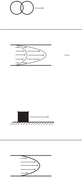
where m is the mass of a solid object in motion,u is its velocity, and F is the force acting on it. The analogy between the two equations is apparent and the correspondence between the two situations is illustrated in Fig. 2.8.1. The driving pressure di erence Δp in the fluid flow system corresponds to the acting force F in the classical mechanics system, while the inertance L corresponds to the mass m, and the flow rate q corresponds to the velocity u. In both cases the underlying law is “force equals mass times acceleration”.
Similarly, the viscous resistance to flow in a tube, discussed in Section 2.4, and the resulting relation between the pressure di erence Δp and the flow rate q, namely (Eq. 2.4.3)
Δp = Rq |
(2.8.3) |
2.8 Mechanical Analogy |
69 |
m m |
du |
F=m dt |
dq p=L dt
Fig. 2.8.1. The mechanical analogy between flow in a tube (bottom) and the motion of a solid object in classical mechanics (top). The driving pressure di erence Δp in the fluid flow system corresponds to the acting force F in the classical mechanics system, while the inertance L corresponds to the mass m, and the flow rate q corresponds to the velocity u. In both cases the underlying law is “force equals mass times acceleration”.
F=fu
p=Rq
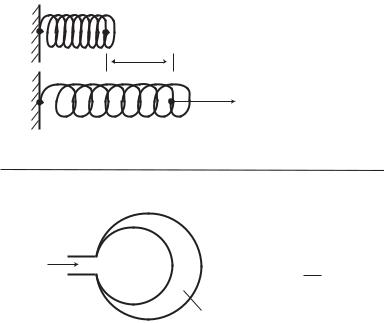
Fig. 2.8.2. Mechanical analogy between the viscous friction at the interface between fluid and tube wall, represented by velocity gradient at the tube wall (bottom), and the friction law in classical mechanics at the interface between two solid objects (top). Here the pressure di erence Δp in the tube corresponds to the driving force F in the classical mechanics system, the flow rate q corresponds to the friction velocity u, and the viscous resistance R corresponds to the friction coe cient f .
70 2 Modelling Preliminaries
where R is the resistance to flow due to viscosity (Eq. 2.4.4), is analogous to the classical law of friction at a solid-solid interface
F = f u |
(2.8.4) |
where f is the coe cient of friction at the interface, u is the relative velocity between the two surfaces, and F is the driving force. Again, the analogy between the two equations is apparent, and the two situations are illustrated in Fig. 2.8.2. Here the pressure di erence Δp corresponds to the driving force F and the flow rate q corresponds to the velocity u, as before, and the viscous resistance R corresponds to the friction coe cient f .
Finally, the capacitance of an elastic tube, discussed in Section 2.6, and the resulting relation between the pressure di erence Δp and the change in volume Δv, namely (Eqs. 2.6.4, 6)
(Δp) = |
|
1 |
Δv |
(2.8.5) |
|
C |
|||||
|
|
|
|||
x
F=k x
F
q |
v |
1 |
v |
|
p= |
||
|
|
C |
|
v
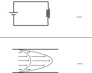
Fig. 2.8.3. Mechanical analogy: between the capacitance e ect of flow in an elastic tube, here represented by a balloon, and the stretch of a spring according to Hooke’s law. The pressure di erence Δp in the flow system corresponds to the applied force F in the spring system, the change in volume Δv of the tube/balloon corresponds to the change in length Δx of the spring, and 1/C in the flow system corresponds to the spring constant k, where C is a measure of the compliance of the tube/balloon, as defined by Eq. 2.6.4.
|
|
|
|
|
2.9 Electrical Analogy |
71 |
|
= |
1 |
|
qdt; |
Δv = |
qdt |
(2.8.6) |
|
|
|
||||||
C |
|||||||
where C is the capacitance of the tube, is analogous to the classical Hooke’s law for an elastic spring, namely
F = kΔx |
Δx = |
|
(2.8.7) |
|
= k |
udt; |
udt |
(2.8.8) |
|
where k is the spring constant, Δx is the spring extension, and F is the applied force. In the integral terms above, the spring extension is expressed in terms of the velocity u with which the spring is being extended, and the change in volume Δv of the elastic tube/balloon is expressed in terms of the flow rate q. The analogy between the two equations is apparent, with Δp corresponding to the applied force F as before, the change in volume Δv in the flow system corresponding to the change in length Δx of the spring, and 1/C in the flow system corresponding to the spring constant k. In the integral terms the flow rate q is seen to correspond to the velocity u in the mechanical system, as in Eqs. 2.8.1, 2. The analogy between the two situations is illustrated in Fig. 2.8.3.
2.9 Electrical Analogy
The dynamics of the coronary circulation can also be modelled, by analogy, in terms of an electric circuit with the basic elements of resistance, capacitance, and inductance. This analogy is subject to the same limitations as the mechanical analogy discussed in the previous section, namely the assumption that these elements can be identified with lumped properties of the coronary circulation. Nevertheless, electrical analogies have been used extensively in the study of the coronary circulation [24, 36, 91, 115] because electric circuits are much easier to manipulate, both analytically and experimentally, and are thus a convenient modelling tool. A model of the coronary circulation based on the electrical analogy can actually be built and tested experimentally. This feature of the electrical model makes it particularly useful in the study of pulsatile flow.
In the electrical analogy the electric potential, or voltage, V corresponds to the pressure di erence Δp in the flow system, and the electric current I along a conductor corresponds to the flow rate q along a tube. The basis of the analogy is that the relation between the voltage and current across an inductor L, namely [43]
V = L |
dI |
(2.9.1) |
|
dt |
|||
|
|
is analogous to the corresponding relation between the pressure di erence and flow rate in a tube, as in Eq. 2.8.1, where the inertia of the fluid produces
72 2 Modelling Preliminaries
V |
L |
dI |
|
|
V=L dt |
dq p=L dt
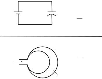
Fig. 2.9.1. Electrical analogy: between flow in a tube and the flow of current in an electric circuit, in the presence of inductance L in both systems. The driving pressure di erence Δp in the fluid flow system corresponds to the voltage V in the electrical system, and the flow rate q corresponds to the electric current I. Inductance in the fluid flow system is caused by a change in the flow rate, which is associated with acceleration or deceleration of a mass of fluid, while inductance in the electrical system is due to change in the current, which is associated with acceleration or deceleration of a mass of electrons.
an e ect analogous to that of an inductor, as discussed in Section 2.5. The analogy is illustrated in Fig. 2.9.1.
Similarly, the relation between the voltage and current across a resistor R,
namely [43] |
|
V = RI |
(2.9.2) |
is analogous to the relation between the pressure di erence and flow rate in a tube, as in Eq. 2.8.3, where viscous friction between fluid and the tube wall produces an e ect analogous to that of a resistor, as discussed in Section 2.4. The analogy is illustrated in Fig. 2.9.2.
Finally, the relation between the voltage across and current into a capacitor namely [43]
V = |
1 |
ΔQ |
|
|
(2.9.3) |
|
C |
|
|
||||
|
|
|
|
|
|
|
= |
1 |
|
Idt; |
ΔQ = |
Idt |
(2.9.4) |
|
||||||
C |
||||||
where C is the capacitance and ΔQ the accumulated electric charge on the capacitor, is analogous to the relation between the pressure di erence and flow rate into an elastic tube, as in Eqs.2.8.5,6. Here, because of the elasticity

2.9 Electrical Analogy |
73 |
V R
V=IR
p=Rq
Fig. 2.9.2. Electrical analogy: between flow in a tube and the flow of current in an electric circuit, in the presence of resistance R in both systems. The driving pressure di erence Δp in the fluid flow system corresponds to the voltage V in the electrical system, and the flow rate q corresponds to the electric current I. Resistance in the fluid flow system is due to loss of kinetic energy because of viscous friction between fluid and the tube wall, while that in the electrical system it results from a loss of electric energy within the resistor. Interestingly, in both cases the lost energy is converted to heat.
of the tube wall, the accumulated volume of fluid within the tube can change in analogy with a change in the electric charge accumulated on the capacitor. The analogy is illustrated in Fig. 2.9.3.
In summary, the electrical, mechanical, and fluid flow systems have three characteristics in common, namely inductance, resistance, and capacitance, and the dynamics of each system involves two principal variables, namely a driving force and consequent flow or motion. In the electrical system the three elements are an electric inductor, a resistor, and a capacitor, characterized respectively by their intrinsic constants L, R, C. The driving force is the voltage V , the motion is represented by the flow of electric current I, and the governing relations between these variables are:
inductance |
V = L |
dI |
|
(2.9.5) |
||
dt |
|
|||||
|
|
|
|
|
||
resistance |
V = RI |
|
(2.9.6) |
|||
|
1 |
|
|
|
|
|
capacitance |
V = |
|
Idt |
(2.9.7) |
||
C |
||||||
In the mechanical system the three elements are a moving object, a damper, and a spring, characterized respectively by the mass m of the moving object, the friction constant f of the damper, and the spring constant k. The driving
74 2 Modelling Preliminaries
V C
1
V= C Q
|
p= |
1 |
v |
q |
v |
C |
|
|
|
v
Fig. 2.9.3. Electrical analogy: between flow in a tube and the flow of current in an electric circuit, in the presence of capacitance C in both systems. The driving pressure di erence Δp in the fluid flow system corresponds to the voltage V in the electrical system, and the flow rate q corresponds to the electric current I. Capacitance in the fluid flow system is due to a change in the volume v of fluid within an elastic tube, here represented by an expandable balloon, while in the electrical system it is caused by a change in the total electric charge Q on a capacitor. The change in volume Δv in the fluid flow system is attained by a sustained flow rate into or out of the balloon, while the change in electric charge ΔQ on the capacitor is attained by a sustained current into or out of the capacitor.
force is an applied force F , the motion is represented by the velocity u of the moving object, and the governing relations between these variables are:
inductance |
F = m |
du |
|
(2.9.8) |
||
dt |
||||||
|
|
|
||||
resistance |
F = f u |
|
|
(2.9.9) |
||
capacitance |
F = k |
udt |
(2.9.10) |
|||
In the fluid flow system, finally, the three elements are the mass of fluid in a tube, viscous resistance between moving fluid and the tube wall, and capacitance produced by the elasticity of the tube wall, characterized respectively by their intrinsic constants L, R, C. The driving force is the pressure di erence Δp driving the flow, the motion is represented by the flow rate q, and the governing relations between these variables are:
inductance |
Δp = L |
dq |
(2.9.11) |
|
dt |
||||
|
|
|
|
|
|
|
|
|
2.10 Summary |
75 |
resistance |
Δp = Rq |
|
(2.9.12) |
||||
capacitance |
Δp = |
1 |
|
qdt |
(2.9.13) |
||
|
|
||||||
C |
|||||||
For flow in a tube of length l and radius a, assuming Poiseuille flow throughout, the resistance and inductance constants are respectively given by (Eqs. 2.4.4, and 2.5.5)
R = |
8μl |
; |
L = |
ρl |
|
(2.9.14) |
πa4 |
πa2 |
while the capacitance constant C is determined by the elasticity of the tube wall.
2.10 Summary
Modelling of the coronary circulation is necessary because experimental access to the dynamics of the system is severely limited. An understanding of the dynamics of coronary blood flow is important because in the absence of such understanding a purely static view of the system continues to be used in the clinical setting. In a static view of the system the primary concern is whether vessels are fully open or obstructed by disease. In a dynamic view the concern is more broadly based on all factors that may a ects the dynamics of the system, the patency of the conducting vessels being only one such factor.
In a lumped model of the coronary circulation the complex vasculature of the system is essentially replaced by an “equivalent” single tube with “lumped parameters” that are assumed to represent the system as a whole. The model is tested against any measurements that can be obtained from the coronary circulation, and parameter values are adjusted in search of agreement. Despite di culties associated with this concept, the lumped model has been an invaluable tool in the study of the coronary circulation by establishing some of its basic features.
The mechanics of flow in a tube is at the core of all lumped (as well as unlumped) model analysis. The analysis is usually based on the assumption of fully developed flow, ignoring flow in the entrance region of the tube where flow is in a developing phase. This assumption is fairly di cult to deal with because it is necessary, yet not easily justified.
Fluid viscosity together with the condition of no-slip at the tube wall produce “resistance” to steady flow in a tube. This resistance increases as the inverse of the tube radius to the fourth power, which means that if the radius of the tube is reduced by a factor of 2, the resistance to flow increases by a factor of 16. This dramatic relationship between vessel radius and resistance to flow figures heavily in clinical practice. It must be remembered, however, that coronary blood flow is not steady but pulsatile, where other forms of resistance exist.
76 2 Modelling Preliminaries
When fluid is accelerated or decelerated, fluid inertia gives rise to another form of resistance to flow, commonly referred to as inductance. The immediate e ect of inductance is to delay the response of the fluid to a change in the driving pressure di erence. The flow rate does not “match” the prevailing pressure di erence immediately but with a time delay. In that “transient state” the flow rate is attempting to reach a value appropriate for the prevailing pressure di erence, and it ultimately does if the prevailing pressure di erence does not change any further. But if the driving pressure di erence continues to change, as in oscillatory flow, the flow rate never reaches that appropriate value. It falls short and lags behind, more so at higher values of the inertial constant.
The “capacitance” of a tube or system of tubes arises when the tube wall is elastic (or possibly viscoelastic) and hence the volume of fluid contained within the tube or system of tubes can change. Capacitance is known to play a significant role in the dynamics of coronary blood flow but a definitive model of that role has yet to be formulated.
In addition to giving rise to capacitance, another fundamental consequence of elasticity of the tube wall is that of wave propagation. In an elastic tube, a change of pressure at one end of the tube does not reach the other end instantaneously as it does in a rigid tube. Instead, it stretches the elastic wall of the tube locally at first and then propagates down the tube like the crest of a wave on the surface of a lake. In pulsatile flow this wave propagation is continuous in space (along the tube) and in time. Inductance of the fluid and capacitance of the tube combine to form a new type of resistance, namely “resistance to wave propagation”, usually referred to as “reactance”, to be distinguished from “pure resistance” caused by viscous shear at the tube wall. Reactance and pure resistance combine to form the “impedance”, which plays a key role in “wave reflections”, all of which will be discussed more fully in later chapters.
Flow in an elastic tube is governed by the same physical laws and the same equations as the motion of a mass in a mass-damper-spring system. By this so-called “mechanical analogy”, inertia of the fluid in the fluid flow system is equivalent to the inertia of the mass in the mechanical system, viscous resistance in the fluid flow system is equivalent to resistance due to damper friction in the mechanical system, and capacitance of the tube in the fluid flow system is equivalent to the stretch of the spring in the mechanical system. The analogy is useful because the elements of the mechanical system are more familiar and their functions can be visualized more clearly than those in the fluid flow system.
Flow in an elastic tube is also analogous to the flow of current in an electric circuit. This so-called “electrical analogy” has been used widely in studying the dynamics of the coronary circulation and forms the basis and “language” of many lumped models of the system. Indeed, the terminology used for elements of resistance, inductance, and capacitance in the fluid flow system has been taken directly from these familiar elements in electrical systems, thus