

Radiation Physics for Medical Physiscists - E.B. Podgorsak
.pdf5.8 Range of Charged Particles |
159 |
5.8 Range of Charged Particles
In traversing matter charged particles lose their energy in ionizing and radiative collisions that may also result in significant deflections. In addition, charged particles su er a large number of deflections as a result of elastic scattering. These e ects are much more pronounced for light charged particles (electrons and positrons) in comparison to heavy charged particles.
•Heavy charged particles do not experience radiative losses, transfer only small amounts of energy in individual ionizing collisions with orbital electrons, and mainly su er small angle deflections in elastic collisions. Their path through an absorbing medium is thus essentially rectilinear, as shown schematically in Fig. 5.8.
•Electrons with kinetic energy EK, on the other hand, can lose energy up to EK/2 in individual ionizing collisions and energy up to EK in individual radiative collisions. Since they can also be scattered with very large scattering angles, their path through the absorbing medium is very tortuous, as shown schematically in Fig. 5.8.
Fig. 5.8. Schematic diagram of charged particle penetration into a medium. Top: Heavy charged particle; bottom: light charged particle (electron or positron)

160 5 Interactions of Charged Particles with Matter
•The range R of a charged particle in a particular absorbing medium is an experimental concept providing the thickness of an absorber that the particle can just penetrate. It depends on the particle’s kinetic energy, mass as well as charge, and on the composition of the absorbing medium. Various definitions of range that depend upon the method employed in the range determination are in common use.
•Generally, the concepts of range R must be distinguished from the concept of the path-length of a charged particle. This path-length simply provides the total path-length of the charged particle in the absorber and can be calculated, as suggested by Martin Berger and Stephen Seltzer in 1983, using the continuous slowing down approximation (CSDA) as follows:
|
EKi |
dE |
|
|
|
RCSDA = |
0 |
, |
(5.54) |
||
Stot(E) |
is the CSDA range (mean path-length) of the charged particle in the absorber,
is the initial kinetic energy of the charged particle,
is the total stopping power of the charged particle as a function of the kinetic energy EK.
• For heavy charged particles, RCSDA is a very good approximation to the
¯
average range R of the charged particle in the absorbing medium, because of the essentially rectilinear path of the charged particle (see Fig. 5.8) in the absorber.
•For light charged particles RCSDA is up to twice the range of charged particles in the absorber, because of the very tortuous path that the light charged particles experience in the absorbing medium (see Fig. 5.8).
5.9 Mean Stopping Power
In radiation dosimetry the main interest is in the energy absorbed per unit mass of the absorbing medium governed by collision losses of charged particles. It is often convenient to characterize a given radiation beam with electrons of only one energy rather than with an electron spectrum dφ/dE that is present in practice.
For example, monoenergetic electrons set in motion with an initial kinetic energy EKo in an absorbing medium will through their own slowing down process produce a spectrum of electrons in the medium ranging in energy from EKo down to zero. The electron spectrum dφ/dE, when ignoring any possible hard collisions, is given as
dφ(E) |
= |
N |
|
, |
(5.55) |
|
dE |
Stot(E) |
|||||
|
|
|
||||

5.10 Restricted Collision Stopping Power |
161 |
where
Nis the number of monoenergetic electrons of energy EKo produced per unit mass in the absorbing medium,
Stot(E) is the total stopping power.
For this electron spectrum, produced by monoenergetic electrons, we can
¯
define a mean collision stopping power Scol as follows:
|
|
EKo dφ Scol(E)dE |
|
|
|
|
|
0 |
dE |
|
|
|
|
|
|
|
|
Scol(EKo) = |
|
EKo dφ dE |
. |
(5.56) |
|
|
|
|
|
|
|
dE
0
Using (5.54) and (5.55) the integral in the denominator of (5.56) is determined as follows:
EKo |
dφ |
EKo |
dE |
|
|
|
0 |
0 |
|
(5.57) |
|||
|
dE = N |
|
= N RCSDA . |
|||
dE |
Stot(E) |
|||||
Using (5.50) and (5.55), the numerator of (5.56) is determined as follows:
EKo |
dE Scol(E)dE = N |
EKo |
Stot(E) dE |
|
|||
0 |
0 |
|
|||||
|
dφ |
|
|
Scol(E) |
|
|
|
|
|
|
EKo |
Stot(E) |
|
||
|
|
|
0 |
|
|||
|
|
= N |
|
Stot(E) − Srad(E) |
dE |
|
|
|
|
|
|
|
|||
|
|
= N EKo − N EKoB(EKo) . |
(5.58) |
||||
The mean collision stopping power Scol(EKi ) of (5.58) can now be written as
|
col(EKo) = EKo |
1 − B(EKo) |
. |
(5.59) |
S |
||||
|
|
RCSDA |
|
|
The relationship for Scol(EKo) above could also be stated intuitively by noting that an electron with an initial kinetic energy EKo will, through traveling the path-length equal to RCSDA, in the absorbing medium lose an energy EKoB(EKo) to bremsstrahlung and deposit an energy EKo[1 − B(EKo)] in the medium.
5.10 Restricted Collision Stopping Power
In radiation dosimetry one is interested in determining the energy transferred to a localized region of interest; however, the use of the mass collision stopping power Scol for this purpose may overestimate the dose because Scol incorporates both hard and soft collisions. The δ rays resulting from hard
162 5 Interactions of Charged Particles with Matter
collisions may be energetic enough to carry their kinetic energy a significant distance from the track of the primary particle thereby escaping from the region of interest. The concept of restricted mass collision stopping power L∆ has been introduced to address this issue by excluding the δ rays with energies exceeding a suitable threshold value ∆.
The choice of the energy threshold ∆ depends on the problem at hand. For dosimetric measurements involving air-filled ionization chambers with a typical electrode separation of 2 mm a frequently used threshold value is 10 keV (Note, the range of a 10 keV electron in air is of the order of 2 mm). For microdosimetric studies, on the other hand, one usually takes 100 eV as a reasonable threshold value.
Of course, to be physically relevant ∆ must not exceed ∆Emax, the maximum possible energy transfer to orbital electron from the incident particle with kinetic energy EK in a direct-hit collision. As shown in Sect. 4.3.2, ∆Emax equals to EK/2 for electrons, EK for positrons, and 2mec2β2/(1 − β2) for heavy charged particles [see (4.42), (4.41), and (4.39), respectively].
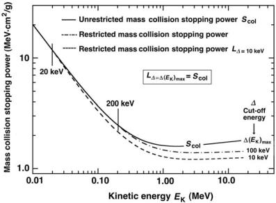
For a given kinetic energy EK of the primary particle the restricted collision stopping power L∆ is in general smaller than the unrestricted collision stopping power Scol; the smaller is ∆, the larger is the discrepancy. As ∆ increases from a very small value, the discrepancy diminishes until at ∆ = ∆Emax the restricted and unrestricted collision stopping powers become equal, i.e., L∆=∆Emax = Scol, irrespective of EK.
Figure 5.9 displays the unrestricted collision mass stopping power as well as the restricted collision mass stopping powers with ∆ = 10 keV and ∆ = 100 keV against kinetic energy EK for electrons in carbon based on data in the ICRU Report 37.
The following observations can now be made:
1.Since energy transfers to secondary electrons are limited to EK/2, the unrestricted and restricted mass stopping powers are identical for kinetic energies lower than or equal to 2∆. This is indicated in Fig. 5.9 with vertical lines at 20 keV and 200 keV for the threshold values ∆ = 10 keV and ∆ = 100 keV, respectively.
2.For a given EK > 2∆, the smaller is ∆, the larger is the discrepancy between the unrestricted and restricted stopping powers.
3.For a given ∆ and EK > 2∆, the larger is EK, the larger is the discrepancy between the unrestricted and restricted stopping powers.
5.11 Bremsstrahlung Targets
Bremsstrahlung production is of great importance in radiation oncology physics, since most of the radiation beams used for external beam radiotherapy are produced through bremsstrahlung interactions of monoenergetic electrons with solid targets. These targets are components of x-ray machines
5.11 Bremsstrahlung Targets |
163 |
Fig. 5.9. Unrestricted and restricted (∆ = 10 keV and ∆ = 100 keV) collision mass stopping powers for electrons in carbon against kinetic energy. Data are based on the ICRU Report 37
and linear accelerators; the most commonly used radiation-emitting machines for diagnosis and treatment of disease.
An electron that strikes the target with a given kinetic energy will undergo several di erent interactions with target atoms before it comes to rest and dissipates all of its kinetic energy in the target. As discussed in Sect. 5.1, there are two classes of electron interactions with a target atom:
1.with orbital electrons of the target atoms
2.with nuclei of the target atoms
Incident electron interaction with orbital electron of a target atom results mainly in collision loss and ionization of the target atom that may be accompanied by an energetic electron referred to as a delta ray. The collision loss will be followed by emission of characteristic x rays and Auger electrons.
Incident electron interaction with the nucleus of a target atom results mainly in elastic scattering events but may also result in radiative loss accompanied with bremsstrahlung production.
While bremsstrahlung is the major contributor to the x-ray spectrum at superficial and orthovoltage energies, it is essentially the sole contributor to the x-ray spectrum at megavoltage energies.
With regard to their thickness compared to the range of electrons in the target material, x-ray targets are either thin or thick. As discussed in
164 5 Interactions of Charged Particles with Matter
Sect. 3.2.8, the peak x-ray intensity occurs at a characteristic angle θmax that depends on the kinetic energy of the incident electrons:
1.In the diagnostic energy range (50 kVp to 120 kVp) θmax is 90o.
2.In the megavoltage radiotherapy range θmax is 0o and the target is referred to as a transmission target.
5.11.1 Thin X-ray Targets
Thin x-ray targets are mainly of theoretical interest and their thickness is very small compared to the range of electrons of given kinetic energy in the target material. By definition, a thin target is so thin that electrons:
1.Lose no energy by atomic ionizations
2.Su er no significant elastic collisions
3.Experience only one bremsstrahlung interaction while traversing the target.
The radiation emitted by accelerated or decelerated electrons of kinetic energy EK has an intensity I [(energy per photon) × (number of photons)] that is constant for all photon energies and experiences a sharp cut-o at hνmax = EK (Duane-Hunt law).
The shape of the spectral distribution of a thin x-ray target is independent of the target atomic number Z.
5.11.2 Thick X-ray Targets
Thick x-ray targets have thicknesses of the order of the range of electrons R in the target material. In practice, typical thicknesses are equal to about 1.1 R to satisfy two opposing conditions:
1.To ensure that no electrons that strike the target can traverse the target
2.To minimize the attenuation of the bremsstrahlung beam in the target.
Thick target radiation is much more di cult to handle theoretically than thin target radiation; however, in practice most targets used in bremsstrahlung production are of the thick target variety. Main characteristics of thick target radiation are as follows:
•The spectral distribution of thick-target bremsstrahlung is essentially a super-position of contributions from a large number of thin targets, each thin target traversed by a lower energy monoenergetic electron beam having a lower hνmax.
•The integrated intensity of thick-target bremsstrahlung depends linearly on the atomic number Z of the target material. This implies that high Z targets will be more e cient for x-ray production that low Z targets.

5.11 Bremsstrahlung Targets |
165 |
•In megavoltage radiotherapy only photons in the narrow cone in the forward direction are used for the clinical beams and the x-ray yield in the forward direction is essentially independent of the atomic number Z of the target.
•The average energy Erad radiated by an electron of initial energy EKo in being stopped in a thick target was given in (5.50) as
|
EKo |
Srad(E) |
|
|
Erad = EKo B(EKo) = |
0 |
(5.60) |
||
Stot(E) dE |
•In the diagnostic energy range, where EKo mec2, the mass radiative stopping power Srad is independent of the kinetic energy of the electron and, from (5.3) combined with Table 5.1, given as
Srad = (NA/A)σradEKo = (16/3)α re2Z2EKo
= (16/3)α r2 |
(N |
A |
/A)Z2 |
(E |
Ko |
+ m |
c2). |
(5.61) |
e |
|
|
|
e |
|
|
•For EKo mec2 the mass radiative stopping power Srad of (5.61) is independent of the kinetic energy of the electron and may then be simplified to read
Erad = Srad |
EKo |
Stot(E) |
|
|||
0 |
|
|||||
|
|
dE |
|
|
||
= SradRCSDA = const |
NA |
Z2RCSDA . |
(5.62) |
|||
|
||||||
|
|
|
|
A |
|
|
•Since in this energy range Stot ≈ Scol and Scol NAZ/A, we note that RCSDA (NAZ/A)−1 and the average energy radiated by the electron stopped in a thick target is linearly proportional to the atomic number Z of the target, i.e.,
Erad Z f (EKi , Z) , |
(5.63) |
where f (EKi , Z) is a slowly varying function of Z.
•The thick target bremsstrahlung is linearly proportional to the atomic number of the target in the diagnostic energy range where EKo mec2. This rule will fail when EKo becomes large enough for the radiative losses to no longer be negligible in comparison with collision losses.
5.11.3 Practical Aspects of Megavoltage X-ray Targets
Traditionally, the requirements for target properties, established during the early days of x-ray technology, were quite straightforward:
1.High atomic number Z to maximize e ciency for x-ray production.
2.High melting point to minimize damage to the target from the electron beam.
166 5 Interactions of Charged Particles with Matter
Tungsten satisfies both conditions and is thus the material of choice in most x-ray tubes. With the advent of megavoltage linear accelerators (linacs), it seemed prudent to adopt tungsten as the target material in linacs. The approach worked well for linac energies below 15 MV; however, at energies above 15 MV high Z targets did not prove optimal. This was established in the early 1970s with 25 MV linacs that incorporated tungsten target/tungsten flattening filter combinations. A flattening filter is an important component of the clinical x-ray beam forming assembly in linacs and betatrons, producing a flat, clinically useful megavoltage photon beam.
The tungsten target/tungsten flattening filter combination in the 25 MV linac produced an x-ray beam with tissue-penetrating properties that matched betatron beams that were operated at 16 MV. This was a significant energy di erence considering the extra cost in building a linac running at 25 MV rather than at 16 MV.
The cause of the discrepancy between the linac beam and the betatron beam was traced to the target/flattening filter design and atomic number in the two machines. By virtue of its design, the betatron uses a thin target that inherently produces a more penetrating photon beam in comparison to linac’s thick transmission target. It also used an aluminum flattening filter in comparison to linac’s tungsten filter, and aluminum with its low atomic number will soften the megavoltage x-ray beam less than the high atomic number target.
A thin target may be used in betatrons because the target is immersed in a strong magnetic field that engulfs the doughnut and sweeps the transmitted electrons into the doughnut wall before they can strike the flattening filter and produce unwanted o -focus x-rays. In linacs the targets are not immersed in a strong magnetic field so they are of the thick variety to prevent any electrons from traversing the target.
The 25 MV linac beam was thus formed with a thick high Z target and a high Z flattening filter, while the betatron beam was formed with a thin target and a low Z flattening filter. A study of unfiltered linac x-ray beams has shown that a low Z thick target produces the same quality x-ray beam as a thin betatron target at beam energies above 15 MeV. Thus, a conclusion can be made that x-ray targets in this energy range should be made of low atomic number materials to produce the most penetrating photon beams.
•The low Z target recommendation goes against the target high Z requirement for maximizing the x-ray production; however, it turns out that in the megavoltage energy range the x-ray production in the forward direction is actually independent of target atomic number and for practical radiotherapy one uses only photons projected in the forward direction.
•Even though the x-ray yield depends on Z of the target (the higher is Z, the higher is the yield), this yield is stated for the 4π geometry and in radiotherapy one uses only the forward direction for which the yield is essentially independent of Z. It is actually advantageous to have a lower
5.11 Bremsstrahlung Targets |
167 |
x-ray yield in regions outside the useful radiotherapy beam, because this lowers the required shielding against leakage radiation produced by the linac.
•The traditional target requirement on a high melting point is not as stringent for high-energy linacs in comparison with diagnostic x-ray tubes. At high photon energies used in radiotherapy, the e ciency for x-ray production is of the order of 10% to 20% rather than below 1% as is the case with diagnostic x-ray tubes. Therefore, the electron beam energy deposition and target cooling are of much less concern in megavoltage linacs as compared to diagnostic range x-ray tubes.
•Since for the same electron kinetic energy (above 15 MeV) the e ective energy of the radiation beam in the forward direction is actually larger for low Z targets in comparison with high Z targets, a conclusion can be made that low atomic number targets should be used in high-energy linear accelerators. The practical problem with this stipulation unfortunately is that it is di cult to find a low Z target that also has a high density (i.e., has a relatively short range of electrons) to make it compact for use in
linacs. For example, the required target thickness for 25 MeV electrons is 1 cm of lead (Z = 82, ρ = 11.3 g/cm−3), 0.5 cm of tungsten (Z = 74, ρ = 19.25 g/cm−3), and 4 cm of aluminum (Z = 13, ρ = 2.7 g/cm−3). From the atomic number point of view aluminum is an excellent choice of target material, however, its low density precludes its use as a practical target material in high-energy linear accelerators.
•As far as flattening filters are concerned, low atomic number materials are preferable in the range above 15 MV because they cause less beam softening than high atomic number materials; however, similarly to the situation with target materials, space constraints in linac heads limit the practical choices available. Thus, aluminum was a good choice for flattening the betatron beam, since the field size produced by the machine was limited to a 20 × 20 cm2 field. Modern linear accelerators, however, must deliver fields up to 40 × 40 cm2 at 100 cm from the target and these field sizes cannot be supported by aluminum flattening filters because of the associated required large size of the filter.
•The mass angular scattering power that depends linearly on the atomic number of the flattening filter material, as discussed in Sect. 4.5, also must be considered when the choice of flattening filter material is made.
ˇ
Cerenkov Radiation in a Nuclear Reactor
ˇ
The photograph on the next page shows Cerenkov blue radiation from the reactor core during operation of a TRIGA Mark II nuclear reactor at Kansas State University (KSU) in Manhattan, Kansas.
The KSU reactor, in operation since 1962, is a swimming pool reactor, so called because it sits near the bottom of a large concrete pool of water. Currently licensed to operate at 250 kW thermal power, it serves as an excellent tool for nuclear research, education and training. It also provides special services, such as nucleosynthesis, neutron activation analysis, neutron radiography and material irradiation.
Nuclear reactors are based on fission chain reactions that are self-sustained by using some of the fission-produced neutrons to induce new fissions. Each fission event liberates energy of the order of 200 MeV that is distributed among the fission fragments, fission neutrons, beta particles from the beta decay of radioactive fission fragments, and gamma rays.
The important components of a reactor core are: reactor fuel, most commonly uranium-235; moderator that slows down to thermal energies the fission-produced fast neutrons; and control rods that very e ciently absorb neutrons. The position of the control rods in the reactor core a ects the number of neutrons available to induce fission thereby controlling the fission rate, reactor power, and reactor shut down.
While no particle can exceed the speed of light in vacuum, in a given medium it is quite possible for charged particles to propagate with velocities that are larger than the speed of light in that medium. When a nuclear reactor is in operation, many fission products emit high-energy beta particles (electrons and positrons) and these particles may travel in water surrounding the reactor core at velocities larger than the speed of light in water. Water molecules line up along the path of beta particles, and, as they return to their normal random orientations, energy is released in the form of visible and ultraviolet photons. This type of radiation, produced only when a particle moves faster than speed of light in medium, is called
ˇ
Cerenkov radiation and is named after the Russian scientist who in 1934 was the first to study the phenomenon in depth.
Unlike fluorescence and atomic emission spectra that have characteristic spec-
ˇ
tral peaks, Cerenkov radiation is continuous and its intensity is proportional to the frequency (inversely proportional to wavelength), resulting in the predominantly blue emission visible to the naked eye and even more emission in the ultraviolet
ˇ
region of the photon spectrum, invisible to the human eye. The Cerenkov e ect is analogous to the sonic boom in acoustics when an object exceeds the speed of sound in air.
Photograph: Courtesy of Kansas State University, TRIGA Mark II Nuclear Reactor, Reproduced with Permission.