Radiation Physics for Medical Physiscists - E.B. Podgorsak
.pdf
3.6 Particle Accelerators |
109 |
Fig. 3.9. Schematic diagram of a cyclotron. left: vertical cross section, right: top view
•A radiofrequency voltage with a constant frequency between 10 and 30 MHz is applied between the two electrodes and the charged particle is accelerated while crossing the gap between the two electrodes.
•Inside the electrodes there is no electric field and the particle drifts under the influence of the magnetic field in a semicircular orbit with a constant speed, until it crosses the gap again. If, in the meantime, the electric field has reversed its direction, the particle will again be accelerated across the gap, gain a small amount of energy, and drift in the other electrode along a semicircle of a larger radius than the former one, resulting in a spiral orbit and a gradual increase in kinetic energy after a large number of gap crossings.
3.6.3 Microtron
The microtron is an electron accelerator, which combines the features of a linac and a cyclotron. The concept of the microtron was developed by Vladimir I. Veksler in 1944 and the machine is used in modern radiotherapy, albeit to a much smaller extent than are linacs.
Two types of microtrons were developed: circular and racetrack.
•In the circular microtron the electron gains energy from a microwave resonant cavity and describes circular orbits of increasing radius in a uniform magnetic field. To keep the particle in phase with the microwave power, the cavity voltage, frequency, and magnetic field are adjusted in such a way that after each passage through the cavity, the electrons gain an energy increment resulting in an increase in the transit time in the magnetic field equal to an integral number of microwave cycles.
•In the racetrack microtron the magnet is split into two D-shaped pole pieces that are separated to provide greater flexibility in achieving e cient electron injection and higher energy gain per orbit through the use of multi-cavity accelerating structures similar to those used in linacs. The electon orbits consist of two semicircular and two straight sections.
110 3 Production of X Rays
3.7 Linear Accelerator
During the past few decades medical linear accelerators (linacs) have become the predominant machine in treatment of cancer with ionizing radiation. In contrast to linacs used for high-energy physics research, medical linacs are compact machines mounted isocentrically so as to allow practical radiation treatment aiming the beam toward the patient from various directions.
Medical linacs are cyclic accelerators which accelerate electrons to kinetic energies from 4 MeV to 25 MeV using non-conservative microwave radiofrequency (RF) fields in the frequency range from 103 MHz (L band) to 104 MHz (X band), with the vast majority running at 2856 MHz (S band).
In a linear accelerator the electrons are accelerated following straight trajectories in special evacuated structures called accelerating waveguides. Electrons follow a linear path through the same, relatively low, potential di erence several times; hence, linacs also fall into the class of cyclic accelerators.
Various types of linacs are available for clinical use. Some provide x rays only in the low megavoltage range (4 MV or 6 MV), others provide both x rays and electrons at various megavoltage energies. A typical modern highenergy linac will provide two photon energies (e.g., 6 MV and 18 MV) and several electron energies (e.g., 6, 9, 12, 16, 22 MeV)
3.7.1 Linac Generations
During the past 40 years, medical linacs have gone through five distinct generations, making the contemporary machines extremely sophisticated in comparison with the machines of the 1960s. Each generation introduced the following new features:
•Low energy photons (4–8 MV):
straight-through beam; fixed flattening filter; external wedges; symmetric jaws; single transmission ionization chamber; isocentric mounting.
•Medium energy photons (10–15 MV) and electrons:
bent beam; movable target and flattening filter; scattering foils; dual transmission ionization chamber; electron cones.
•High energy photons (18–25 MV) and electrons:
dual photon energy and multiple electron energies; achromatic bending magnet; dual scattering foils or scanned electron pencil beam; motorized wedge; asymmetric or independent collimator jaws.
•High energy photons and electrons:
computer-controlled operation; dynamic wedge; electronic portal imaging device; multileaf collimator.
•High energy photons and electrons:
photon beam intensity modulation with multileaf collimator; full dynamic conformal dose delivery with intensity modulated beams produced with a multileaf collimator; on-board imaging for use in adaptive radiotherapy.

3.7 Linear Accelerator |
111 |
3.7.2 Components of Modern Linacs
The linacs are usually mounted isocentrically and the operational systems are distributed over five major and distinct sections of the machine:
1.gantry;
2.gantry stand or support;
3.modulator cabinet;
4.patient support assembly, i.e., treatment couch;
5.control console.
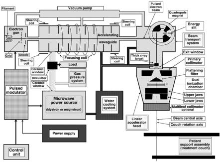
A schematic diagram of a typical modern S-band medical linac is shown in Fig. 3.10. Also shown are the connections and relationships among the various linac components, listed above. The diagram provides a general layout of linac components; however, there are significant variations from one commercial machine to another, depending on the final electron beam kinetic energy as well as on the particular design used by the manufacturer. The length of the accelerating waveguide depends on the final electron kinetic energy, and ranges from 30 cm at 4 MeV to 150 cm at 25 MeV.
The beam-forming components of medical linacs are usually grouped into six classes:
Fig. 3.10. Schematic diagram of a medical linear accelerator (linac)
112 3 Production of X Rays
1.injection system;
2.RF power generation system;
3.accelerating waveguide;
4.auxiliary system;
5.beam transport system; and
6.beam monitoring system and beam collimation.
The injection system is the source of electrons, essentially a simple electrostatic accelerator called an electron gun. Two types of electron gun are in use: diode type and triode type, both containing a heated cathode (at a negative potential of the order of −25 kV) and a perforated grounded anode. In addition, triode type gun also incorporates a grid placed between the cathode and the anode. Electrons are thermionically emitted from the heated cathode, focused into a pencil beam and accelerated toward the perforated anode through which they drift into the accelerating waveguide.
The radiofrequency (RF) power generating system produces the high power microwave radiation used for electron acceleration in the accelerating waveguide and consists of two components: the RF power source and the pulsed modulator. The RF power source is either a magnetron or a klystron in conjunction with a low power RF oscillator. Both devices use electron acceleration and deceleration in vacuum for production of the high power RF fields. The pulsed modulator produces the high voltage, high current, short duration pulses required by the RF power source and the electron injection system.
Electrons are accelerated in the accelerating waveguide by means of an energy transfer from the high power RF field which is setup in the accelerating waveguide and produced by the RF power generator. The accelerating waveguide is in principle obtained from a cylindrical uniform waveguide by adding a series of disks (irises) with circular holes at the center, positioned at equal intervals along the tube. These disks divide the waveguide into a series of cylindrical cavities that form the basic structure of the accelerating waveguide in a linac.
The auxiliary system of a linac consists of several basic systems that are not directly involved with electron acceleration, yet they make the acceleration possible and the linac viable for clinical operation. These systems are: the vacuum-pumping system, the water-cooling system, the air-pressure system, and the shielding against leakage radiation.
The electron beam transport system brings the pulsed high-energy electron beam from the accelerating waveguide onto the target in the x-ray therapy mode and onto the scattering foil in the electron therapy mode.
The beam monitoring and beam collimation system forms an essential system in a medical linac ensuring that radiation dose may be delivered to the patient as prescribed, with a high numerical and spatial accuracy.
3.7 Linear Accelerator |
113 |
3.7.3 Linac Treatment Head
The linac head contains several components, which influence the production, shaping, localizing, and monitoring of the clinical photon and electron beams. Electrons, originating in the electron gun, are accelerated in the accelerating waveguide to the desired kinetic energy and then brought, in the form of a pencil beam, through the beam transport system into the linac treatment head, where the clinical photon and electron beams are produced. The important components found in a typical head of a modern linac include:
1.several retractable x-ray targets;
2.flattening filters and electron scattering foils (also referred to as scattering filters);
3.primary and adjustable secondary collimators;
4.dual transmission ionization chambers;
5.field defining light and range finder ;
6.optional retractable wedges or full dynamic wedges;
7.multileaf collimator (MLC).
Clinical photon beams are produced in medical linear accelerators with a target/flattening filter combination. The electron beam accelerated to a given kinetic energy in the accelerating waveguide is brought by the beam transport system onto an x-ray target in which a small fraction (of the order of 10%) of the electron pencil beam kinetic energy is transformed into bremsstrahlung x rays. The intensity of the x ray beam produced in the target is mainly forward peaked and a flattening filter is used to flatten the beam and make it useful for clinical applications. Each clinical photon beam produced by a given electron kinetic energy has its own specific target/flattening filter combination.
Photon beam collimation in a typical modern medical linac is achieved with three collimation devices: the primary collimator, the secondary movable beam defining collimator, and the multileaf collimator (MLC). The primary collimator defines a maximum circular field which is further truncated with the adjustable rectangular collimator consisting of two upper and two lower independent jaws and producing rectangular or square fields with a maximum dimension of 40 × 40 cm2 at the linac isocenter, 100 cm from the x-ray target.
The MLCs are a relatively new addition to modern linac dose delivery technology. In principle, the idea behind an MLC is simple. It allows production of irregularly shaped radiation fields with accuracy and e ciency and is based on an array of narrow collimator leaf pairs, each leaf controlled with its own miniature motor. The building of a reliable MLC system presents a substantial technological challenge and current models incorporate up to 120 leaves (60 pairs) covering radiation fields up to 40 × 40 cm2 and requiring 120 individually computer-controlled motors and control circuits.
114 3 Production of X Rays
Clinical electron beams are produced in a medical linac by retracting the target and flattering filter from the electron pencil beam and either scattering the electron pencil beam with a scattering foil or deflecting and scanning the pencil beam magnetically to cover the field size required for electron beam treatment. Special cones (applicators) are used to collimate the clinical electron beams.
Dose monitoring systems in medical linacs are based on transmission ionization chambers permanently imbedded in the linac clinical photon and electron beams. The chambers are used to monitor the beam output (patient dose) continuously during the patient treatment. In addition to dose monitoring the chambers are also used for monitoring the radial and transverse flatness of the radiation beam as well as its symmetry and energy. For patient safety, the linac dosimetry system usually consists of two separately sealed ionization chambers with completely independent biasing power supplies and readout electrometers. If the primary chamber fails during patient treatment, the secondary chamber will terminate the irradiation, usually after an additional dose of only a few percent above the prescribed dose has been delivered.
3.7.4 Configuration of Modern Linacs
At megavoltage electron energies the bremsstrahlung photons produced in the x-ray target are mainly forward-peaked and the clinical photon beam is produced in the direction of the electron beam striking the target.
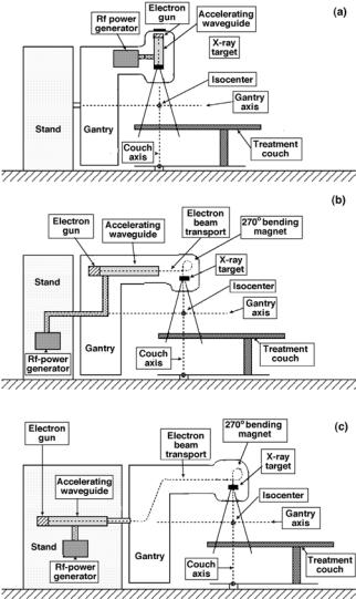
In the simplest and most practical configuration, the electron gun and the x-ray target form part of the accelerating waveguide and are aligned directly with the linac isocentre, obviating the need for a beam transport system. A straight-through photon beam is produced and the RF power source is also mounted in the gantry. The simplest linacs are isocentrically mounted 4 or 6 MV machines with the electron gun and target permanently built into the accelerating waveguide, thereby requiring no beam transport nor o ering an electron therapy option.
Accelerating waveguides for intermediate (8–15 MeV) and high (15– 30 MeV) electron energies are too long for direct isocentric mounting, so they are located either in the gantry, parallel to the gantry axis of rotation, or in the gantry stand. A beam transport system is then used to transport the electron beam from the accelerating waveguide to the x-ray target. The RF power source in the two configurations is commonly mounted in the gantry stand. Various design configurations for modern isocentric linear accelerators are shown in Fig. 3.11.

3.7 Linear Accelerator |
115 |
Fig. 3.11. Design configurations for isocentric medical linacs. a Straight-through beam design; the electron gun and target are permanently embedded into the accelerating waveguide; machine produces only x rays with energies of 4–6 MV; the rf-power generator is mounted in the gantry. b Accelerating waveguide is in the gantry parallel to the isocenter axis; electrons are brought to the movable target through a beam transport system; the rf-power generator is located in the gantry stand; machine can produce megavoltage x rays as well as electrons. c Accelerating waveguide and rf-power generator are located in the gantry stand; electrons are brought to the movable target through a beam transport system; machine can produce megavoltage x rays as well as electrons
An Electron Pencil Beam Penetrating into Water
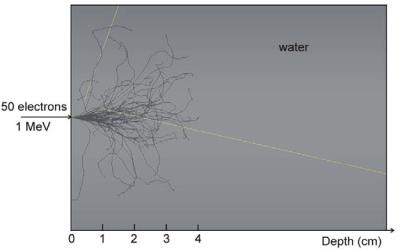
The photograph on the next page represents a 1 MeV electron pencil beam consisting of 50 electrons penetrating into a water phantom. The distribution is calculated with the EGS-nrc Monte Carlo code that traces the trajectories of the individual incident electrons through their various Coulomb interactions with the orbital electrons and nuclei of the water molecules.
Interactions of incident electrons with orbital electrons result in collision (ionization) losses of the incident electrons; interactions with nuclei result in scattering (change in direction of motion) and may also result in radiative (bremsstrahlung) losses. The jagged paths in the figure represent incident electron tracks in water; the two straight traces represent two bremsstrahlung photons, both escaping the phantom. A careful observer will also be able to discern the tracks of secondary electrons (δ electrons) that are liberated in water by the primary electrons and given su cient kinetic energies to be able to ionize matter in their own right.
Monte Carlo calculations are a statistical process and their accuracy depends on the number of events included in the calculation. The larger is this number, the better is the accuracy of the calculation and, of course, the longer is the calculation time. With the ever-increasing power and speed of computers, Monte Carlo techniques are becoming of practical importance in radiation dosimetry and in calculations of dose distributions in patients treated with x rays, gamma rays, or particle beams.
While the current treatment planning techniques are based on a set of measurements carried out in water phantoms, practical Monte Carlo-based treatment planning algorithms that are currently under development in many research centers will base the calculations directly on data for a particular patient, thereby, in principle, significantly improving the accuracy of dose distribution calculations.
Recently patient-specific Monte Carlo-based treatment planning systems have become commercially available; however, their routine implementation in radiotherapy clinics still hinges on many factors, such as adequate modeling of radiation sources; solving several experimental problems involving tissue inhomogeneities; answering many important clinical questions; updating the dose calculation algorithms; and improving the computing hardware. It is expected that in the near future incorporation of predictive biological models for tumor control and normal tissue complication into Monte Carlo-based dose calculation engines will form the standard approach to radiotherapy treatment planning.
Photograph: Courtesy of Jan P. Seuntjens, Ph.D., McGill University, Montr´eal. Reproduced with Permission.

4 Two-Particle Collisions
This chapter deals with two-particle collisions characterized by an energetic projectile striking a stationary target. Three categories of projectiles of interest in medical physics are considered: light charged particles such as electrons and positrons, heavy charged particles such as protons and α particles, and neutral particles such as neutrons. The targets are either atoms as a whole, atomic nuclei, or atomic orbital electrons. The collisions are classified into three categories: nuclear reactions; elastic collisions; and inelastic collisions.
The many types of interacting particles as well as the various possible categories of interactions result in a wide range of two-particle collisions of interest in medical physics. Several parameters, such as the Q value and energy threshold in nuclear reactions, and energy transfer, scattering angle and angular scattering power in elastic scattering, used in characterization of twoparticle collisions, are defined in this chapter. Many of these parameters play an important role in radiation dosimetry through their e ects on stopping powers, as discussed in Chap. 5. They also play an important role in the production of radioactive nuclides (nucleosynthesis), as discussed in Chap. 8.

118 4 Two-Particle Collisions
4.1 Collisions of Two Particles: General Aspects
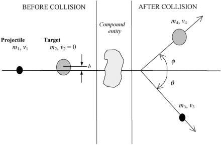
A common problem in nuclear physics and radiation dosimetry is the collision of two particles in which a projectile with mass m1, velocity υ1 and kinetic energy (EK)1 strikes a stationary target with mass m2 and velocity υ2 = 0.
As shown schematically in Fig. 4.1, the collision in the most general case results in an intermediate compound that decays into two reaction products: one of mass m3 ejected with velocity υ3 at an angle θ to the incident projectile direction, and the other of mass m4 ejected with velocity υ4 at an angle φ to the incident projectile direction.
The probability or cross section for a particular collision as well as the collision outcome depend on the physical properties of the projectile (mass, charge, velocity, kinetic energy) and the stationary target (mass, charge).
Projectiles of interest in medical physics fall into one of three categories, each category characterized by its own specific mechanism for the interaction between the projectile and the target. The three categories of projectiles are:
(i) heavy charged particles, (ii) light charged particles, and (iii) neutrons.
Fig. 4.1. Schematic representation of a two-particle collision of a projectile with mass m1, velocity υ1 and kinetic energy (EK)1 striking a stationary target with mass m2 and velocity υ2 = 0. An intermediate compound entity is produced temporarily that decays into two reaction products, one of mass m3 ejected with velocity υ3 at an angle θ to the incident projectile direction, and the other of mass m4 ejected with velocity v4 at an angle φ to the incident projectile direction
