Radiation Physics for Medical Physiscists - E.B. Podgorsak
.pdf
3.1 X-Ray Line Spectra (Characteristic Radiation) |
89 |
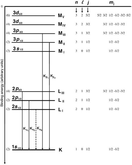
Fig. 3.1. Typical energy level diagram for a high atomic number element showing the K, L, and M shells with associated sub-shells. The numbers in brackets indicate the maximum possible number of electrons in a given sub-shell equal to (2j +1). Kα and Kβ transitions are also shown. The allowed Kα and Kβ transitions are shown with solid lines, the forbidden Kα3 transition is shown with a dashed line
90 3 Production of X Rays
The selection rules for allowed characteristic transitions are:
∆ = ±1 and ∆j = 0 or ± 1 , |
(3.1) |
with the proviso that transitions from j = 0 to j = 0 are forbidden.
•The energies released through an electronic transition are a ected by the atomic number Z of the absorbing atom and by the quantum numbers of the atomic shells involved in the electronic transition.
•Transitions between outer shell electrons may result in optical photons and are referred to as optical transitions (hν of the order of a few eV); transitions between inner shells of high atomic number elements may result in x rays and are referred to as x-ray transitions (hν of the order of 10 to 100 keV).
In general the following conventions are used in atomic physics:
1.Transitions to the K shell are referred to as the K lines, to the L shell as L lines, to the M shell as M lines, etc.
2.Transitions from the nearest neighbor shell are designated as α transitions, from the second nearest neighbor shell β transitions, etc.
3.Transitions from one shell to another do not all have the same energy because of the fine structure (sub-shells) in the shell levels. The highest energy transition between two shells is usually designated with number 1, second highest with number 2, etc.
4.In Fig. 3.1 the transition Kα3 represents a forbidden transition (∆ = 0) from the L to the K shell (2s1/2 → 1s1/2 with ∆ = 0 and ∆j = 0).
5.The transition Kβ1 represents an allowed transition from the M to the K shell (3p3/2 → 1s1/2 with ∆ = 1 and ∆j = 1).
3.1.2 Auger E ect and Fluorescent Yield
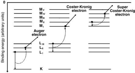
The allowed transitions between electronic shells or orbits do not necessarily result in characteristic x rays, they may also result in an Auger e ect. Electrons may undergo transitions that violate the selection rules applicable for production of characteristic radiation; however, the energy di erence is then transferred to other orbital electrons that are ejected from the atom as Auger electrons, Coster-Kronig electrons or super Coster-Kronig electrons, as shown schematically in Fig. 3.2. The kinetic energy of these electrons is equal to the energy released through the primary electronic transition less the binding energy of the ejected Auger electron. Emission of Auger electrons from an atom is referred to as the Auger e ect.
In Auger e ect the primary transition occurs between two shells, in the Coster-Kronig and super Coster-Kronig e ects the primary transition occurs within two sub-shells of a shell.
1.In the Coster-Kronig e ect the transition energy is transferred to an electron in another shell and the emitted electron is called a CosterKronig electron.

3.1 X-Ray Line Spectra (Characteristic Radiation) |
91 |
Fig. 3.2. Schematic representation of the Auger e ect, the Coster-Kronig e ect and the super Coster-Kronig e ect. In the Auger e ect the electron makes an intershell transition and the transition energy is transferred to the Auger electron. In the Coster-Kronig e ect the electron makes an intrashell transition and the transition energy is transferred to an electron in a higher shell. In the super Coster-Kronig e ect the electron makes an intrashell transition and the energy is transferred to an electron in the same shell
2.In the super Coster-Kronig e ect the energy is transferred to a sub-shell electron within the shell in which the primary transition occurred and the emitted electron is called a super Coster-Kronig electron.
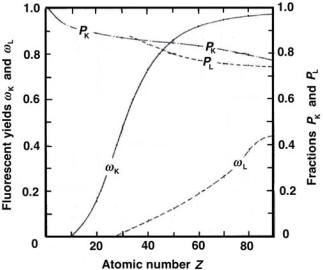
The fluorescent yield ω for a given shell gives the number of characteristic (fluorescent) photons emitted per vacancy in the given shell, as shown in Fig. 3.3 for the K and L shells versus the atomic number Z of the absorber.
The exact mechanism of energy transfer in the Auger e ect is di cult to calculate numerically. In the past, the e ect was often considered an internal atomic photoelectric e ect and the explanation makes sense energetically. However, two experimental facts contradict this assumption:
1.Auger e ect often results from forbidden radiative transitions, i.e., transitions that violate the selection rules for the radiative fluorescent process.
2.Fluorescent yield ω for high atomic number materials is significantly larger than that for low atomic number materials; contrary to the wellknown photoelectric e ect Z dependence that follows a Z3 behavior (see Sect. 7.5).

92 3 Production of X Rays
Fig. 3.3. Fluorescent yields ωK for hν > (EB)K and ωL for (EB)L < hν < (EB)K as well as fractions PK for hν > (EB)K and PL for (EB)L < hν < (EB)K against atomic number Z. Data are obtained from F.H. Attix, “Introduction to Radiological Physics and Radiation Dosimetry”
3.2 Emission of Radiation
by Accelerated Charged Particle (Bremsstrahlung Production)
Charged particles are characterized by their rest mass, charge, velocity and kinetic energy. With regard to their rest mass, charged particles of interest to medical physics and dosimetry are classified into two groups:
•light charged particles: electrons e− and positrons e+,
•heavy charged particles: protons p, deuterons d, alpha particles α, heavier ions such as Li+, Be+ C+, Ne+, etc.
3.2.1 Velocity of Charged Particles
→
With regard to its velocity υ a charged particle is:
1. |
→ |
|
|
stationary with υ = 0, |
|
|
|
2. |
moving with a uniform velocity υ = constant, |
||
3. |
accelerated with an acceleration |
|
→ |
a = dυ/dt. |
|||

3.2 Emission of Radiation by Accelerated Charged Particle |
93 |
Stationary Charged Particle
A stationary charged particle has an associated electric field E whose energy density ρ is given by
1 |
εoE2 , |
|
|
ρ = |
|
(3.2) |
|
2 |
|||
where εo is the dielectric constant (permittivity) of vacuum (εo |
= 8.85 × |
||
10−12 A · s/V · m). |
|
||
This energy is stored in the field and is not radiated away by the charged particle. The electric field E(r) produced by a stationary charged particle of charge q follows the inverse square law and is isotropic
E(r) = |
1 q |
(3.3) |
|||
|
|
|
. |
||
4πεo |
r2 |
||||
Charged Particle Moving with a Uniform Velocity |
|||||
|
|
|
|
|
→ |
A charged particle moving with a uniform velocity υ has an associated mag- |
|||||
|
|
|
|
|
|
netic field B as well as an electric field E. The energy density ρ is then given by
ρ = |
1 |
εoE2 + |
1 |
B2 , |
(3.4) |
2 |
2µo |
where µo is the magnetic permeability of vacuum (µo = 4π ×10−7 V·s/A·m). This energy is stored in the field, moves along with the charged particle,
and is not radiated away by the charged particle.
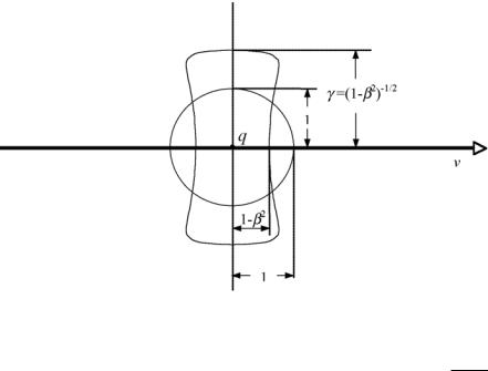
At low (classical) velocities υ the electric field E produced by the charged particle is isotropic and follows the inverse square law. However, as the velocity of the charged particle increases and approaches c, the speed of light in vacuum, the electric field decreases in the forward and backward direction and increases in a direction at right angles to the motion. As shown in Fig. 3.4, the electric field is contracted by a factor (1 − β2) in the direction of
the flight of the particle, whereas it is enhanced by a factor γ = 1/ |
1 |
− |
β2 |
in the transverse direction. |
|
|
The electric field distortion for moving charged particles is of importance in collision stopping power calculations. As a charged particle passes through an absorber, it sweeps out a cylinder throughout which its field is capable of transferring energy to orbital electrons of the absorber. The radius of this cylinder increases with increasing parameter γ as the charged particle velocity υ increases allowing more orbital electrons to be a ected by the charged particle, thereby increasing the energy loss, i.e., the stopping power, for the charged particle.

94 3 Production of X Rays
Fig. 3.4. Electric field produced by a charged particle q moving with uniform velocity υ in vacuum. The field is shown for two velocities: β = υ/c ≈ 0 (classical physics) and β = υ/c → 1. The electric field for β → 0 is isotropic, for relativistic velocities it is distorted; contracted by a factor (1 − β2) in the direction of motion
and opposite to the direction of motion, and expanded by a factor γ = 1/ 1 − β2 in directions perpendicular to the direction of motion
Accelerated Charged Particle
For an accelerated charged particle the non-static electric and magnetic fields cannot adjust themselves in such a way that no energy is radiated away from the charged particle. As a result, an accelerated or decelerated charged particle emits some of its kinetic energy in the form of photons (bremsstrahlung radiation), as discussed below.
3.2.2 Electric and Magnetic Fields Produced by Accelerated Charged Particles
Electric and magnetic fields associated with accelerated charged particles are calculated from Lienard-Wiechert potentials. To determine the fields at time t the potentials must be evaluated for an earlier time (called the retarded time), with the charged particle at a retarded position on its trajectory.
The electric and the magnetic field of an accelerated charged particle have two components:
1.local (or near) velocity field component which falls o as 1/r2,
2.far (or radiation) acceleration field component which falls o as 1/r.

3.2 Emission of Radiation by Accelerated Charged Particle |
95 |
At large distances r of interest in medical physics and dosimetry the 1/r radiation component dominates and the 1/r2 near field component may be ignored, since it approaches zero much faster than the 1/r component. The energy loss by radiation is thus determined by the far field components of
the |
electric field |
|
and the magnetic field |
|
. The far field components of |
|
||||||||||||||||||||||||
E |
B |
E |
||||||||||||||||||||||||||||
|
|
|
|
|
|
|
|
|
|
|
|
|
|
|
|
|
|
|
|
|
|
|
|
|
||||||
and B are given as follows |
|
|
|
|
|
|
|
|
|
|
|
|
|
|
|
|
|
|
||||||||||||
|
|
|
q |
|
|
|
→˙ |
|
|
|
|
|
1 q υ˙ sin θ |
|
|
|
|
|||||||||||||
|
E |
= |
|
r |
× ( r |
× υ) |
or |
E |
= |
|
|
|
(3.5) |
|||||||||||||||||
|
|
|
|
|
|
|
|
|
|
|
|
|
|
|
|
|
|
|||||||||||||
|
4πεo |
|
|
|
|
|
4πεo c2 r |
|
|
|||||||||||||||||||||
|
|
|
|
|
r3 |
|
|
|
|
|
|
|
||||||||||||||||||
|
and |
|
|
|
|
|
|
|
|
|
|
|
|
|
|
|
|
|
|
|
|
|
|
|
|
|
|
|
|
|
|
|
|
µo q |
→˙ |
× r |
|
|
|
|
|
|
|
µo |
|
q |
|
υ˙ sin θ |
|
|
|
|
|
|
|||||||
|
B |
= |
υ |
|
|
or |
B |
= |
|
|
|
= |
E |
, |
(3.6) |
|||||||||||||||
|
|
|
|
|
|
|
|
|
|
|
|
|||||||||||||||||||
|
|
4π c r2 |
|
|
|
|
|
|
4π c r |
c |
|
|
|
|||||||||||||||||
where
→
r is the radius vector connecting the charged particle with the point of observation,
→˙
υ is the acceleration of the charged particle, q is the charge of the charged particle,
θ is the angle between r and υ,
c is the speed of light in vacuum.
The E and B fields propagate outward with velocity c and form the electromagnetic (EM) radiation (bremsstrahlung) emitted by the accelerated charged particle.
3.2.3 Energy Density of the Radiation Emitted by Accelerated Charged Particle
The energy density ρ of the emitted radiation is given by
ρ = |
1 |
εoE2 + |
1 |
B2 = εoE2 , |
(3.7) |
2 |
2µo |
noting that B = E/c from (3.6) and c2 = 1/εoµo.
3.2.4 Intensity of the Radiation
Emitted by Accelerated Charged Particle
|
|
(r, θ), i.e., the energy flow per unit |
|
The intensity of the emitted radiation I |
|
||
, is given by the vector product |
E |
× B/µo, known as the Poynting |
|
area A |
|
||
vector S, where |
|
|
|
|
|
|
|
S = E × B/µo , |
(3.8) |

96 3 Production of X Rays
or, after using (3.5) and (3.6) and recognizing that E and B are perpendicular to one another
|
|
|
|
|
|
|
|
|
|
|
2 |
2 |
sin |
2 |
θ |
|
|
|||
|
S |
|
= |
I |
(r, θ) = |
EB |
= ε c |
E |
2 |
= |
1 q |
a |
|
. |
(3.9) |
|||||
|
|
|
|
|
|
|
|
|||||||||||||
|
16πεo c3 |
|
r2 |
|
||||||||||||||||
|
|
|
µo o |
|
|
|
|
|
|
|||||||||||
|
|
|
|
|
|
|
|
|
|
|
|
|
|
|
|
|
|
|
|
|
|
|
|
|
|
|
|
|
|
|
|
|
|
|
|
|
|
|
|
|
|
•The emitted radiation intensity I(r, θ) is linearly proportional to:
–q2, the square of particle’s charge
–a2, the square of particle’s acceleration,
–sin2 θ
•The emitted radiation intensity I(r, θ) is inversely proportional to r2, reflecting an inverse square law behavior.
•The emitted radiation intensity I(r, θ) exhibits a maximum at right angles to the direction of motion where θ = π/2. No radiation is emitted in the forward direction (θ = 0) or in the backward direction (θ = π).
3.2.5 Power Emitted by Accelerated Charged Particle Through Electromagnetic Radiation (Classical Larmor Relationship)
The power P (energy per unit time) emitted by the accelerated charged particle in the form of bremsstrahlung radiation is obtained by integrating the intensity I(r, θ) over the area A. Recognizing that dA = r2dΩ = 2πr2 sin θ dθ we obtain
P = dt |
= |
I(r, θ)dA = |
|
|
|
π |
I(r, θ)r2 sin θdθ |
||||||||
I(r, θ)r2dΩ =2π 0 |
|||||||||||||||
|
dE |
|
|
|
|
|
|
|
|
|
|
|
|
||
|
|
|
|
2π q2a2 |
2π |
|
|
1 q2a2 |
|
|
|||||
|
|
= |
|
0 |
sin3 θdθ = |
. |
(3.10) |
||||||||
|
|
16π2εo |
|
c3 |
6πεo |
|
c3 |
|
|||||||
Equation (3.10) is the classical Larmor relationship predicting that the power P emitted in the form of bremsstrahlung radiation by an accelerated charged particle is proportional to:
•q2, the square of particle’s charge
•a2, the square of particle’s acceleration.
The Larmor’s result represents one of the basic laws of nature and is of great importance to radiation physics. It can be expressed as follows:
“Any time a charged particle is accelerated or decelerated it emits part of its kinetic energy in the form of bremsstrahlung photons.”
As shown by the Larmor relationship of (3.10), the power emitted in the form of radiation depends on (qa)2 where q is the particle charge and a is its acceleration. The question arises on the e ciency of x-ray production for various charged particles of mass m and charge ze. As charged particles

3.2 Emission of Radiation by Accelerated Charged Particle |
97 |
interact with an absorber, they experience Coulomb interactions with orbital electrons (charge e) and nuclei (charge Ze) of the absorber. Bremsstrahlung is only produced through inelastic Coulomb interactions between a charged particle and the nucleus of the absorber.
The acceleration a produced in this type of Coulomb interaction can be evaluated through equating the Newton force with the Coulomb force, i.e.,
ma = |
zeZe |
, |
(3.11) |
|
4πεor2 |
||||
|
|
|
from where it follows that
a |
zZe2 |
(3.12) |
m , |
i.e., the acceleration a experienced by a charged particle interacting with absorbed nuclei is linearly proportional with: (1) the charge of the charged particle (ze) and (2) the charge of the absorber nucleus (Ze), and inversely proportional to: (1) the mass m of the charged particle and (2) the square of the distance between the two interacting particles r2.
Since it is proportional to a2, as shown in (3.10), the power of bremsstrahlung production is inversely proportional to m2. Thus a proton, by virtue of its relatively large mass mp in comparison with the electron mass me, (mp/me = 1836) will produce much less bremsstrahlung radiation than does an electron, specifically about (mp/me)2 ≈ 4 × 10⁶ times less. The radiative stopping power for electrons in comparison to that for protons is over six orders of magnitude greater at the same velocity.
•As a result of the inverse m2 dependence, heavy charged particles traversing a medium lose energy only through ionization (collision) losses and their radiative losses are negligible. These collision losses occur in interactions of the heavy charged particles with orbital electrons of the medium. The total stopping power for heavy charged particles is then given by the collision stopping power and their radiative stopping power is ignored, i.e., Stot = Scol.
•Light charged particles, on the other hand, undergo collision as well as radiative losses, since they interact with both the orbital electrons and the nuclei of the absorber. The total stopping power for light charged particles is then a sum of the collision stopping power and the radiative stopping power, i.e., Stot = Scol + Srad.
•As established in 1915 by William Duane and Franklin L. Hunt, the incident light particle can radiate an amount of energy which ranges from zero to the incident particle kinetic energy EK
EK = hνmax = 2π |
c |
, |
(3.13) |
|
|||
|
λmin |
|
|
producing a sharp cut-o at the short-wavelength end of the continuous bremsstrahlung spectrum (Duane-Hunt law ).

98 3 Production of X Rays
3.2.6 Relativistic Larmor Relationship |
|
||||||||||||
|
|
|
˙ |
|
˙ |
|
|
|
|
|
|
|
|
|
|
|
|
|
|
|
|
|
|
|
|
||
Recognizing that a = υ = p/m we can extend the classical Larmor result to |
|||||||||||||
relativistic velocities and obtain |
|
. |
dt |
. |
(3.14) |
||||||||
P = dt |
= 6πεo m2c3 |
dt |
|||||||||||
|
dE |
|
1 |
|
q2 |
|
|
|
|
|
|
||
|
|
|
|
|
|
|
|
|
|
|
|
|
|
|
|
|
|
|
|
|
|
|
|
|
|
|
|
|
|
|
|
|
|
|
|
|
|
|
|
|
|
|
|
|
|
|
|
|
|
|
|
|
|
|
|
For the special case of a linear motion (e.g., in a linear accelerator waveguide) the emitted power P is given as follows
|
dE |
|
1 q2 |
dp |
|
2 |
|
1 q2 |
dE |
|
2 |
|
||||||
P = |
|
= |
|
|
|
|
|
|
= |
|
|
|
|
|
, |
(3.15) |
||
dt |
6πεo |
m2c3 |
dt |
|
6πεo |
m2c3 |
dx |
|||||||||||
noting that the rate of change of momentum (dp/dt) is equal to the change in energy of the particle per unit distance (dE/dx).
3.2.7 Relativistic Electric Field
Produced by Accelerated Charged Particle
→
The velocity υ of the charged particle a ects the electric field E and, as β = υ/c increases, the electric field E becomes tipped forward and increases in magnitude as predicted by an expression di ering from the classical result of (3.5) by a factor 1/(1 − β cos θ)5/2
E(r, θ) = |
1 q υ˙ |
|
(√ |
sin θ |
(3.16) |
|||||||
|
|
|
|
|
|
|
)5 |
. |
||||
4πεo |
c2 |
r |
||||||||||
|
|
|
1 − β cos θ |
|||||||||
As a result, the emitted radiation intensity I(r, θ) also becomes tipped forward
S(r, θ) = I(r, θ) = εocE2 = |
1 q2a2 sin2 θ |
(3.17) |
|||||
|
|
|
|
|
. |
||
16πεo |
c3r2 |
(1 − β cos θ)5 |
|||||
Note that at classical velocities where β → 0, (3.16) and (3.17) revert to the classical relationships, given in (3.5) and (3.9), respectively.
•Equation (3.17) shows that the intensity I(r, θ) is in general proportional to sin2 θ/(1 − β cos θ)5. In classical mechanics where β → 0, the radiation
intensity is proportional to sin2 θ and the maximum intensity occurs at
θ = π/2.
•As β increases the radiation intensity becomes more and more forwardpeaked; however, the intensities for the forward direction (θ = 0) and the backward direction (θ = π) are still equal to zero, similarly to the classical situation.
•The function sin2 θ/(1 − β cos θ)5 that governs the radiation intensity distribution I(r, θ) of (3.17) is plotted in Fig. 3.5 for β = 0.006 (classical result for υ → 0) and for β = 0.941. For electrons (mec2 = 0.511 MeV) these two β values correspond to kinetic energies of 10 eV and 1 MeV, respectively.
