

B.Crowell - Electricity and Magnetism, Vol
.4.pdfExercise 4B: Reasoning About Circuits
The questions in this exercise can all be solved using some combination of the following approaches:
a)There is constant voltage throughout any conductor.
b)Ohm’s law can be applied to any part of a circuit.
c)Apply the loop rule.
d)Apply the junction rule.
It may be helpful to perform the actual experiments after having discussed the questions. Note, however, that some of the experiments may cause sparks, burn out your battery, or cause the wires to become hot enough to burn you.
1. A wire is added in parallel with one bulb.
6 V
Which reasoning is correct?
•Each bulb still has 3 V across it, so both bulbs are still lit up.
•All parts of a wire are at the same voltage, and there is now a wire connection from one side of the right-hand bulb to the other. The right-hand bulb has no potential difference across it, so it goes out.
2
6 V |
6 V |
Which reasoning is correct?
•Each bulb now has its sides connected to the two terminals of the battery, so each one now has 6 V across it instead of 3 V. They both get brighter.
•Just as in the original circuit, the current goes through one bulb, then the other. It's just that now the current goes in a figure-8 pattern. The bulbs glow the same as before.
3. A wire is added as shown to the original circuit.
What is wrong with the following reasoning?
The top bulb will go out, because its two sides are now connected with wire, so there will be no voltage difference across it. The other bulbs will not be affected.
4. A wire is added as shown to the original circuit.
What is wrong with the following reasoning?
The current flows out of the right-hand, positive terminal of the battery. When it hits the bottom junction, some of it will go left and some will keep going up The part that goes up lights the top bulb. The part that turns left then follows the path of least resistance, going through the new wire instead of the right-hand bulb. The top bulb stays lit, the bottom one goes out, and the left bulb stays the same.
This exercise is based on materials by Eric Mazur, Lillian McDermott, and Arnold Arons.
151
152
Exercise 5A - Field Vectors
Apparatus
2 solenoids
2 DC power supplies
2 ammeters compass ruler
cut-off plastic cup
At this point you’ve studied the gravitational field, g, and the electric field, E, but not the magnetic field, B. However, they all have some of the same mathematical behavior: they act like vectors. Furthermore, magnetic fields are the easiest to manipulate in the lab. Manipulating gravitational fields directly would require futuristic technology capable of moving planet-sized masses around! Playing with electric fields is not as ridiculously difficult, but static electric charges tend to leak off through your body to ground, and static electricity effects are hard to measure numerically. Magnetic fields, on the other hand, are easy to make and control. Any moving charge, i.e. any current, makes a magnetic field.
A practical device for making a strong magnetic field is simply a coil of wire, formally known as a solenoid. The field pattern surrounding the solenoid gets stronger or weaker in proportion to the amount of current passing through the wire. Your setup will consist of two solenoids, each driven by a power supply, with an ammeter to measure the current in each one.
1. With a single solenoid turned on and laid with its axis horizontal, use a magnetic compass to explore the field pattern inside and outside it. The compass shows you the field vector’s direction, but not its magnitude, at any point you choose. Note that the field the compass experiences is a combination (vector sum) of the solenoid’s field and the earth’s field.
2. What happens when you bring the compass extremely far away from the solenoid?
What does this tell you about the way the solenoid’s field varies with distance?
Thus although the compass doesn’t tell you the field vector’s magnitude numerically, you can get at least some general feel for how it depends on distance.
3. Make a sea-of-arrows sketch of the magnetic field in the horizontal plane containing the solenoid’s axis. The length of each arrow should at least approximately reflect the strength of the magnetic field at that point.
Does the field seem to have sources or sinks?
153
4. What do you think would happen to your sketch if you cut the current in half?
What will happen if you reverse the wires?
Try it.
5. Now turn on both solenoids. You are going to measure what happens when their two fields combine in the same region of space. As you’ve seen already, the solenoids’ nearby fields are much stronger than the earth’s field; so although we now theoretically have three fields involved (the earth’s plus the two solenoids’), it will be safe to ignore the earth’s field. The basic idea here is to place the solenoids with their axes at some angle to each other, and put the compass at the intersection of their axes, so that it is the same distance from each solenoid. Since the geometry doesn’t favor either solenoid, the only factor that would make one solenoid influence the compass more than the other is current. You can use the cut-off plastic cup as a little platform to bring the compass up to the same level as the solenoids’ axes.
a)What do you think will happen with the solenoids’ axes at 90 degrees to each other, and equal currents? Try it. Now represent the vector addition of the two magnetic fields with a diagram. Check your diagram with your instructor to make sure you’re on the right track.
b)Now try to make a similar diagram of what would happen if you switched the wires on one of the solenoids.
After predicting what the compass will do, try it and see if you were right.
c)Now suppose you were to go back to the arrangement you had in #1, but you changed one of the currents to half its former value. Make a vector addition diagram, and use trig to predict the angle.
Try it.
d)Now try an example where the currents are unequal, and the solenoids’ axes are at some angle other than 90 degrees. Calculate what will happen:
Try it.
154
Solutions to Selected Problems
Chapter 2
6. (a) In the reaction p+e– → n+ν, the charges on the left are e+(–e)=0, and both charges on the right are zero. (b) The neutrino has negligible mass. The masses on the left add up to less than the mass of the neutrino on the right, so energy would be required from an external source in order to make this reaction happen.
Chapter 3
12.t = q / I = e/I = 0.160 μs.
13.(a) The change in PE is eV, so the KE gained is (1/2)mv2=eV. Solving for v and plugging in numbers, we get 5.9x10⁷ m/s. This is about 20% of the speed of light, so the nonrelativistic assumption was good to at least a rough approximation.
Chapter 4
11.In series, they give 11 kΩ. In parallel, they give (1/1 kΩ+1/10 kΩ) –1 = 9 kΩ.
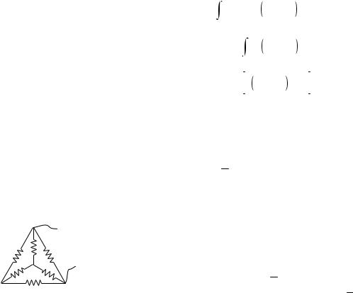
12.The actual shape is irrelevant; all we care about it what’s connected to what. Therefore, we can draw the circuit flattened into a plane. Every vertex of the tetrahedron is adjacent to every other vertex, so any two vertices to which we connect will give the same resistance. Picking two arbitrarily, we have this:
*
This is unfortunately a circuit that cannot be converted into parallel and series parts, and that’s what makes this a hard problem! However, we can recognize that by symmetry, there is zero current in the resistor marked with an asterisk. Eliminating this one, we recognize the whole arrangement as a triple parallel circuit consisting of resistances R, 2R, and 2R. The resulting resistance is R/2.
Chapter 5
9. Proceeding as suggested in the hint, we form
concentric rings, each one extending from radius b to radius b+db.The area of such a ring equals its circumference multipled by db, which is (2πb)db. Its charge is thus 2πσb db. Plugging this in to the expression from problem 8 gives a contribution to the field dE=2πσbka(a2+b2) –3/2db. The total field is found by integrating this expression. The relevant integral can be found in a table.
|
∞ |
– 3 |
/ 2 |
||||
E = |
2πσbka a2 + b 2 |
||||||
|
|
|
db |
||||
|
|
∞ |
– 3 / 2 |
||||
= |
2πσka b a2 + b 2 |
||||||
|
|
|
db |
||||
|
0 |
|
|
|
|
||
|
|
|
|
∞ |
|||
= |
2πσka |
– a2 + b 2 – 1 / 2 |
|
||||
|
|
|
|
|
|
b =0 |
|
|
|
|
|
|
|||
=2πσk
11. Let the square’s sides be of length a. The field at the center is the vector sum of the fields that would have been produced individually by the three charges. Each of these individual fields is kq/r2,
where r1=a /  2 for the two charges q1, and r2=a/2 for q2. Vector addition can be done by adding components. Let x be horizontal and y vertical. The y components cancel by symmetry. The sum of the x components is
E = |
kq |
1 |
/ r 2 |
° |
kq |
1 |
/ r 2 |
cos 45 |
° |
|
1 |
cos 45 + |
|
1 |
|
||||
x |
|
|
|
|
|
|
|
|
|
– kq2 / r 22 .
Substituting cos 45°=1 /  2 and setting this whole
expression equal to zero, we find q2/q1=1 /  2 .
2 .
Chapter 6
13. (a) Current means how much charge passes by a given point per unit time. During a time interval t, all the charge carriers in a certain region behind the point will pass by. This region has length v t and cross-sectional area A, so its volume is Av t, and the amount of charge in it is Avnq t. To find the current, we divide this amount of charge by t, giving I=Avnq.
(b) A segment of the wire of length L has a force QvB
Solutions to Selected Problems |
155 |
acting on it, where Q=ALnq is the total charge of the moving charge carriers in that part of the wire. The force per unit length is ALnqvB/L=AnqvB. (c) Dividing the two results gives F/L=IB.
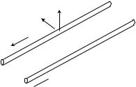
14. (a) The figure shows the case where the currents are in opposite directions.
B
F
I2
 I1
I1
The field vector shown is one made by wire 1, which causes an effect on wire 2. It points up because wire 1’s field pattern is clockwise as view from along the direction of current I1. For simplicity, let’s assume that the current I2 is made by positively charged particles moving in the direction of the current. (You can check that the final result would be the same if they were negatively charged, as would actually be the case in a metal wire.) The force on one of these positively charged particles in wire 2 is supposed to have a direction such that when you sight along it, the B vector is clockwise from the v vector. This can only be accomplished if the force on the particle in wire 2 is in the direction shown. Wire 2 is repelled by wire 1.
To verify that wire 1 is also repelled by wire 2, we can either go through the same type of argument again, or we can simply apply Newton’s third law.
Simialar arguments show that the force is attractive if the currents are in the same direction.
(b) The force on wire 2 is F/L=I2B, where B=μoI1/2πr is the field made by wire 1 and r is the distance between the wires. The result is
F/L = μoI1I2/2πr .
19. (a) Based on our knowledge of the field pattern of a current-carrying loop, we know that the magnetic field must be either into or out of the page. This makes sense, since that would mean the field is always perpendicular to the plane of the electrons’ motion; if it was in their plane of motion, then the angle between the v and B vectors would be changing all the time, but we see no evidence of such behavior. With the field turned on, the force vector is apparently toward the center of the circle. Let’s
analyze the force at the moment when the electrons have started moving, which is at the right side of the circle. The force is to the left. Since the electrons are negatively charged particles, we know that if we sight along the force vector, the B vector must be counterclockwise from the v vector. The magnetic field must be out of the page. (b) Looking at the figure earlier in section 6.2 that shows the field pattern of a circular loop of wire, we can tell that the current in the coils must be counterclockwise as viewed from the perspective of the camera. (c) Electrons are negatively charged, so to produce a counterclockwise current, the electrons in the coils must be going clockwise. (d) The current in the coils is keep the electrons in the beam from going straight, i.e. the force is a repulsion. This makes sense by comparison with problem 14: the coil currents and vacuum tube currents are counterrotating, which causes a repulsion.
20. Yes. For example, the force vanishes if the particle’s velocity is parallel to the field, so if the beam had been launched parallel to the field, it would have gone in a straight line rather than a circle. In general, any component of the velocity vector that is out of the plane perpendicular to the field will remain constant, so the motion can be helical.
156 |
Solutions to Selected Problems |

Glossary
Alpha decay. The radioactive decay of a nucleus via emission of an alpha particle.
Alpha particle. A form of radioactivity consisting of helium nuclei.
Ammeter. A device for measurin electrical current.
Ampere. The metric unit of current, one coulomb pe second; also “amp.”
Atom. The basic unit of one of the chemical elements.
Atomic mass. The mass of an atom.
Atomic number. The number of protons in an atom’s nucleus; determines what element it is.
Beta decay. The radioactive decay of a nucleus via the reaction n → p + e– + ν or p → n + e+ + n; so called because an electron or antielectron is also known as a beta particle.
Beta particle. A form of radioactivity consisting of electrons.
Cathode ray. The mysterious ray that emanated from the cathode in a vacuum tube; shown by Thomson to be a stream of particles smaller than atoms.
Charge. A numerical rating of how strongly an object participates in electrical forces.
Circuit. An electrical device in which charge can come back to its starting point and be recycled rather than getting stuck in a dead end.
Coulomb (C). The unit of electrical charge.
Current. The rate at which charge crosses a certain boundary.
Electric dipole. An object that has an imbalance between positive charge on one side and negative charge on the other; an object that will experience a torque in an electric field.
Electric field. The force per unit charge exerted on a test charge at a given point in space.
Electrical force. One of the fundamental forces of nature; a noncontact force that can be either repulsive or attractive.
Electron. Thomson’s name for the particles of which a cathode ray was made; a subatomic particle.
Field. A property of a point in space describing the forces that would be exerted on a particle if it was there.
Fission. The radioactive decay of a nucleus by splitting into two parts.
Fusion. A nuclear reaction in which two nuclei stick together to form one bigger nucleus.
Gamma ray. Aform of radioactivity consisting of a very high-frequency form of light.
Gravitational field. The force per unit mass exerted on a test mass at a given point in space.
Induction. The production of an electric field by a changing magnetic field, or vice-versa.
Ion. An electrically charged atom or molecule.
Isotope. One of the possible varieties of atoms of a given element, having a certain number of neutrons.
Magnetic dipole. An object, such as a current loop, an atom, or a bar magnet, that experiences torques due to magnetic forces; the strength of magnetic dipoles is measured by comparison with a standard dipole consisting of a square loop of wire of a given size and carrying a given amount of current.
Magnetic field. A field of force, defined in terms of the torque exerted on a test dipole.
Mass number. The number of protons plus the number of neutrons in a nucleus; approximately proportional to its atomic mass.
Millirem. A unit for measuring a person’s exposure to radioactivity; cf rem.
Molecule. A group of atoms stuck together.
Neutron. An uncharged particle, the other types that nuclei are made of.
Ohm. The metric unit of electrical resistance, one volt per ampere.
Ohmic. Describes a substance in which the flow of current between two points is proportional to the voltage difference between them.
Open circuit. A circuit that does not function because it has a gap in it.
157
Proton. A positively charged particle, one of the types that nuclei are made of.
Quantized. Describes quantity such as money or electrical charge, that can only exist in certain amounts.
Rem. A unit for measuring a person’s exposure to radioactivity; cf millirem.
Resistance. The ratio of the voltage difference to the current in an object made of an ohmic substance.
Short circuit. A circuit that does not function because charge is given a low-resistance “shortcut” path that it can follow, instead of the path that makes it do something useful.
Sink. A point at which field vectors converge.
Source. A point from which field vectors diverge; often used more inclusively to refer to points of either convergence or divergence.
Strong nuclear force. The force that holds nuclei together against electrical repulsion.
Volt. The metric unit of voltage, one joule per coulomb.
Voltage. Electrical potential energy per unit charge that will be posessed by a charged particle at a certain point in space.
Voltmeter. A device for measuring voltage differences.
Weak nuclear force. The force responsible for beta decay.
158
Index
A
alchemy 16 alpha radiation 43 ammeter 75 ampere (unit) 73 Aristotelianism 23 Aristotle 23
atom 22
planetary model of 45 raisin-cookie model of 35
atomic number 48 defined 48
Atomism 22
B
Becquerel 41 beta radiation 43 binding energy
nuclear 62 Brownian motion 27
C
capacitor 139 cathode rays 31 Cavendish 44 Chadwick, James 49 charge 18
conservation of 20 quantization of 28
Chernobyl 65 Church, Catholic 23 circuit 75
complete 75 open 75 parallel 86 series 86 short 83
complete circuit 75 conductor
defined 81 conservation of mass 22 coulomb (unit) 18 Coulomb’s law 19 Crookes, William 26 cross-section 51
Curie, Marie 43
Curie, Pierre 43 current
defined 73
D
dipole
electric 116 dipole moment 116 DNA 65
E
Einstein, Albert
and Brownian motion 27 electric current
defined 73 electric dipole 116 electric field 114
related to voltage 118 electric forces 17 electrolytes 88
electromagnetic spectrum 137 electromagnetic waves 136 electron 34
elements, chemical 25 energy
stored in fields 138 equivalent resistance
of resistors in parallel 97
F
Faraday , Michael 134 types of electricity 72 Feynman, Richard 142
field
electric 114 gravitational 112 magnetic 128
fields
superposition of 113 fields of force 109 force
fields of 109 Franklin, Benjamin
definition of signs of charge 19 fusion 61
G
Galileo 23, 132 gamma radiation 43 generator 134 gravitational field 112 gravitational waves 114
H
handedness 142 Hertz, Heinrich 137 Hiroshima 66 Hooke 16
Index 159
Hugo, Victor 15
I
induction 132 insulator
defined 81 isotopes 54
J
junction rule 97
K
Keynes, John Maynard 16
L
light
defined 24 loop rule 102
M
magnetic field 128
defined 129 |
|
magnetostatics |
130 |
Marsden 45 |
|
mass |
|
conservation of 22 |
|
matter |
|
defined 24 |
|
Maxwell, James Clerk 134 |
|
Mendeleev 48 |
|
Mendeleev, Dmitri 26 |
|
Millikan, Robert |
28 |
millirem (unit) 65 moment
dipole 116 monopoles
magnetic 128 Mosely, Henry 49
N
neutral (electrically) 19 neutron 53
Newton 132 Newton, Isaac 15
nuclear forces 56, 142 nucleus
discovery 46
O
ohmic defined 81
open circuit 75
P
parallel circuit defined 86
planetary model 45 polarization 136 proton 52
Q
quantization 28 quark 51
R
radar 127 radiation
types of 43
raisin cookie model 35 rem (unit) 65 resistance
defined 80 in parallel 97 in series 101
resistivity defined 102
resistor 84 resistors
in parallel 97 Rutherford 45 Rutherford , Ernest 44
S
schematic 96 schematics 96 scholasticism 23
sea-of-arrows representation 113 series circuit
defined 86 short circuit
defined 83 sinks in fields 113 solenoid 131
sources of fields 113 special relativity 63 spectrum
electromagnetic 137 strong nuclear force 56 sun
energy production 62 superposition of fields 113 symmetry 142
T
tesla (unit) 129 Thomson, J.J.
cathode ray experiments 32
160 Index