

B.Crowell - Electricity and Magnetism, Vol
.4.pdfThe figure shows the equations for some of the more commonly encountered configurations, with illustrations of their field patterns. Do not
memorize the equations! The symbol μo is an abbreviation for the constant 4πx10 –7 T.m/A. It is the magnetic counterpart of the Coulomb force
constant k. The Coulomb constant tells us how much electric field is produced by a given amount of charge, while μo relates currents to magnetic fields. Unlike k, μo has a definite numerical value because of the design of the metric system.
Field created by a long, straight wire carrying current I:
 I
I
I 
μoI
B = 2πr
Here r is the distance from the center of the wire. The field vectors trace circles in planes perpendicular to the wire, going clockwise when viewed from along the direction of the current.
Field created by a single circular loop of current:
The field vectors form a dipole-like pattern, coming through the loop and back around on the outside. Each oval path traced out by the field vectors appears clockwise if viewed from along the direction the current is going when it punches through it. There is no simple equation for the field at an arbitrary point in space, but for a point lying along the central axis perpendicular to the loop, the field is
– 3 / 2
B = 12μoIb2 b2 + z 2
 ,
,
where b is the radius of the loop and z is the distance of the point from the plane of the loop.
Field created by a solenoid (cylindrical coil):
The field pattern is similar to that of a single loop, but for a long solenoid the paths of the field vectors become very straight on the inside of the coil and on the outside immediately next to the coil. For a sufficiently long solenoid, the interior field also becomes very nearly uniform, with a magnitude of
B = μoIN / |
, |
|
where N is the number of turns of wire and |
is the length of |
|
I |
|
μoIn , where |
the solenoid. (Textbooks often give this as |
||
n = N /  is the number of turns per unit length.) The field near the mouths or outside the coil is not constant and more difficult to calculate. (There is a fairly simple equation for the field along the axis, inside and out, but we will not concern ourselves with it.) For a long solenoid, the exterior field is much smaller than the interior field.
Force on a charge moving through a magnetic field
We now know how to calculate magnetic fields in some typical situations, but one might also like to be able to calculate magnetic forces, such as the force of a solenoid on a moving charged particle, or the force between two parallel current-carrying wires.
We will restrict ourselves to the case of the force on a charged particle moving through a magnetic field, which allows us to calculate the force
Section 6.2 Calculating Magnetic Fields and Forces |
131 |
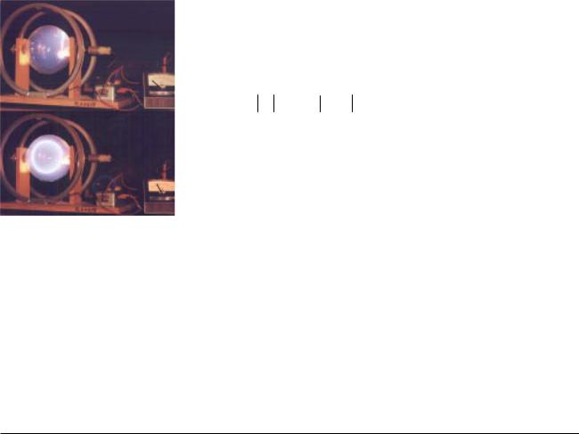
Magnetic forces cause a beam of electrons to move in a circle. The beam is created in a vacuum tube, in which a small amount of hydrogen gas has been left. A few of the electrons strike hydrogen molecules, creating light and letting us see the beam. A magnetic field is produced by passing a current (meter) through the circular coils of wire in front of and behind the tube. In the bottom figure, with the magnetic field turned on, the force perpendicular to the electrons’ direction of motion causes them to move in a circle.
between two objects when one is a moving charged particle and the other is one whose magnetic field we know how to find. An example is the use of solenoids inside a TV tube to guide the electron beam as it paints a picture.
Experiments show that the magnetic force on a moving charged particle has a magnitude given by
F = q v 
 B sin θ ,
where v is the velocity vector of the particle, and θ is the angle between the v and B vectors. Unlike electric and gravitational forces, magnetic forces do not lie along the same line as the field vector. The force is always perpendicular to both v and B. Given two vectors, there is only one line perpendicular to both of them, so the force vector points in one of the two possible directions along this line. For a positively charged particle, the direction of the force vector is the one such that if you sight along it, the B vector is clockwise from the v vector; for a negatively charged particle the direction of the force is reversed. Note that since the force is perpendicular to the particle’s motion, the magnetic field never does work on it.
Example: Hallucinations during an MRI scan
During an MRI scan of the head, the patient’s nervous system is exposed to intense magnetic fields. The average velocities of the charge-carrying ions in the nerve cells is fairly low, but if the patient moves her head suddenly, the velocity can be high enough that the magnetic field makes significant forces on the ions. This can result in visual and auditory hallucinations, e.g., frying bacon sounds.
6.3 Induction
Electromagnetism and relative motion
The theory of electric and magnetic fields constructed up to this point contains a paradox. One of the most basic principles of physics, dating back to Newton and Galileo and still going strong today, states that motion is relative, not absolute. Thus the laws of physics should not function any differently in a moving frame of reference, or else we would be able to tell which frame of reference was the one in an absolute state of rest. As an example from mechanics, imagine that a child is tossing a ball up and down in the back seat of a moving car. In the child’s frame of reference, the car is at rest and the landscape is moving by; in this frame, the ball goes straight up and down, and obeys Newton’s laws of motion and Newton’s law of gravity. In the frame of reference of an observer watching from the sidewalk, the car is moving and the sidewalk isn’t. In this frame, the ball follows a parabolic arc, but it still obeys Newton’s laws.
When it comes to electricity and magnetism, however, we have a problem, which was first clearly articulated by Einstein: if we state that magnetism is an interaction between moving charges, we have apparently created a law of physics that violates the principle that motion is relative, since different observers in different frames would disagree about how fast the charges were moving, or even whether they were moving at all. The incorrect solution that Einstein was taught (and disbelieved) as a student around the year 1900 was that the relative nature of motion applied only to mechanics, not to electricity and magnetism. The full story of how Einstein
132 |
Chapter 6 Electromagnetism |
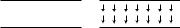
++ + + + + + + +
(a)A line of positive charges.
S
y
+
x
z
N
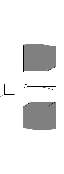
(b) Observer A sees a positively charged particle moves through a region of upward magnetic field, which we assume to be uniform, between the poles of two magnets. The resulting force along the z axis causes the particle’s path to curve toward us.
restored the principle of relative motion to its rightful place in physics involves his theory of special relativity, which we will not take up until book 6 of this series. However, a few simple and qualitative thought experiments will suffice to show how, based on the principle that motion is relative, there must be some new and previously unsuspected relationships between electricity and magnetism. These relationships form the basis for many practical, everyday devices, such as generators and transformers, and they also lead to an explanation of light itself as an electromagnetic phenomenon.
Let’s imagine an electrical example of relative motion in the same spirit as the story of the child in the back of the car. Suppose we have a line of positive charges, (a). Observer A is in a frame of reference which is at rest with respect to these charges, and observes that they create an electric field pattern that points outward, away from the charges, in all directions, like a bottle brush. Suppose, however, that observer B is moving to the right with respect to the charges. As far as B is concerned, she’s the one at rest, while the charges (and observer A) move to the left. In agreement with A, she observes an electric field, but since to her the charges are in motion, she must also observe a magnetic field in the same region of space, exactly like the magnetic field made by a current in a long, straight wire.
Who’s right? They’re both right. In A’s frame of reference, there is only an E, while in B’s frame there is both an E and a B. The principle of relative motion forces us to conclude that depending on our frame of reference we will observe a different combination of fields. Although we will not prove it (the proof requires special relativity, which we get to in book 6), it is true that either frame of reference provides a perfectly self-consistent description of things. For instance, if an electron passes through this region of space, both A and B will see it swerve, speed up, and slow down. A will successfully explain this as the result of an electric field, while B will ascribe the electron’s behavior to a combination of electric and magnetic forces.
Thus, if we believe in the principle of relative motion, then we must accept that electric and magnetic fields are closely related phenomena, two sides of the same coin.
Now consider figure (b). Observer A is at rest with respect to the bar magnets, and sees the particle swerving off in the z direction, as it should according to the rule given in section 6.2 (sighting along the force vector, i.e. from behind the page, the B vector is clockwise from the v vector).
Suppose observer B, on the other hand, is moving to the right along the x axis, initially at the same speed as the particle. B sees the bar magnets moving to the left and the particle initially at rest but then accelerating along the z axis in a straight line. It is not possible for a magnetic field to start a particle moving if it is initially at rest, since magnetism is an interaction of moving charges with moving charges. B is thus led to the inescapable conclusion that there is an electric field in this region of space, which points along the z axis. In other words, what A perceives as a pure B field, B sees as a mixture of E and B.
In general, observers who are not at rest with respect to one another will perceive different mixtures of electric and magnetic fields.
Section 6.3 Induction |
133 |
 B
B
E
E
B
(c) The geometry of induced fields. The induced field tends to form a whirlpool pattern around the change in the vector producing it. Note how they circulate in opposite directions.
The principle of induction
So far everything we’ve been doing might not seem terribly useful, since it seems that nothing surprising will happen as long as we stick to a single frame of reference, and don’t worry about what people in other frames think. That isn’t the whole story, however, as was discovered experimentally by Faraday in 1831and explored mathematically by Maxwell later in the same century. Let’s state Faraday’s idea first, and then see how something like it must follow inevitably from the principle that motion is relative:
the principle of induction
Any electric field that changes over time will produce a magnetic field in the space around it.
Any magnetic field that changes over time will produce an electric field in the space around it.
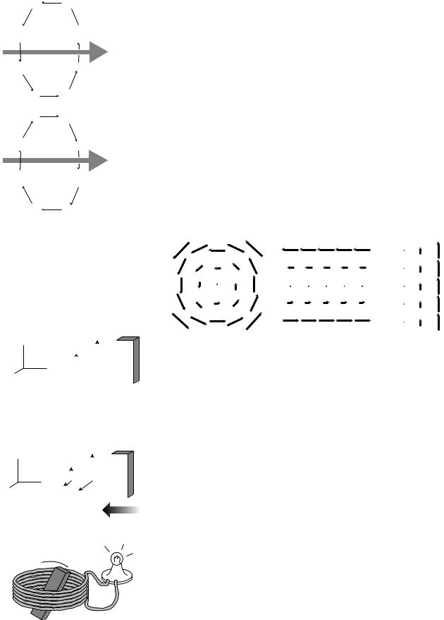
The induced field tends to have a whirlpool pattern, as shown in figure (c), but the whirlpool image is not to be taken too literally; the principle of induction really just requires a field pattern such that, if one inserted a paddlewheel in it, the paddlewheel would spin. All of the field patterns shown in the following figure are ones that could be created by induction; all have a counterclockwise “curl” to them:
y |
B |
|
|||
B |
|
|
S |
||
|
|
|
|
||
x |
|
|
|
|
|
|
|
|
|
||
z |
|
|
N |
||
(d) Observer A is at rest with respect to the bar magnet, and observes magnetic fields that have different strengths at different distances from the magnet.
|
y |
B |
B |
|
||
z |
x |
|
|
S |
||
|
|
|
|
N |
||
|
|
|
|
|||
|
|
|
|
|||
E |
|
E |
|
|
||
|
|
|
|
|
|
|
(f) A generator.
Figures (d) and (e) show an example of the fundamental reason why a changing B field must create an E field. The electric field would be inexplicable to observer B if she believed only in Coulomb’s law, and thought that all electric fields are made by electric charges. If she knows about the principle of induction, however, the existence of this field is to be expected.
(e) Observer B, hanging out in the region to the left of the magnet, sees the magnet moving toward her, and detects that the magnetic field in that region is getting stronger as time passes. As in figure (b), there is an electric field along the z axis because she’s in motion with respect to the magnet. The B vector is upward, and the electric field has a curliness to it: a paddlewheel inserted in the electric field would spin clockwise as seen from above, since the clockwise torque made by the strong electric field on the right is greater than the counterclockwise torque made by the weaker electric field on the left.
Example: the generator
A generator, (f), consists of a permanent magnet that rotates within a coil of wire. The magnet is turned by a motor or crank, (not shown). As it spins, the nearby magnetic field changes. According to the principle of induction, this changing magnetic field results in an electric field, which has a whirlpool pattern. This electric field pattern creates a current that whips around the coils of wire, and we can tap this current to light the lightbulb.
134 |
Chapter 6 Electromagnetism |
Self-Check
output — low voltage high current
input —
high voltage low current
(g) A transformer.
When you’re driving your car, the engine recharges the battery continuously using a device called an alternator, which is really just a generator like the one shown on the previous page, except that the coil rotates while the permanent magnet is fixed in place. Why can’t you use the alternator to start the engine if your car’s battery is dead?
Example: the transformer
In section 4.3 we discussed the advantages of transmitting power over electrical lines using high voltages and low currents. However, we don’t want our wall sockets to operate at 10000 volts! For this reason, the electric company uses a device called a transformer, (g), to convert to lower voltages and higher currents inside your house. The coil on the input side creates a magnetic field. Transformers work with alternating current, so the magnetic field surrounding the input coil is always changing. This induces an electric field, which drives a current around the output coil.
If both coils were the same, the arrangement would be symmetric, and the output would be the same as the input, but an output coil with a smaller number of coils gives the electric forces a smaller distance through which to push the electrons. Less mechanical work per unit charge means a lower voltage. Conservation of energy, however, guarantees that the amount of power on the output side must equal the amount put in originally, IinVin=IoutVout, so this reduced voltage must be accompanied by an increased current.
Discussion Question
In figures (b), (d), and (e), observer B is moving to the right. What would have happened if she had been moving to the left?
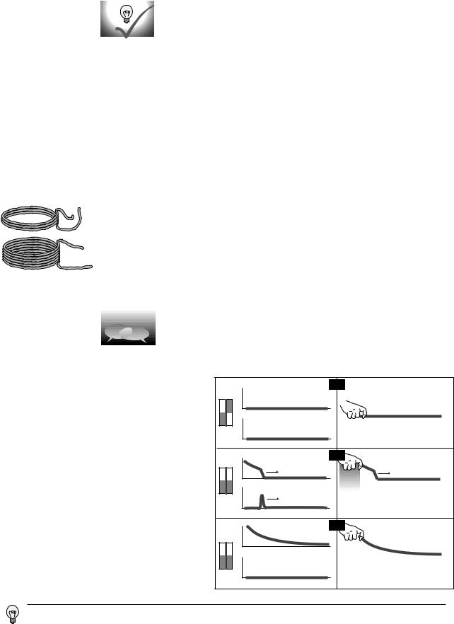
An example of induction (left) with a mechanical analogy (right). The two bar magnets are initially pointing in opposite directions, (a), and their magnetic fields cancel out. If one magnet is flipped, (b), their fields reinforce, but the change in the magnetic field takes time to spread through space. Eventually, (c), the field becomes what you would expect from the theory of magnetostatics. In the mechanical analogy, the sudden motion of the hand produces a violent kink or wave pulse in the rope, the pulse travels along the rope, and it takes some time for the rope to settle down. An electric field is also induced in (b) by the changing magnetic field, even though there is no net charge anywhere to to act as a source. (These simplified drawings are not meant to be accurate representations of the complete three-dimensional pattern of electric and magnetic fields.)
B |
(a) |
E |
distance |
B |
distance |
(b) |
|
E |
distance |
B |
distance |
(c) |
Edistance
distance
An induced electric field can only be created by a changing magnetic field. Nothing is changing if your car is just sitting there. A point on the coil won’t experience a changing magnetic field unless the coil is already spinning, i.e. the engine has already turned over.
Section 6.3 Induction |
135 |
|
direction of motion of wave |
|
|
|
|
E |
B |
E |
B |
E |
B |
|
|
|
|||
B |
E |
B |
|
B |
E |
|
|
E |
|||
plane of |
|
|
|
|
|
vibration |
|
|
|
plane of vibration |
|
of electric |
|
|
|
of magnetic field |
|
field |
|
|
|
|
|
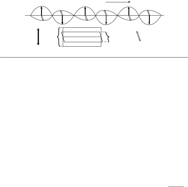
6.4 Electromagnetic Waves
The most important consequence of induction is the existence of electromagnetic waves. Whereas a gravitational wave would consist of nothing more than a rippling of gravitational fields, the principle of induction tells us that there can be no purely electrical or purely magnetic waves. Instead, we have waves in which there are both electric and magnetic fields, such as the sinusoidal one shown in the figure. Maxwell proved that such waves were a direct consequence of his equations, and derived their properties mathematically. The derivation would be beyond the mathematical level of this book, so we will just state the results.
A sinusoidal electromagnetic wave has the geometry shown in the figure above. The E and B fields are perpendicular to the direction of motion, and are also perpendicular to each other. If you look along the direction of motion of the wave, the B vector is always 90 degrees clockwise from the E vector. The magnitudes of the two fields are related by the equation |E|=c|B|.
How is an electromagnetic wave created? It could be emitted, for example, by an electron orbiting an atom or currents going back and forth in a transmitting antenna. In general any accelerating charge will create an electromagnetic wave, although only a current that varies sinusoidally with time will create a sinusoidal wave. Once created, the wave spreads out through space without any need for charges or currents along the way to keep it going. As the electric field oscillates back and forth, it induces the magnetic field, and the oscillating magnetic field in turn creates the electric field. The whole wave pattern propagates through empty space at a velocity
c=3.0x10⁸ m/s, which is related to the constants k and μo by c= 4πk / μo .
Polarization
Two electromagnetic waves traveling in the same direction through space can differ by having their electric and magnetic fields in different directions, a property of the wave called its polarization.
Light is an electromagnetic wave
Once Maxwell had derived the existence of electromagnetic waves, he became certain that they were the same phenomenon as light. Both are transverse waves (i.e. the vibration is perpendicular to the direction the wave is moving), and the velocity is the same. He is said to have gone for a walk with his wife one night and told her that she was the only other person in the world who knew what starlight really was.
136 |
Chapter 6 Electromagnetism |

|
|
|
|
|
|
the electromagnetic |
|
|
|
|
|
|
|
|
|
|
|
|
|
|
|
visible light |
|
|
|
|
|
|
|
|
|
|
|
|
|
|
|
|
|
|
|
|
|
|
|
|
|
|
|
|
|
|
|
|
|
|
|||||||||||||||||||||||||||||||||||||||||||||
|
|
|
|
|
|
|
|
|
|
|
|
|
|
|
|
|
|
|
|
|
red |
|
|
|
|
|
violet |
|
|
|
|
|
|
|
|
|
|
|
|
|
|
|
|
|
|
|
|
|
gamma |
|
|
|
rays |
|
|
|
|
||||||||||||||||||||||||||||||||||||||||||||
|
|
|
|
|
|
|
|
|
|
|
|
|
|
|
|
|
|
|
|
|
|
|
|
|
|
|
|
|
|
|
|
|
|
|
|
|
|
|
|
|
|
|
|
|
|
|
|
|
|
|
|
|
|
||||||||||||||||||||||||||||||||||||||||||||||||
|
|
|
|
|
|
spectrum |
|
|
|
|
|
|
|
|
|
|
|
|
|
|
|
|
|
|
|
|
|
|
|
|
|
|
|
|
|
|
|
|
|
|
|
|
|
|
|
|
|
|
|
|
|
|
|
|
|
|
|
x |
- |
|
rays |
|
|
|
|
|
|
|
|
|
|
||||||||||||||||||||||||||||||
|
|
|
|
|
|
|
|
|
|
|
|
|
|
|
|
|
|
|
|
|
|
|
|
|
|
|
|
|
|
|
|
|
|
|
|
|
|
|
|
|
|
|
|
|
|
|
|
|
|
|
|
|
|
|
|
|
|
|
|
|
|
|
|
|
|
|
|
||||||||||||||||||||||||||||||||||
|
|
|
|
|
|
|
|
|
|
|
radio |
|
|
|
|
|
|
|
|
|
|
|
|
|
|
|
microwaves |
|
|
|
|
|
|
|
|
infrared |
|
|
|
|
|
|
|
|
|
|
|
|
ultraviolet |
|
|
|
|
|
|
|
|
|
|
|
|
|
|
|
|
|
|
|
|
|
|
|
|
|
|
|
|
|
|
|
|
||||||||||||||||||||
|
|
|
|
|
|
|
|
|
|
|
|
|
|
|
|
|
|
|
|
|
|
|
|
|
|
|
|
|
|
|
|
|
|
|
|
|
|
|
|
|
|
|
|
|
|
|
|
|
|
|
|
|
|
|
|
|
|
|
|
|
|
|
|
|
|
|
|
|
|
|
|
|
|
|
|
|
|
||||||||||||||||||||||||
|
|
|
|
|
|
|
|
|
|
|
|
|
|
|
|
|
|
|
|
|
|
|
|
|
|
|
|
|
|
|
|
|
|
|
|
|
|
|
|
|
|
|
|
|
|
|
|
|
|
|
|
|
|
|
|
|
|
|
|
|
|
|
|
|
|
|
|
|
|
|
|
|
|
|
|
|
|
|
|
|
|
|
|
|
|
|
|
|
|
|
|||||||||||
|
|
|
|
|
|
|
|
|
|
|
|
|
|
|
|
|
|
|
|
|
|
|
|
|
|
|
|
|
|
|
|
|
|
|
|
|
|
|
|
|
|
|
|
|
|
|
|
|
|
|
|
|
|
|
|
|
|
|
|
|
|
|
|
|
|
|
|
|
|
|
|
|
|
|
|
|
|
|
|
|
|
|
|
|
|
|
|
|
|
||||||||||||
|
|
|
|
|
|
|
|
|
|
|
|
|
|
|
|
|
|
|
|
|
|
|
|
|
|
|
|
|
|
|
|
|
|
|
|
|
|
|
|
|
|
|
|
|
|
|
|
|
|
|
|
|
|
|
|
|
|
|
|
|
|
|
|
|
|
|
|
|
|
|
|
|
|
|
|
|
|
|
|
|
|
|
|
|
|
|
|
|
|
|
|
|
|
|
|
||||||
|
|
|
|
|
|
|
|
|
|
|
|
|
|
|
|
|
|
|
|
|
|
|
|
|
|
|
|
|
|
|
|
|
|
|
|
|
|
|
|
|
|
|
|
|
|
|
|
|
|
|
|
|
|
|
|
|
|
|
|
|
|
|
|
|
|
|
|
|
|
|
|
|
|
|
|
|
|
|
|
|
|
|
|
|
|
|
|
|
|
|
|
|
|
|
|
||||||
|
|
|
|
|
|
|
|
|
|
|
|
|
|
|
|
|
|
|
|
|
|
|
|
|
|
|
|
|
|
|
|
|
|
|
|
|
|
|
|
|
|
|
|
|
|
|
|
|
|
|
|
|
|
|
|
|
|
|
|
|
|
|
|
|
|
|
|
|
|
|
|
|
|
|
|
|
|
|
|
|
|
|
|
|
|
|
|
|
|
|
|
|
|
|
|
|
|
|
|
|
|
10 |
|
3 |
|
|
10 |
|
2 |
|
|
|
10 |
|
1 |
|
|
|
10 |
|
0 |
|
|
10 |
|
-1 |
|
|
|
10 |
|
-2 10 |
|
-3 |
10 |
|
-4 10 |
|
-5 10 |
|
-6 |
|
10 |
|
-7 10 |
|
-8 10 |
|
-9 10 |
|
|
-10 |
10 |
|
-11 10 |
|
-12 10 |
|
-13 |
||||||||||||||||||||||||||||||||||||||||||||
|
|
|
|
|
|
|
|
|
|
|
|
|
|
|
|
|
|
||||||||||||||||||||||||||||||||||||||||||||||||||||||||||||||||||||||||||||||||||||
|
|
|
|
|
|
|
|
|
|
|
|
|
|
|
|
|
|
|
|
|
|
|
|
|
|
|
|
|
|
|
|
|
|
|
|
|
|
|
|
|
|
|
wavelength (m) |
|
|
|
|
|
|
|
|
|
|
|
|
|
|
|
|
|
|
|
|
|
|
|
|
|
|
|
|
|
|
|
|
|
|
|
|
|
|
|
|
|
|
|
|
|
|||||||||||||
|
|
|
|
|
|
|
|
6 |
|
|
|
7 |
|
|
|
|
8 |
|
|
|
|
|
9 |
|
|
|
|
10 |
|
|
|
|
11 |
|
|
|
|
|
12 |
|
|
|
|
13 |
|
|
|
14 |
|
|
|
|
15 |
|
|
|
|
16 |
|
|
|
|
|
|
17 |
|
|
|
|
|
18 |
|
|
|
19 |
|
|
|
|
20 |
|
|
|
||||||||||||||||||
10 |
|
5 |
10 |
|
10 |
|
10 |
|
10 |
|
10 |
|
|
10 |
|
10 |
|
|
10 |
|
|
10 |
|
10 |
|
|
10 |
|
|
10 |
|
|
|
|
10 |
|
10 |
|
10 |
|
|
|
|
||||||||||||||||||||||||||||||||||||||||||||||||||||||||||
|
|
|
|
|
|
|
|
|
|
|
|
|
|
|
|
|
|
|
|
|
|
||||||||||||||||||||||||||||||||||||||||||||||||||||||||||||||||||||||||||||||||
|
|
|
|
|
|
|
|
|
|
|
|
|
|
|
|
|
|
|
|
|
|
|
|
|
|
|
|
|
|
|
|
|
|
|
|
|
|
|
|
|
|
|
frequency (Hz) |
|
|
|
|
|
|
|
|
|
|
|
|
|
|
|
|
|
|
|
|
|
|
|
|
|
|
|
|
|
|
|
|
|
|
|
|
|
|
|
|
|
|
|
|
|
|||||||||||||
Heinrich Hertz (for whom the unit of frequency is named) verified Maxwell’s ideas experimentally. Hertz was the first to succeed in producing, detecting, and studying electromagnetic waves in detail using antennas and electric circuits. To produce the waves, he had to make electric currents oscillate very rapidly in a circuit. In fact, there was really no hope of making the current reverse directions at the frequencies of 1015 Hz possessed by visible light. The fastest electrical oscillations he could produce were 109 Hz, which would give a wavelength of about 30 cm. He succeeded in showing that, just like light, the waves he produced were polarizable, and could be reflected and refracted (i.e. bent, as by a lens), and he built devices such as parabolic mirrors that worked according to the same optical principles as those employing light. Hertz’s results were convincing evidence that light and electromagnetic waves were one and the same.
The electromagnetic spectrum
Today, electromagnetic waves with frequencies in the range employed by Hertz are known as radio waves. Any remaining doubts that the “Hertzian waves,” as they were then called, were the same type of wave as light waves were soon dispelled by experiments in the whole range of frequencies in between, as well as the frequencies outside that range. In analogy to the spectrum of visible light, we speak of the entire electromagnetic spectrum, of which the visible spectrum is one segment.
The terminology for the various parts of the spectrum is worth memorizing, and is most easily learned by recognizing the logical relationships between the wavelengths and the properties of the waves with which you are already familiar. Radio waves have wavelengths that are comparable to the size of a radio antenna, i.e. meters to tens of meters. Microwaves were named that because they have much shorter wavelengths than radio waves; when food heats unevenly in a microwave oven, the small distances between neighboring hot and cold spots is half of one wavelength of the standing wave the oven creates. The infrared, visible, and ultraviolet obviously have much shorter wavelengths, because otherwise the wave nature of light would have been as obvious to humans as the wave nature of ocean waves. To remember that ultraviolet, x-rays, and gamma rays all lie on the shortwavelength side of visible, recall that all three of these can cause cancer. (As we’ll discuss later in the course, there is a basic physical reason why the cancer-causing disruption of DNA can only be caused by very shortwavelength electromagnetic waves. Contrary to popular belief, microwaves cannot cause cancer, which is why we have microwave ovens and not x-ray ovens!)
Section 6.4 Electromagnetic Waves |
137 |

6.5 Calculating Energy in Fields
We have seen that the energy stored in a wave (actually the energy density) is typically proportional to the square of the wave’s amplitude. Fields of force can make wave patterns, for which we might expect the same to be true. This turns out to be true not only for wave-like field patterns but for all fields:
|
3 |
= – |
1 |
|
|
|
g |
|
2 |
|||||
|
|
|
|
|
||||||||||
energy stored in the gravitational field per m |
8πG |
|
|
|
|
|
|
|
|
|||||
|
|
|
|
|
|
|
|
|
|
|||||
3 |
|
|
|
1 |
|
|
|
E |
|
|
|
|
2 |
|
|
|
|
|
|
|
|
||||||||
energy stored in the electric field per m |
|
= |
|
8πk |
|
|
|
|
|
|
|
|
|
|
|
|
|
|
|
|
|
|
|
|
|
|
|||
energy stored in the magnetic field per m |
3 |
= |
|
1 |
|
|
|
B |
|
|
2 |
|||
|
|
|
|
|
||||||||||
|
|
2μo |
|
|
|
|
|
|
|
|
|
|||
|
|
|
|
|
|
|
|
|
|
|
|
|||
Although funny factors of 8π and the plus and minus signs may have initially caught your eye, they are not the main point. The important idea is that the energy density is proportional to the square of the field strength in all three cases. We first give a simple numerical example and work a little on the concepts and then turn our attention to the factors out in front.
Example: Getting killed by a solenoid
Solenoids are very common electrical devices, but they can be a hazard to someone who is working on them. Imagine a solenoid that initially has a DC current passing through it. The current creates a magnetic field inside and around it, which contains energy. Now suppose that we break the circuit. Since there is no longer a complete circuit, current will quickly stop flowing, and the magnetic field will collapse very quickly. The field had energy stored in it, and even a small amount of energy can create a dangerous power surge if released over a short enough time interval. It is prudent not to fiddle with a solenoid that has current flowing through it, since breaking the circuit could be hazardous to your health.
As a typical numerical estimate, let’s assume a 40 cm x 40 cm x 40 cm solenoid with an interior magnetic field of 1.0 T (quite a strong field). For the sake of this rough estimate, we ignore the exterior field, which is weak, and assume that the solenoid is cubical in shape. The energy stored in the field is
(energy per unit volume)(volume)
|
1 |
|
B |
|
2 |
|
|
|
|||
= |
2μo |
|
|
V |
|
|
|
|
|
|
= 3x10 4 J
That’s a lot of energy!
138 |
Chapter 6 Electromagnetism |
++ + + + + +
–– – – – – –
(a)(b)
In chapter 5 when we discussed the original reason for introducing the concept of a field of force, a prime motivation was that otherwise there was no way to account for the energy transfers involved when forces were delayed by an intervening distance. We used to think of the universe’s energy as consisting of
kinetic energy
+gravitational potential energy based on the distances between objects that interact gravitationally
+electric potential energy based on the distances between objects that interact electrically
+magnetic potential energy based on the distances between objects that interact magnetically
but in nonstatic situations we must use a different method:
kinetic energy
+gravitational potential energy stored in gravitational fields
+electric potential energy stored in electric fields
+magnetic potential stored in magnetic fields
Surprisingly, the new method still gives the same answers for the static cases.
Example: energy stored in a capacitor
A pair of parallel metal plates, seen from the side in figures
(a) and (b), can be used to store electrical energy by putting positive charge on one side and negative charge on the other. Such a device is called a capacitor. (We have encountered such an arrangement previously, but there its purpose was to deflect a beam of electrons, not to store energy.)
In the old method of describing potential energy, (a), we think in terms of the mechanical work that had to be done to separate the positive and negative charges onto the two plates, working against their electrical attraction. The new description, (b), attributes the storage of energy to the newly created electric field occupying the volume between the plates. Since this is a static case, both methods give the same, correct answer.
Section 6.5 Calculating Energy in Fields |
139 |
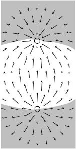
Example: potential energy of a pair of opposite charges
Imagine taking two opposite charges, (c), that were initially far apart and allowing them to come together under the influence of their electrical attraction.
–
According to the old method, potential energy is lost because the electric force did positive work as it brought the charges
|
|
|
|
|
together. (This makes sense because as they come together and |
|||||||||||||||||||
|
|
|
|
|
accelerate it is their potential energy that is being lost and |
|
|
|||||||||||||||||
|
|
|
|
|
converted to kinetic energy.) |
|
|
|
|
|
|
|
|
|
|
|
|
|
|
|
|
|||
|
|
|
|
|
By the new method, we must ask how the energy stored in |
|
|
|||||||||||||||||
|
|
|
|
|
|
|
||||||||||||||||||
|
|
|
|
|
the electric field has changed. In the region indicated approxi- |
|
|
|||||||||||||||||
|
|
|
|
|
mately by the shading in the figure, the superposing fields of the |
|
||||||||||||||||||
|
|
|
|
|
two charges undergo partial cancellation because they are in |
|
|
|||||||||||||||||
+ |
|
opposing directions. The energy in the shaded region is reduced |
|
|||||||||||||||||||||
|
|
|
|
|
by this effect. In the unshaded region, the fields reinforce, and |
|
|
|||||||||||||||||
|
|
|
|
|
|
|||||||||||||||||||
|
|
|
|
|
the energy is increased. |
|
|
|
|
|
|
|
|
|
|
|
|
|
|
|
|
|||
|
|
|
|
|
|
|
|
|
|
|
|
|
|
|
|
|
|
|
|
|||||
|
|
|
|
|
It would be quite a project to do an actual numerical calcula- |
|
||||||||||||||||||
|
|
|
|
|
tion of the energy gained and lost in the two regions (this is a |
|
|
|||||||||||||||||
|
|
|
|
|
|
|||||||||||||||||||
(c) |
|
case where the old method of finding energy gives greater ease |
|
|||||||||||||||||||||
|
of computation), but it is fairly easy to convince oneself that the |
|
||||||||||||||||||||||
|
|
|
|
|
|
|||||||||||||||||||
|
|
|
|
|
energy is less when the charges are closer. This is because |
|
|
|||||||||||||||||
|
|
|
|
|
bringing the charges together shrinks the high-energy unshaded |
|
||||||||||||||||||
|
|
|
|
|
region and enlarges the low-energy shaded region. |
|
|
|
|
|
|
|
||||||||||||
|
|
|
|
|
Example: energy in an electromagnetic wave |
|
|
|
|
|
|
|
|
|
|
|||||||||
|
|
|
|
|
The old method would give zero energy for a region of space |
|
|
|||||||||||||||||
|
|
|
|
|
containing an electromagnetic wave but no charges. That would |
|
||||||||||||||||||
|
|
|
|
|
be wrong! We can only use the old method in static cases. |
|
|
|||||||||||||||||
|
|
|
|
|
Now let’s give at least some justification for the other features of the |
|
|
|||||||||||||||||
|
|
|
|
1 |
|
g |
|
2 |
|
1 |
|
E |
|
2 |
|
1 |
|
|
B |
|
2 |
|
||
|
|
|
|
|
|
|
|
|
|
|
|
|
||||||||||||
|
|
|
|
|
three expressions for energy density, – |
|
|
|
|
, |
|
|
|
|
, and |
|
|
|
|
|
, |
|||
|
|
|
|
8πG |
|
|
8πk |
|
|
2μo |
|
|||||||||||||
|
|
|
|
|
|
|
|
|
|
|
|
|
|
|
|
|
|
|
|
|||||
besides the proportionality to the square of the field strength.
First, why the different plus and minus signs? The basic idea is that the signs have to be opposite in the gravitational and electric cases because there is an attraction between two positive masses (which are the only kind that exist), but two positive charges would repel. Since we’ve already seen examples where the positive sign in the electric energy makes sense, the gravitational energy equation must be the one with the minus sign.
140 |
Chapter 6 Electromagnetism |