

B.Crowell - Electricity and Magnetism, Vol
.4.pdfSummary
Selected Vocabulary |
|
current ................................... |
the rate at which charge crosses a certain boundary |
ampere ................................... |
the metric unit of current, one coulomb pe second; also “amp” |
ammeter ................................. |
a device for measuring electrical current |
circuit ..................................... |
an electrical device in which charge can come back to its starting point |
|
and be recycled rather than getting stuck in a dead end |
open circuit ............................ |
a circuit that does not function because it has a gap in it |
short circuit ............................ |
a circuit that does not function because charge is given a low-resistance |
|
“shortcut” path that it can follow, instead of the path that makes it do |
|
something useful |
voltage .................................... |
electrical potential energy per unit charge that will be possessed by a |
|
charged particle at a certain point in space |
volt ......................................... |
the metric unit of voltage, one joule per coulomb |
voltmeter ................................ |
a device for measuring voltage differences |
ohmic ..................................... |
describes a substance in which the flow of current between two points |
|
is proportional to the voltage difference between them |
resistance ................................ |
the ratio of the voltage difference to the current in an object made of |
|
an ohmic substance |
ohm ....................................... |
the metric unit of electrical resistance, one volt per ampere |
Notation |
|
I ........................................ |
current |
A ....................................... |
units of amperes |
V ....................................... |
voltage |
V ....................................... |
units of volts |
R ....................................... |
resistance |
Ω....................................... |
units of ohms |
Notation and Terminology Used in Other Books |
|
electric potential ................ |
rather than the more informal “voltage” used here; despite the misleading |
|
name, it is not the same as electric potential energy |
eV ..................................... |
a unit of energy, equal to e multiplied by 1 volt; 1.6x10 –19 joules |
Summary
All electrical phenomena are alike in that that arise from the presence or motion of charge. Most practical electrical devices are based on the motion of charge around a complete circuit, so that the charge can be recycled and does not hit any dead ends. The most useful measure of the flow of charge is current, I= q/ t.
An electrical device whose job is to transform energy from one form into another, e.g. a lightbulb, uses power at a rate which depends both on how rapidly charge is flowing through it and on how much work is done on each unit of charge. The latter quantity is known as the voltage difference between the point where the current enters the device and the point where the current leaves it. Since there is a type of potential energy associated with electrical forces, the amount of work they do is equal to the difference in potential energy between the two points, and we therefore define voltage differences directly in terms of potential energy, V= PEelec/q. The rate of power dissipation is P=I V.
Many important electrical phenomena can only be explained if we understand the mechanisms of current flow at the atomic level. In metals, currents are carried by electrons, in liquids by ions. Gases are normally poor conductors unless their atoms are subjected to such intense electrical forces that the atoms become ionized.
Many substances, including all solids, respond to electrical forces in such a way that the flow of current between two points is proportional to the voltage difference between those points. Such a substance is called ohmic, and an object made out of an ohmic substance can be rated in terms of its resistance, R= V/I. An important corollary is that a perfect conductor, with R=0, must have constant voltage everywhere within it.
Summary 91

Homework Problems
|
+ |
+ |
|
+ |
|
+ + + |
|
|
|
||
+ |
|
|
|
|
|
+ |
|
|
|
|
+ |
+ |
|
+ |
+ + |
|
+ |
|
|
|
|
|
Problem 3.
- |
+ |
- |
+ |
- |
+ |
+ |
- |
+ |
- |
+ |
- |
- |
+ |
- |
+ |
- |
+ |
+ |
- |
+ |
|
+ |
- |
- |
+ |
- |
+ |
- |
+ |
+ |
- |
+ |
- |
+ |
- |
Problem 5.
1. A resistor has a voltage difference DV across it, causing a current I to flow. (a) Find an equation for the power it dissipates as heat in terms of the variables I and R only, eliminating DV. (b) If an electrical line coming to your house is to carry a given amount of current, interpret your equation from part a to explain whether the wire’s resistance should be small or large.
2. (a) Express the power dissipated by a resistor in terms of R and DV only, eliminating I. (b ) Electrical receptacles in your home are mostly 110 V, but circuits for electric stoves, air conditioners, and washers and driers are usually 220 V. The two types of circuits have differently shaped receptacles. Suppose you rewire the plug of a drier so that it can be plugged in to a 110 V receptacle. The resistor that forms the heating element of the drier would normally draw 200 W. How much power does it actually draw now?
3. As discussed in the text, when a conductor reaches an equilibrium where its charge is at rest, there is always zero electric force on a charge in its interior, and any excess charge concentrates itself on the surface. The surface layer of charge arranges itself so as to produce zero total force at any point in the interior. (Otherwise the free charge in the interior could not be at rest.) Suppose you have a teardrop-shaped conductor like the one shown in the figure. Since the teardrop is a conductor, there are free charges everywhere inside it, but consider a free charged particle at the location shown with a white circle. Explain why, in order to produce zero force on this particle, the surface layer of charge must be denser in the pointed part of the teardrop. (Similar reasoning shows why lightning rods are made with points. The charged stormclouds induce positive and negative charges to move to opposite ends of the rod. At the pointed upper end of the rod, the charge tends to concentrate at the point, and this charge attracts the lightning.)
4. Use the result of problem 3 in ch. 1 to find an equation for the voltage at a point in space at a distance r from a point charge Q. (Take your V=0 distance to be anywhere you like.)
5↔ . Referring back to the homework problem in chapter 1 about the sodium chloride crystal, suppose the lithium ion is going to jump from the gap it is occupying to one of the four closest neighboring gaps. Which one will it jump to, and if it starts from rest, how fast will it be going by the time it gets there? (It will keep on moving and accelerating after that, but that does not concern us.) [Hint: The approach is similar to the one used for the other problem, but you want to work with voltage and potential energy rather than force.]
S |
A solution is given in the back of the book. |
↔ A difficult problem. |
|
A computerized answer check is available. |
ò A problem that requires calculus. |
92 |
Chapter 3 Circuits, Part 1 |
(a)
+ - - + + - - + + - - + + - - + + - - + + - - + + - - + + - - + + - - +
(b)
Problem 6.
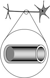
6 . Referring back to our old friend the neuron from the homework problem in chapter 1, let’s now consider what happens when the nerve is stimulated to transmit information. When the blob at the top (the cell body) is stimulated, it causes Na+ ions to rush into the top of the tail (axon). This electrical pulse will then travel down the axon, like a flame burning down from the end of a fuse, with the Na+ ions at each point first going out and then coming back in. If 1010 Na+ ions cross the cell membrane in 0.5 ms, what amount of current is created? Simplify the units of your answer.
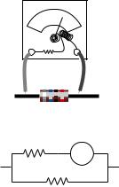
7 . If a typical light bulb draws about 900 mA from a 110-V household circuit, what is its resistance? (Don’t worry about the fact that it’s alternating current.) Simplify the units of your answer.
8 . Today, even a big luxury car like a Cadillac can have an electrical system that is relatively low in power, since it doesn’t need to do much more than run headlights, power windows, etc. In the near future, however, manufacturers plan to start making cars with electrical systems about five times more powerful. This will allow certain energy-wasting parts like the water pump to be run on electrical motors and turned off when they’re not needed — currently they’re run directly on shafts from the motor, so they can’t be shut off. It may even be possible to make an engine that can shut off at a stoplight and then turn back on again without cranking, since the valves can be electrically powered. Current cars’ electrical systems have 12-volt batteries (with 14-volt chargers), but the new systems will have 36-volt batteries (with 42-volt chargers). (a) Suppose the battery in a new car is used to run a device that requires the same amount of power as the corresponding device in the old car. Based on the sample figures above, how would the currents handled by the wires in one of the new cars compare with the currents in the old ones? (b) The real purpose of the greater voltage is to handle devices that need more power. Can you guess why they decided to change to 36-volt batteries rather than increasing the power without increasing the voltage?
9↔. (a ) You take an LP record out of its sleeve, and it acquires a static charge of 1 nC. You play it at the normal speed of 331/3 r.p.m., and the charge moving in a circle creates an electric current. What is the current, in amperes?
(b ) Although the planetary model of the atom can be made to work with any value for the radius of the electrons’ orbits, more advanced models that we will study later in this course predict definite radii. If the electron is imagined as circling around the proton at a speed of 2.2x10⁶ m/s, in an orbit with a radius of 0.05 nm, what electric current is created?
10. We have referred to resistors dissipating heat, i.e. we have assumed that P=I V is always greater than zero. Could I V come out to be negative for a resistor? If so, could one make a refrigerator by hooking up a resistor in such a way that it absorbed heat instead of dissipating it?
Homework Problems |
93 |
Problem 11.
A B
–+
Problem 13.
positive |
negative |
ions |
ions |
Problem 14.
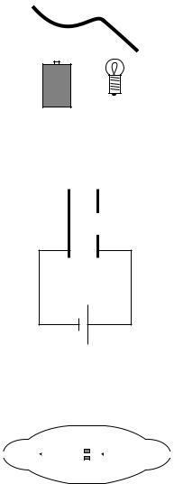
11. You are given a battery, a flashlight bulb, and a single piece of wire. Draw at least two configurations of these items that would result in lighting up the bulb, and at least two that would not light it. (Don’t draw schematics.) If you’re not sure what’s going on, borrow the materials from your instructor and try it. Note that the bulb has two electrical contacts: one is the threaded metal jacket, and the other is the tip. [Problem by Arnold Arons.]
12 S. In a wire carrying a current of 1.0 pA, how long do you have to wait, on the average, for the next electron to pass a given point? Express your answer in units of microseconds.
13 S. The figure shows a simplified diagram of an electron gun such as the one used in the Thomson experiment, or the one that creates the electron beam in a TV tube. Electrons that spontaneously emerge from the negative electrode (cathode) are then accelerated to the positive electrode, which has a hole in it. (Once they emerge through the hole, they will slow down. However, if the two electrodes are fairly close together, this slowing down is a small effect, because the attractive and repulsive forces experienced by the electron tend to cancel.) (a) If the voltage difference between the electrodes is V, what is the velocity of an electron as it emerges at B? (Assume its initial velocity, at A, is negiligible.) (b) Evaluate your expression numerically for the case where V=10 kV, and compare to the speed of light.
14. The figure shows a simplified diagram of a device called a tandem accelerator, used for accelerating beams of ions up to speeds on the order of 1% of the speed of light. The nuclei of these ions collide with the nuclei of atoms in a target, producing nuclear reactions for experiments studying the structure of nuclei. The outer shell of the accelerator is a conductor at zero voltage (i.e. the same voltage as the Earth). The electrode at the center, known as the “terminal,” is at a high positive voltage, perhaps millions of volts. Negative ions with a charge of –1 unit (i.e. atoms with one extra electron) are produced offstage on the right, typically by chemical reactions with cesium, which is a chemical element that has a strong tendency to give away electrons. Relatively weak electric and magnetic forces are used to transport these –1 ions into the accelerator, where they are attracted to the terminal. Although the center of the terminal has a hole in it to let the ions pass through, there is a very thin carbon foil there that they must physically penetrate. Passing through the foil strips off some number of electrons, changing the atom into a positive ion, with a charge of +n times the fundamental charge. Now that the atom is positive, it is repelled by the terminal, and accelerates some more on its way out of the accelerator. (a) Find the velocity, v, of the emerging beam of positive ions, in terms of n, their mass m, the terminal voltage V, and fundamental constants. Neglect the small change in mass caused by the loss of electrons in the stripper foil. (b) To fuse protons with protons, a minimum beam velocity of about 11% of the speed of light is required. What terminal voltage would be needed in this case?
94 |
Chapter 3 Circuits, Part 1 |

4 Circuits, Part 2
In the previous chapter we limited ourselves to relatively simple circuits, essentially nothing more than a battery and a single lightbulb. The purpose of this chapter is to introduce you to more complex circuits, containing multiple resistors or voltage sources in series, in parallel, or both.
Why do you need to know this stuff? After all, if you were planning on being an electrical engineer you probably wouldn’t be learning physics from this book. Consider, however, that every time you plug in a lamp or a radio you are adding a circuit element to a household circuit and making it more complex. Electrical safety, as well, cannot really be understood without understanding multiple-element circuits, since getting shocked usually involves at least two parts: the device that is supposed to use power plus the body of the person in danger. If you are a student majoring in the life sciences, you should realize as well that all cells are inherently electrical, and in any multicellular organism there will therefore be various series and parallel circuits.
Even apart from these practical purposes, there is a very fundamental reason for reading this chapter: to understand the previous chapter better. At this point in their studies, I always observe students using words and modes of reasoning that show they have not yet become completely comfortable and fluent with the concepts of voltage and current. They ask, “aren’t voltage and current sort of the same idea?” They speak of voltage “going through” a lightbulb. Once they begin honing their skills on more complicated circuits I always see their confidence and understanding increase immeasurably.
95

4.1Schematics
I see a chess position; Kasparov sees an interesting Ruy Lopez variation. To the uninitiated a schematic may look as unintelligible as Mayan hieroglyphs, but even a little bit of eye training can go a long way toward making its meaning leap off the page. A schematic is a stylized and simplified drawing of a circuit. The purpose is to eliminate as many irrelevant features as possible, so that the relevant ones are easier to pick out.
An example of an irrelevant feature is the physical shape, length, and diameter of a wire. In nearly all circuits, it is a good approximation to assume that the wires are perfect conductors, so that any piece of wire uninterrupted by other components has constant voltage throughout it. Changing the length of the wire, for instance, does not change this fact. (Of course if we used miles and miles of wire, as in a telephone line, the wire’s resistance would start to add up, and its length would start to matter.) The shapes of the wires are likewise irrelevant, so we draw them with standardized, stylized shapes made only of vertical and horizontal lines with rightangle bends in them. This has the effect of making similar circuits look more alike and helping us to recognize familiar patterns, just as words in a newspaper are easier to recognize than handwritten ones. Figures a-d show some examples of these concepts.
V |
V |
|
V |
|
|
V |
|
(a) wrong: |
(b) wrong: |
(c) wrong: |
(d) right |
Shapes of |
Should |
Makes a simple |
|
wires are |
use right |
pattern look |
|
irrelevant. |
angles. |
unfamliar. |
|
The most important first step in learning to read schematics is to learn to recognize contiguous pieces of wire which must have constant voltage throughout. In figure (e), for example, the two shaded E-shaped pieces of wire must each have constant voltage. This focuses our attention on two of the main unknowns we’d like to be able to predict: the voltage of the left-
hand E and the voltage of the one on the right.
(e)
96 |
Chapter 4 Circuits, Part 2 |
4.2Parallel Resistances and the Junction Rule
(f)R1
R2
(g)
(h)
R1
(i)
R2
One of the simplest examples to analyze is the parallel resistance circuit, of which figure (e) was an example. In general we may have unequal resistances R1 and R2, as in (f). Since there are only two constant-voltage areas in the circuit, (g), all three components have the same voltage difference across them. A battery normally succeeds in maintaining the voltage differences across itself for which it was designed, so the voltage drops V1 and V2 across the resistors must both equal the voltage of the battery:
V1 = V2 = Vbattery .
Each resistance thus feels the same voltage difference as if it was the only one in the circuit, and Ohm’s law tells us that the amount of current flowing through each one is also the same as it would have been in a oneresistor circuit. This is why household electrical circuits are wired in parallel. We want every appliance to work the same, regardless of whether other appliances are plugged in or unplugged, turned on or switched off. (The electric company doesn’t use batteries of course, but our analysis would be the same for any device that maintains a constant voltage.)
Of course the electric company can tell when we turn on every light in the house. How do they know? The answer is that we draw more current. Each resistance draws a certain amount of current, and the amount that has to be supplied is the sum of the two individual currents. The current is like a river that splits in half, (h), and then reunites. The total current is
Itotal |
= I1 + I2 . |
This is an example of a general fact called the junction rule:
the junction rule
In any circuit that is not storing or releasing charge, conservation of charge implies that the total current flowing out of any junction must be the same as the total flowing in.
Coming back to the analysis of our circuit, we apply Ohm’s law to each resistance, resulting in
Itotal |
= |
V/R1 + |
|
V/R2 |
|
||||
|
= |
V |
1 |
|
+ |
|
1 |
|
. |
|
R 1 |
R 2 |
|||||||
|
|
|
|
|
|
||||
As far as the electric company is concerned, your whole house is just one resistor with some resistance R, called the equivalent resistance. They would write Ohm’s law as
Itotal |
= |
V/R , |
from which we can determine the equivalent resistance by comparison with the previous expression:
1 |
= |
1 |
+ |
1 |
|
R |
R 1 |
R 2 |
|||
|
|
Section 4.2 Parallel Resistances and the Junction Rule |
97 |

|
|
1 |
|
1 |
– 1 |
R |
= |
+ |
|
||
R 1 |
R 2 |
|
|||
|
|
|
|
[equivalent resistance of two resistors in parallel]
Two resistors in parallel, (i), are equivalent to a single resistor with a value given by the above equation.
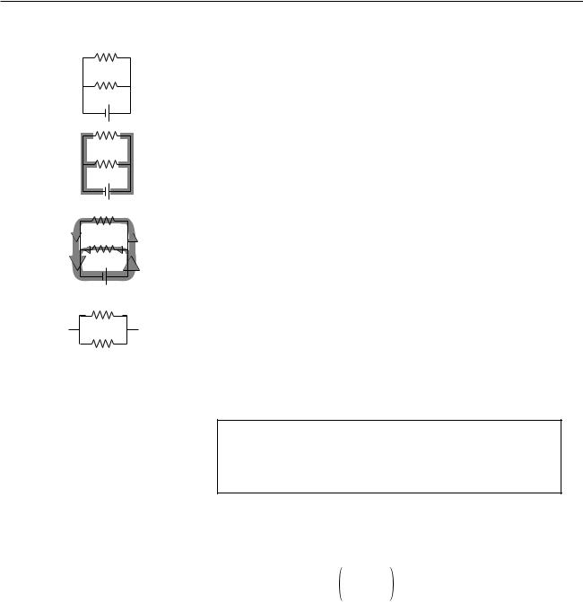
Example: two lamps on the same household circuit
Question: You turn on two lamps that are on the same household circuit. Each one has a resistance of 1 ohm. What is the equivalent resistance, and how does the power dissipation compare with the case of a single lamp?
Solution: The equivalent resistance of the two lamps in parallel is
R |
= |
|
|
1 |
+ |
1 |
|
– 1 |
|||
|
R2 |
|
|
|
|||||||
|
|
|
|
R1 |
|
|
|
||||
|
|
1 |
|
|
1 |
|
– 1 |
||||
|
|
|
|
|
|
||||||
|
= |
|
|
|
+ |
|
|
|
|||
|
|
|
1 Ω |
1 |
Ω |
||||||
|
= (1 Ω –1 + 1 Ω –1)–1 |
||||||||||
|
= |
(2 Ω –1) –1 |
|
|
|
||||||
|
= |
0.5 Ω |
|
|
|
|
|
||||
The voltage difference across the whole circuit is always the 110 V set by the electric company (it’s alternating current, but that’s irrelevant). The resistance of the whole circuit has been cut in half by turning on the second lamp, so a fixed amount of voltage will produce twice as much current. Twice the current flowing across the same voltage difference means twice as much power dissipation, which makes sense.
The cutting in half of the resistance surprises many students, since we are “adding more resistance” to the circuit by putting in the second lamp. Why does the equivalent resistance come out to be less than the resistance of a single lamp? This is a case where purely verbal reasoning can be misleading. A resistive circuit element, such as the filament of a lightbulb, is neither a perfect insulator nor a perfect conductor. Instead of analyzing this type of circuit in terms of “resistors,” i.e. partial insulators, we could have spoken of “conductors.” This example would then seem reasonable, since we “added more conductance,” but one would then have the incorrect expectation about the case of resistors in series, discussed in the following section.
Perhaps a more productive way of thinking about it is to use mechanical intuition. By analogy, your nostrils resist the flow of air through them, but having two nostrils makes it twice as easy to breathe.
98 |
Chapter 4 Circuits, Part 2 |
R1
(a)
R2
R3
R1
(b)
R2
R3
R1 and 2
(c)
R3
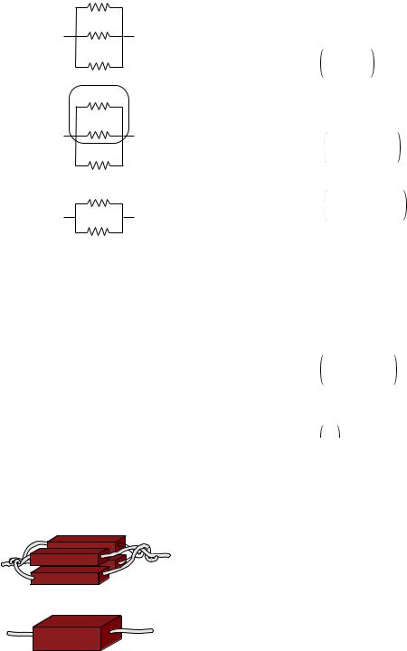
Uniting four resistors in parallel is equivalent to making a single resistor with the same length but four times the cross-sectional area. The result is to make a resistor with one quarter the resistance.
Example: three resistors in parallel
Question: What happens if we have three or more resistors in parallel?
Solution: This is an important example, because the solution involves an important technique for understanding circuits: breaking them down into smaller parts and them simplifying those parts. In the circuit (a), with three resistors in parallel, we can think of two of the resistors as forming a single big resistor, (b), with equivalent resistance
R |
|
= |
1 |
+ |
1 |
– 1 . |
|
R1 |
|
||||
|
1 and 2 |
|
|
R2 |
||
|
|
|
|
|
|
|
We can then simplify the circuit as shown in (c), so that it contains only two resistances. The equivalent resistance of the whole circuit is then given by
R |
|
= |
1 |
+ |
1 |
– 1 . |
1, 2 and 3 |
|
|
||||
|
|
R1 and 2 |
|
R3 |
||
|
|
|
|
|||
Substituting for R1 and 2 and simplifying, we find the result
R |
|
= |
1 |
+ |
1 |
+ |
1 |
– 1 |
, |
|
R1 |
R2 |
|
||||||
|
1, 2 and 3 |
|
|
|
R3 |
|
|||
|
|
|
|
|
|
|
|
|
|
which you probably could have guessed. The interesting point here is the divide-and-conquer concept, not the mathematical result.
Example: an arbitrary number of identical resistors in parallel
Question: What is the resistance of N identical resistors in parallel?
Solution: Generalizing the results for two and three resistors, we have
|
|
|
1 |
+ |
1 |
+ ... |
– 1 |
R |
|
= |
, |
||||
|
R1 |
|
|||||
|
N |
|
|
R2 |
|
||
|
|
|
|
|
|
|
|
where “...” means that the sum includes all the resistors. If all the resistors are identical, this becomes
N – 1
RN =  R
R 
=R N
Example: dependence of resistance on cross-sectional area
We have alluded briefly to the fact that an object’s electrical resistance depends on its size and shape, but now we are ready to begin making more mathematical statements about it. As suggested by the figure, increasing a resistors’s cross-sectional area is equivalent to adding more resistors in parallel, which will lead to an overall decrease in resistance. Any real resistor with straight, parallel sides can be sliced up into a large number of pieces, each with cross-sectional area of, say, 1 μm2. The number, N, of such slices is proportional to the total crosssectional area of the resistor, and by application of the result of the previous example we therefore find that the resistance of an object is inversely proportional to its cross-sectional area.
An analogous relationship holds for water pipes, which is why high-flow trunk lines have to have large cross-sectional areas. To make lots of water (current) flow through a skinny pipe, we’d need an impractically large pressure (voltage) difference.
Section 4.2 Parallel Resistances and the Junction Rule |
99 |
(a)
(b)Rv
A
R
A voltmeter is really an ammeter with an internal resistor. When we measure the voltage difference across a resistor, (a), we are really constructing a parallel resistance circuit, (b).
Example: incorrect readings from a voltmeter
A voltmeter is really just an ammeter with an internal resistor, and we use a voltmeter in parallel with the thing that we’re trying to measure the voltage difference across. This means that any time we measure the voltage drop across a resistor, we’re essentially putting two resistors in parallel. The ammeter inside the voltmeter can be ignored for the purpose of analyzing what how current flows in the circuit, since it is essentially just some coiled-up wire with a very low resistance.
Now if we are carrying out this measurement on a resistor that is part of a larger circuit, we have changed the behavior of the circuit through our act of measuring. It is as though we had modified the circuit by replacing the resistance R with the smaller equivalent resistance of R and Rv in parallel. It is for this reason that voltmeters are built with the largest possible internal resistance. As a numerical example, if we use a voltmeter with an internal resistance of 1 MΩ to measure the voltage drop across a one-ohm resistor, the equivalent resistance is 0.999999 Ω, which is not different enough to matter. But if we tried to use the same voltmeter to measure the voltage drop across a 2-MΩ resistor, we would be reducing the resistance of that part of the circuit by a factor of three, which would produce a drastic change in the behavior of the whole circuit.
This is the reason why you can’t use a voltmeter to measure the voltage difference between two different points in mid-air, or between the ends of a piece of wood. This is by no means a stupid thing to want to do, since the world around us is not a constant-voltage environment, the most extreme example being when an electrical storm is brewing. But it will not work with an ordinary voltmeter because the resistance of the air or the wood is many gigaohms. The effect of waving a pair of voltmeter probes around in the air is that we provide a reuniting path for the positive and negative charges that have been separated — through the voltmeter itself, which is a good conductor compared to the air. This reduces to zero the voltage difference we were trying to measure.
In general, a voltmeter that has been set up with an open circuit (or a very large resistance) between its probes is said to be “floating.” An old-fashioned analog voltmeter of the type described here will read zero when left floating, the same as when it was sitting on the shelf. A floating digital voltmeter usually shows an error message.
100 |
Chapter 4 Circuits, Part 2 |