


SECTION 12 – ANNUNCIATIONS
&ALERTS
12.3G1000 SYSTEM ANNUNCIATIONS
WhenanLRUoranLRUfunctionfails,alargered‘X’is typically displayed on windows associated with the failed data. The following section describes various system annunciations. Refer to the POH for additional information regarding pilot responses to these annunciations.
System Annunciation |
Comment |
Attitude and Heading Reference System is aligning.
Display system is not receiving attitude information from theAHRS.
Display system is not receiving airspeed input from air data computer.
NOTE: Upon power-up of the G1000 system, certain windows remain invalid as G1000 equipment begins to initialize. All windows should be operational within one minute of power-up. Should any window continue to remain flagged, the G1000 system should be serviced by a Garmin-authorized repair facility.
12-4 |
Garmin G1000 Cockpit Reference Guide for the Cessna Nav III |
SECTION 12 – ANNUNCIATIONS
& ALERTS
System Annunciation |
Comment |
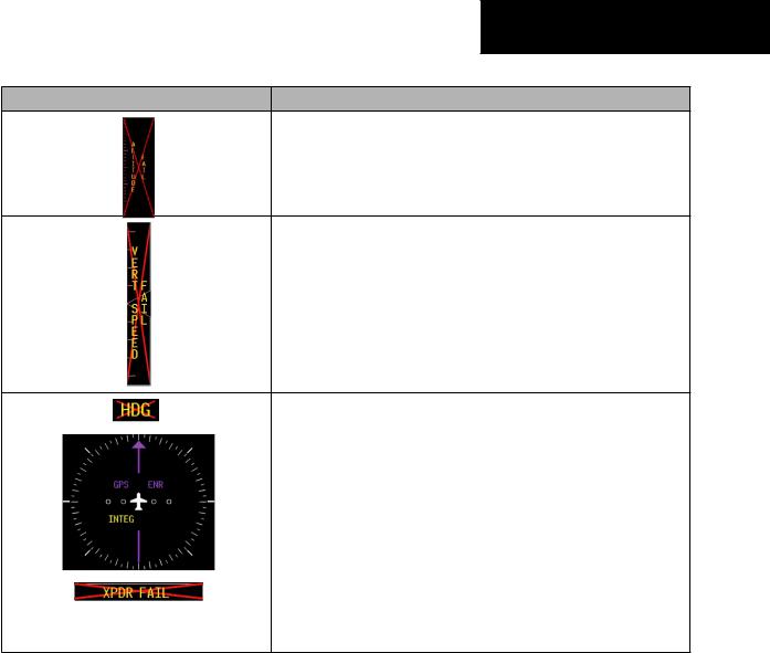
Display is not receiving altitude input from the air data computer.
Display is not receiving vertical speed input from the air data computer.
|
Display is not receiving valid heading input fromAHRS. |
|
|
|
|
|
GPS information is either not present or is invalid for navigation use. |
|
|
Note thatAHRS utilizes GPS inputs during normal operation. AHRS opera- |
|
|
tion may be degraded if GPS signals are not present (seeAFMS). |
|
|
|
|
|
Display is not receiving valid transponder information. |
|
|
|
|
OtherVarious Red X Indications |
A red ‘X’ through any other display field, such as engine instrumentation |
|
fields, indicates that the field is not receiving valid data. |
||
|
Garmin G1000 Cockpit Reference Guide for the Cessna Nav III |
12-5 |

SECTION 12 – ANNUNCIATIONS
& ALERTS
A red ‘X’ may be the result of an LRU or an LRU func- |
|
|
tion failure. The Figure 12-5 illustrates all possible flags |
NOTE: This Section provides information regard- |
|
and the responsible LRUs. |
ing G1000 message advisories that may be dis- |
|
12.4 G1000 SYSTEM MESSAGE |
played by the system. Knowledge of the aircraft, |
|
systems, flight conditions, and other existing |
||
ADVISORIES |
operational priorities must be considered when |
|
responding to a message. Always use sound pilot |
||
|
||
This section describes various G1000 system message |
judgment. The Cessna aircraft Pilot’s Operating |
|
advisories. CertainmessagesareissuedduetoanLRUoran |
Handbook (POH) takes precedence over any |
|
conflicting guidance found in this section. |
||
LRU function failure. Such messages are normally accom- |
||
|
||
panied by a corresponding red ‘X’ annunciation as shown |
|
|
previously in the G1000 System Annunciation section. |
|
GIA 63 Integrated |
|
|
|
|
|
|
|
|
|
|
|
GIA 63 Integrated |
||||||
|
|
|
|
|
|
|
|
|||||||||||
Avionics Units |
|
|
|
|
Avionics Units |
|||||||||||||
|
|
|
|
|
|
|
|
|
|
|
|
|
|
|
|
|
|
GDC 74A Air Data |
|
|
|
|
|
|
|
|
|
|
|
|
|
|
|
|
|
|
|
|
|
|
|
|
|
|
|
|
|
|
|
|
|
|
|
|
|
|
|
|
|
|
|
|
|
|
|
|
|
|
|
|
|
|
|
|
Computer |
|
|
|
|
|
|
|
|
|
|
|
|
|
|
|
|
|
|
GRS 77 AHRS |
|
|
|
|
|
|
|
|
|
|
|
|
|
|
|
|
|
|
|
|
|
|
|
|
|
|
|
|
|
|
|
|
|
|
|
|
|
|
|
|
|
|
|
|
|
|
|
|
|
|
|
|
|
|
|
|
|
GEA 71 Engine |
|
|
|
|
|
|
|
|
|
|
|
OR |
||||||
|
|
|
|
|
|
|
|
|
|
|
|
|
|
|
|
|||
Airframe Unit |
|
|
|
|
|
|
|
|
|
|
GMU 44 |
|||||||
OR |
|
|
|
|
|
|
|
|
|
|
Magnetometer |
|||||||
GIA 63 Integrated |
|
|
|
|
|
|
|
|
|
|
|
|||||||
Avionics Unit |
|
|
|
|
|
|
|
|
|
|
|
|
GIA 63 Integrated |
|||||
|
|
|
|
|
|
|
|
|
|
|
|
|
|
|
|
|
|
|
|
|
|
|
|
|
|
|
|
|
|
|
|
|
|
|
|
|
|
|
|
|
|
|
|
|
|
|
|
|
|
|
|
|
|
|
|
Avionics Units |
|
|
|
|
|
|
|
|
|
|
|
|
|
|
|
|
|
|
GTX 33 Transponder |
|
|
|
|
|
|
|
|
|
|
|
|
|
|
|
|
|
|
|
|
|
|
|
GDC 74A Air Data |
|
|
|
|
|
|
|
|
|
|||||
|
|
|
|
|
|
|
|
|
|
|
|
|
||||||
|
|
|
|
|
|
|
|
|
|
|
|
|
OR |
|||||
|
|
|
|
Computer |
|
|
|
|
||||||||||
|
|
|
|
|
|
|
|
GIA 63 Integrated |
||||||||||
|
|
|
|
|
|
|
|
Figure 12-5 G1000 System Failure Annunciations |
|
|
|
|
||||||
|
|
|
|
|
|
|
|
|
|
|
|
Avionics Units |
||||||
12-6 |
Garmin G1000 Cockpit Reference Guide for the Cessna Nav III |
|
|
SECTION 12 – ANNUNCIATIONS |
|
|
|
& ALERTS |
|
MFD & PFD Message Advisories |
|
|
|
|
|
|
|
|
|
|
|
Message |
Comments |
|
|
DATA LOST – Pilot stored data was |
The pilot profile data was lost. System reverts to default pilot profile and settings. |
|
|
lost. Recheck settings. |
The pilot may reconfigure the MFD & PFD with preferred settings, if desired. |
|
|
XTALK ERROR –A flight display |
The MFD and PFD are not communicating with each other. The G1000 system should |
|
|
crosstalk error has occurred. |
be serviced. |
|
|
PFD1 SERVICE – PFD1 needs service. |
|
|
|
Return unit for repair. |
The PFD and/or MFD self-test has detected a problem. The G1000 system should be |
|
|
MFD1 SERVICE – MFD1 needs |
serviced. |
|
|
service. Return unit for repair. |
|
|
|
PFD1 CONFIG – PFD1 configuration |
|
|
|
error. Config service required. |
The PFD and/or MFD configuration settings do not match backup configuration |
|
|
MFD1 CONFIG – MFD1 configuration |
memory. The G1000 system should be serviced. |
|
|
error. Config service required. |
|
|
|
SW MISMATCH – GDU software |
The MFD and PFD have different software versions installed. The G1000 system |
|
|
mismatch. Xtalk is off. |
should be serviced. |
|
|
MANIFEST – PFD1 software mismatch. |
|
|
|
Communication halted. |
The PFD and/or MFD has incorrect software installed. The G1000 system should be |
|
|
MANIFEST – MFD1 software |
serviced. |
|
|
mismatch. Communication halted. |
|
|
|
PFD1 COOLING – PFD1 has poor |
|
|
|
cooling. Reducing power usage. |
The PFD and/or MFD is overheating and is reducing power consumption by dimming |
|
|
MFD1 COOLING – MFD1 has poor |
the display. If problem persists, the G1000 system should be serviced. |
|
|
cooling. Reducing power usage. |
|
|
|
PFD1 “KEY” KEYSTK – Key is stuck. |
A key is stuck on the PFD and/or MFD bezel. Attempt to free the stuck key by press- |
|
|
MFD1 “KEY” KEYSTK – Key is stuck. |
ing it several times. The G1000 system should be serviced if the problem persists. |
|
|
CNFG MODULE – PFD1 configuration |
The PFD configuration module backup memory has failed. The G1000 system should |
|
|
module is inoperative. |
be serviced. |
|
|
Garmin G1000 Cockpit Reference Guide for the Cessna Nav III |
12-7 |