

8E - 66 INSTRUMENT PANEL AND GAUGES |
|
Ä |
|
Fig. 20 Turbo Gauge and Message Center Module
SWITCH AND PANEL COMPONENT SERVICE
LOWER STEERING COLUMN COVER REPLACEMENT
(1)Disconnect park brake release rod from the park brake handle.
(2)Remove two screws attaching hood release (Fig.
21).
(3)Remove fuse access door and remove steering column cover attaching screw located directly above the fuse block.
(4)Remove six screws around outside of steering column cover.
(5)Remove steering column cover.
(6)For installation reverse above procedures.
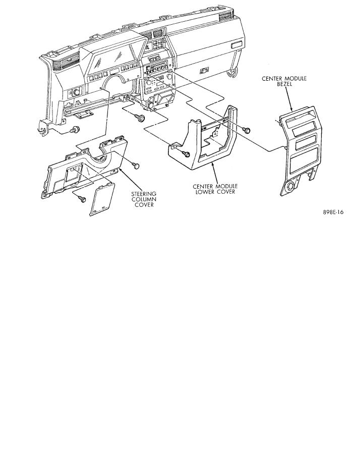
CENTER MODULE LOWER COVER
REPLACEMENT
(1)Open ash receiver and remove center module
bezel.
(2)Remove module cover to instrument panel retaining screws (Fig. 21).
(3)Remove module cover from vehicle.
(4)For installation reverse above procedures.
CENTER MODULE BEZEL REPLACEMENT
(1)Open ash receiver.
(2)Grip module bezel around outer edges and pull rearward to release six spring-type retaining clips (Fig. 21).
(3)For installation position spring clips to instrument panel and push firmly until seated.
(4)Close ash receiver.
Fig. 21 Lower Instrument Panel

Ä |
|
INSTRUMENT PANEL AND GAUGES 8E - 67 |
|
HEADLAMP SWITCH REPLACEMENT
(1) Snap headlamp switch bezel out of instrument panel pad (Fig. 22).
Fig. 22 Headlamp Switch Assembly
(2)Remove three screws securing headlamp switch mounting plate to instrument panel.
(3)Pull headlamp switch and mounting plate rearward from instrument panel opening.
(4)Disconnect wiring connector from switch.
(5)Remove switch knob by depressing release button on switch and pulling knob out from switch.
(6)Snap headlamp switch escutcheon out of mounting plate to gain access to mounting plate retaining nut.
(7)Remove headlamp switch to mounting plate retaining nut and separate switch from mounting plate.
(8)For installation reverse above procedures.
A/C HEATER CONTROL REPLACEMENT
(1)Remove center bezel assembly.
(2)Remove A/C control to instrument panel retaining screws (Fig. 23).
(3)Pull control rearward and disconnect temperature control cable and electrical and vacuum connectors.
(4)Remove control from vehicle.
(5)For installation reverse above procedures.
HEATER CONTROL LAMP REPLACEMENT
(1)Remove heater control. Refer to A/C Heater Control for removal.
(2)Pull control far enough to gain access to the lamp socket.
Fig. 23 A/C Heater Control
(3)Replace lamp. To remove lamp rotate socket counter clockwise. To install rotate clockwise.
(4)For installation reverse above procedures.
A/C CONTROL LAMP REPLACEMENT
(1)Remove heater control. Refer to A/C Heater Control for removal.
(2)Pry temperature and blower switch knobs off with flat blade tool. To protect cosmetic face place cardboard or similar material on the face plate while prying.
(3)Remove face plate by lifting on the six tabs. Three on top and three on bottom of the face plate.
(4)Replace lamp.
(5)For installation reverse above procedures.
HEATER CONTROL BLOWER SWITCH REPLACEMENT
(1)Remove heater control. Refer to A/C Heater Control for removal.
(2)Pry temperature and blower switch knobs off with flat blade tool. To protect cosmetic face place cardboard or similar material on the face plate while prying.
(3)Remove face plate by lifting on the six tabs. Three on top and three on bottom of the face plate.
(4)Pry blower switch off with flat blade tool. To protect cosmetic face, place cardboard or similar material on the face plate while prying.
(5)To replace, line up blower switch terminals and press firmly until the it bottoms out on the housing.
(6)For installation reverse above procedures.
A/C CONTROL BLOWER SWITCH
REPLACEMENT
(1)Remove heater control. Refer to A/C Heater Control for removal.
(2)Position the temperature knob at the maximum heat position to gain screw access.
(3)Remove two screws holding the blower switch located on top of the control.
(4)Pry the blower switch off with a flat blade tool.
(5)To replace, line up blower switch terminals and press firmly until the it bottoms out on the housing.
(6)For installation reverse above procedures.
8E - 68 INSTRUMENT PANEL AND GAUGES
GLOVE BOX MODULE REPLACEMENT
(1) Open glove box door (Fig. 24).
Fig. 24 Glove Box, Ash Receiver and Cigar Lighter
(2)Remove check strap screws to allow full downward movement of the glove box door.
(3)Remove six screws attaching glove box module to instrument panel.
(4)Pull glove box module rearward and disconnect wiring from lamp and switch.
(5)Remove glove box from vehicle.
(6)For installation reverse above procedures. When installing glove box module, be sure that left edge of module is pressed against foam bead on trim pad. This will assure that there will be an adequate gap between right edge of glove box door and trim pad.
ASH RECEIVER ASSEMBLY REPLACEMENT
(1)Open ash receiver and remove center module
bezel.
(2)Remove ash receiver bracket to instrument panel retaining screws (Fig. 24).
(3)Pull assembly rearward off of locating pins and disconnect wiring for lamp.
(4)Remove ash receiver from vehicle.
(5)For installation reverse above procedures.
CIGAR LIGHTER REPLACEMENT
(1)Remove center bezel assembly (Fig. 24).
(2)Remove center module lower cover or open forward console lid.
(3)Unscrew lighter receptacle shell from receptacle and remove from base instrument panel.
(4)Disconnect wiring connectors from lighter receptacle and remove from vehicle.
(5)For installation reverse above procedures.
Ä
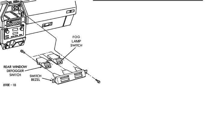
REAR WINDOW DEFOGGER AND FOG LAMP SWITCH REPLACEMENT
(1) Remove center bezel assembly (Fig. 25).
Fig. 25 Rear Window Defogger and Fog Lamp
Switch
(2)Remove two defogger switch bezel screws.
(3)Pull switch and bezel rearward and disconnect wiring connector.
(4)Remove two defogger switch retaining screws.
(5)Remove switch from bezel.
(6)For installation reverse above procedures.
INTERMITTENT WIPE MODULE
REPLACEMENT
(1)Remove lower steering column cover.
(2)Slide intermittent wipe module off of bracket located on steering column reinforcement (Fig. 26).
(3)Disconnect wiring connector from module and remove module from vehicle.
(4)For installation reverse above procedures.
GLOVE BOX LAMP AND SWITCH
REPLACEMENT
(1)Open glove box door (Fig. 27).
(2)Carefully pry lamp from its mounting surface with tip of a small screwdriver.
(3)Pull lamp from box and disconnect electrical leads.
(4)Remove lamp.
(5)For installation reverse above procedures.
CONSOLETTE ASSEMBLY REPLACEMENT
(1)Remove shifter handle.
(2)Unsnap PRNDL bezel or shift boot bezel from consolette, disconnect wiring and remove bezel assembly (Fig. 28).
(3)Remove two screws from side of armrest.