


8E - 2 INSTRUMENT PANEL AND GAUGES |
|
Ä |
|
Fig. 3 Message Center
shield washer fluid, door ajar 1 for each door, and trunk ajar. It also includes headlamp out, tail lamp out, and brake lamp out warning lights (Fig. 3), these lights are operated by a lamp outage module.
TRAVELER
The traveler is a five function trip computer. It uses vacuum fluorescent displays to display: trip miles, instantaneous fuel economy, trip elapsed time, trip average fuel economy and, estimate distance to empty. It is located in the instrument cluster with the message center (Fig. 4).
Fig. 4 Traveler and Message Center
WARNING LAMPS AND INDICATOR LIGHTS
The mechanical instrument cluster assemblies have warning lamps and indicator lights for ten different systems. These include left and right turn signals, low fuel level, low oil pressure, high beam indicator,
seat belt reminder, brake system, check engine, check gauges, anti-lock system and air bag system indicator.
The low oil pressure indicator replaces the Check Gauges indicator in the cluster assembly without a tachometer.
In the cluster assembly with tachometer, Check Gauges indictor illuminates in a warning situation. This will notify driver to check for a problem in coolant temperature, oil pressure or electrical systems.
CLUSTER AND GAUGE SERVICE AND TESTING
CAUTION: Disconnect battery cable. Before servicing the instrument panel. Reconnect battery cable when power is required for test purposes.
Disconnect battery cable after test and before continuing service procedures.
SENDING UNIT TEST
When a problem occurs with a cluster gauge, before disassembling the cluster to check the gauge, check for a defective sending unit or wiring.
(1) Sending units and wiring can be checked by grounding the connector leads, at the sending unit, in the vehicle.

Ä |
|
INSTRUMENT PANEL AND GAUGES 8E - 3 |
|
(2) With the ignition in the ON position; a grounded input will cause the oil, fuel or temperature gauge to read at or above maximum.
LOW OIL PRESSURE/CHECK GAUGES WARNING LAMP TEST
The low oil pressure/check gauges warning lamp will illuminate when the ignition key is turned to the ON position without starting the vehicle.
In the cluster assembly without tachometer, the low oil pressure lamp will illuminate if the engine oil pressure drops below a safe oil pressure level.
In the cluster assembly with tachometer, the Check Gauges warning lamp illuminates when there is a problem in oil pressure level, high engine temperature or low voltage.
To test the system turn ignition key to the ON position. If the lamp fails to light, inspect for a broken or disconnected wire at the oil pressure combination unit, which is located at the front of the engine (Figs. 5 and 6). If the wire at the connector checks good, pull connector loose from the switch terminal and with a jumper wire ground connector to the engine (Fig. 7). With the ignition key turned to the ON position check the warning lamp. If lamp still fails to light, inspect for a burned out lamp or disconnected socket in the cluster.
Fig. 5 Combination Oil Unit (2.5L)
COMBINATION OIL UNIT TEST
The combination oil unit has two functions:
(1)The normal closed circuit keeps the oil pressure warning/check gauges lamp on until there is oil pressure (Fig. 7).
(2)The sending unit provides a resistance that varies with oil pressure.
(3)To test the normally closed oil lamp circuit, disconnect the locking connector and measure the resistance between the switch terminal and the metal housing. The ohmmeter should read 0 ohms. Start the engine.
Fig. 6 Combination Oil Unit (3.0L)
Fig. 7 Combination Oil Unit Test
(4)If there is oil pressure, the ohmmeter should read an open circuit.
(5)To test the sending unit, measure the resistance between the sending unit terminal and the metal housing. The ohmmeter should read open. Start the engine.
(6)The ohmmeter should read between 30 to 55 ohms, depending on engine speed, oil temperature, and oil viscosity.
(7)If the above results are not obtained, replace the switch.
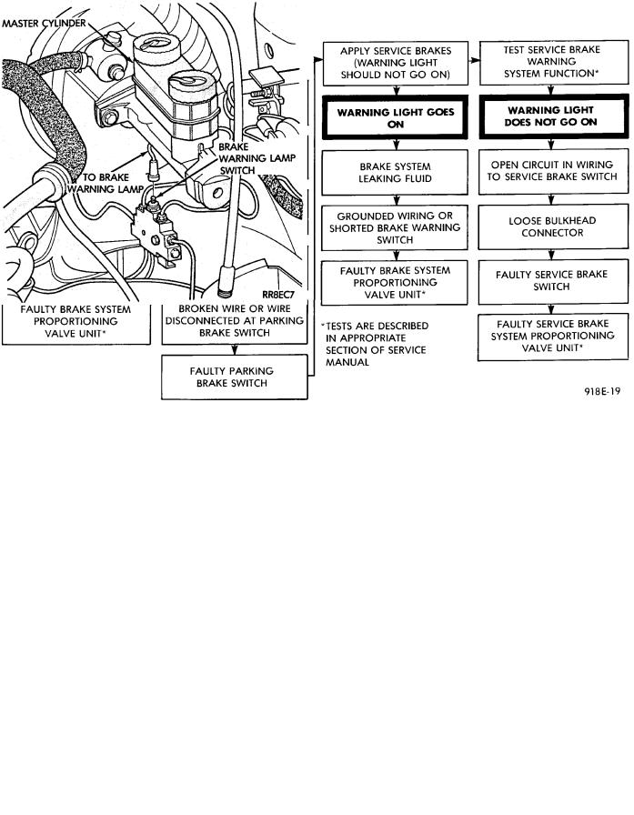
BRAKE SYSTEM WARNING LAMP TEST
The brake warning lamp illuminates when parking brake is applied with ignition key turned ON. The same lamp will also illuminate should one of the two service brake systems fail when brake pedal is applied. To test system turn ignition key ON, and apply parking brake. If lamp fails to light, inspect for a burned out lamp, disconnected socket, a broken or disconnected wire at switch. The lamp also lights when the ignition switch is turned to START.
To test service brake warning system, raise vehicle on a hoist and open a wheel cylinder bleeder while a helper depresses brake pedal and observes warning
8E - 4 INSTRUMENT PANEL AND GAUGES |
|
Ä |
|
lamp. If lamp fails to light, inspect for a burned out lamp, disconnected socket, a broken or disconnected wire at switch.
If lamp is not burned out and wire continuity is proven, replace brake warning switch in brake line Tee fitting mounted on frame rail in engine compartment below master cylinder (Fig. 8 and 9).
CAUTION: If wheel cylinder bleeder was opened check master cylinder fluid level.
SEAT BELT WARNING SYSTEM
For testing of this system refer to Group 8M, Restraint Systems.
CHECK ENGINE SYSTEM
For testing this system refer to the Powertrain Diagnostic Test Procedures booklet.
AIR BAG WARNING SYSTEM
For testing this system refer to Group 8M, Restraint Systems.
MECHANICAL/ELECTRONIC CLUSTER REMOVAL
CLUSTER BEZEL REMOVAL
(1) On column shift vehicles, place column shifter to neutral position.
Fig. 8 Brake Warning Lamp Switch
(2)On tilt steering column vehicles, adjust tilt range to lowest position.
(3)Pull cluster bezel rearward to disengage 11 clips (Fig. 10).
Fig. 9 Brake System Warning Lamp Diagnosis

Ä |
|
INSTRUMENT PANEL AND GAUGES 8E - 5 |
|
Fig. 10 Cluster Bezel
(4)Remove cluster bezel.
(5)For installation reverse above procedures.
CLUSTER MASK AND LENS REMOVAL
(1)Remove cluster, radio and rear window defogger bezels (Fig. 10).
(2)Remove four cluster to panel screws.
(3)Pull cluster assembly rearward. Vehicles with column shift use care to not damage PRNDL guide tube.
(4)Remove four screws holding the cluster mask to cluster housing (Fig. 11).
Fig. 11 Cluster Mask and Lens
(5)Pull cluster mask and lens rearward to remove.
(6)For installation reverse above procedures.
CLUSTER ASSEMBLY
REMOVALÐCLUSTER WITH PRNDL FROM STEERING COLUMN
(1)Disconnect battery to assure no air bag system fault codes are stored.
(2)Remove cluster bezel (Fig. 10).
(3)On column shift vehicle: (Fig. 12 through 15).
(a)Remove lower steering column cover (Fig. 16). Release guide tube from behind fuse block.
(b)Place gear shift lever in neutral or park.
(c)Remove guide tube from behind fuse block and disconnect cable eyelet from column actuating arm.
Fig. 12 PRNDL Step 1
Fig. 13 PRNDL Step 2
(d)Release lock bar on column insert, squeeze legs together and remove from column (Fig. 14).
(e)Secure insert and cable guide out of the way.
(4)Remove the rear window defogger bezel and radio bezel.
(5)Remove the upper steering column cover.
(6)Remove the four screws attaching cluster housing to the base panel.
(7)Pull cluster rearward, reach behind cluster and disconnect the two wiring harnesses.
(8)Remove cluster assembly.

8E - 6 INSTRUMENT PANEL AND GAUGES |
|
Ä |
|
Fig. 14 PRNDL Step 3 |
Fig. 15 PRNDL Step 4 |
Fig. 16 Instrument Panel Bezels
INSTALLATION
(1)Connect wiring harnesses.
(2)Position cluster and secure to base panel with four screws.
(3)On column shift vehicles (Fig. 12 through 15):
(a)Route PRNDL guide assembly under left steering column wing and down left side of column (Fig. 12).
(b)Insert flange of column insert into column, squeeze legs together with tabs under column jacket and engage lock bar to secure insert (Fig. 14).
(c)Hook cable eyelet to steering column actuator check pointer, should indicate neutral. Do not kink or bind PRNDL guide tube and position guide tube in original location.
(d)Adjust with tool if necessary to center pointer on N (Neutral) and check in other gears (Fig. 15).