
Ä |
|
HORNS 8G - 1 |
|
HORNS
CONTENTS
|
page |
GENERAL INFORMATION . . . . . . . . . . . . . . . . |
. . 1 |
HORN SWITCH REPLACEMENT . . . . . . . . . . . |
. . 2 |
GENERAL INFORMATION
WARNING: ON VEHICLES EQUIPPED WITH AIRBAG, SEE GROUP 8M, RESTRAINT SYSTEMS FOR STEERING WHEEL OR COLUMN REMOVAL PROCEDURES.
The horn circuit consists of a horn switch, horn relay, and horns. The horn circuit feed is from the fuse box to the number 1 terminal on the horn relay. When the horn switch is depressed, it completes the ground circuit. Then the horn relay coil, closing a set of contacts in the relay allowing current to flow to the horns. The horn is grounded to the headlamp ground (Fig. 1).
Fig. 1 Conventional Horn System
TESTING HORN SYSTEM
HORNS WILL NOT SOUND
If the horns do not sound, check for a blown horn fuse in the fuse block. If the fuse is blown, replace it with the same fuse type. If the horns fail to sound and the new fuse blows when depressing the horn switch, a short circuit in the horn or the horn wiring between the fuse terminal and the horn is responsible.
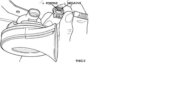
If the fuse is intact, disconnect wire connector at horn and connect one lead of a test lamp to the positive wire terminal and the other lead to ground wire terminal (Fig. 2). Depress the horn switch, the test lamp should illuminate. If not connect the test lamp wire to a good ground and depress the horn switch. If test lamp lights inspect ground wire circuit and repair as needed.
page
TESTING HORN SYSTEM . . . . . . . . . . . . . . . . . . |
1 |
Fig. 2 Horn and Connector
If the test lamp fails to illuminate, check for a defective horn relay. Substituting a known good horn relay in the circuit. If the test lamp illuminates when depressing the horn switch, the original relay is defective. If the test lamp fails to illuminate with a known good relay, unplug that relay. Connect a jumper wire from the battery terminal to the horn terminal on the relay terminal board (Fig. 3, 4, or 5). If the test lamp connected in place of the horns, fails to illuminate an open circuit in the wiring between the relay terminal and the horn switch is at fault repair as necessary.
HORNS SOUND CONTINUOUSLY
CAUTION: Continuous sounding of horns may cause relay to fail.
Should the horns sound continuously, unplug the horn relay from the terminal board inside the passenger compartment. Plug in a known good relay. If the horns stop blowing, relay is defective and must be replaced. Should the horns still sound, proceed as follows: Connect one voltmeter lead to battery terminal on relay board and the other lead to switch terminal. Refer to Figs. 6, 7, or 8. Voltmeter will register battery voltage when the wire to the horn switch is shorted to ground or the horn switch is defective.
