

- •Table of Contents
- •About the Author
- •About the Technical Reviewer
- •Acknowledgments
- •Software Entropy
- •Clean Code
- •C++11: The Beginning of a New Era
- •Who This Book Is For
- •Conventions Used in This Book
- •Sidebars
- •Notes, Tips, and Warnings
- •Code Samples
- •Coding Style
- •C++ Core Guidelines
- •Companion Website and Source Code Repository
- •UML Diagrams
- •The Need for Testing
- •Unit Tests
- •What About QA?
- •Rules for Good Unit Tests
- •Test Code Quality
- •Unit Test Naming
- •Unit Test Independence
- •One Assertion per Test
- •Independent Initialization of Unit Test Environments
- •Exclude Getters and Setters
- •Exclude Third-Party Code
- •Exclude External Systems
- •What Do We Do with the Database?
- •Don’t Mix Test Code with Production Code
- •Tests Must Run Fast
- •How Do You Find a Test’s Input Data?
- •Equivalence Partitioning
- •Boundary Value Analysis
- •Test Doubles (Fake Objects)
- •What Is a Principle?
- •KISS
- •YAGNI
- •It’s About Knowledge!
- •Building Abstractions Is Sometimes Hard
- •Information Hiding
- •Strong Cohesion
- •Loose Coupling
- •Be Careful with Optimizations
- •Principle of Least Astonishment (PLA)
- •The Boy Scout Rule
- •Collective Code Ownership
- •Good Names
- •Names Should Be Self-Explanatory
- •Use Names from the Domain
- •Choose Names at an Appropriate Level of Abstraction
- •Avoid Redundancy When Choosing a Name
- •Avoid Cryptic Abbreviations
- •Avoid Hungarian Notation and Prefixes
- •Avoid Using the Same Name for Different Purposes
- •Comments
- •Let the Code Tell the Story
- •Do Not Comment Obvious Things
- •Don’t Disable Code with Comments
- •Don’t Write Block Comments
- •Don’t Use Comments to Substitute Version Control
- •The Rare Cases Where Comments Are Useful
- •Documentation Generation from Source Code
- •Functions
- •One Thing, No More!
- •Let Them Be Small
- •“But the Call Time Overhead!”
- •Function Naming
- •Use Intention-Revealing Names
- •Parameters and Return Values
- •Avoid Flag Parameters
- •Avoid Output Parameters
- •Don’t Pass or Return 0 (NULL, nullptr)
- •Strategies for Avoiding Regular Pointers
- •Choose simple object construction on the stack instead of on the heap
- •In a function’s argument list, use (const) references instead of pointers
- •If it is inevitable to deal with a pointer to a resource, use a smart one
- •If an API returns a raw pointer...
- •The Power of const Correctness
- •About Old C-Style in C++ Projects
- •Choose C++ Strings and Streams over Old C-Style char*
- •Use C++ Casts Instead of Old C-Style Casts
- •Avoid Macros
- •Managing Resources
- •Resource Acquisition Is Initialization (RAII)
- •Smart Pointers
- •Unique Ownership with std::unique_ptr<T>
- •Shared Ownership with std::shared_ptr<T>
- •No Ownership, but Secure Access with std::weak_ptr<T>
- •Atomic Smart Pointers
- •Avoid Explicit New and Delete
- •Managing Proprietary Resources
- •We Like to Move It
- •What Are Move Semantics?
- •The Matter with Those lvalues and rvalues
- •rvalue References
- •Don’t Enforce Move Everywhere
- •The Rule of Zero
- •The Compiler Is Your Colleague
- •Automatic Type Deduction
- •Computations During Compile Time
- •Variable Templates
- •Don’t Allow Undefined Behavior
- •Type-Rich Programming
- •Know Your Libraries
- •Take Advantage of <algorithm>
- •Easier Parallelization of Algorithms Since C++17
- •Sorting and Output of a Container
- •More Convenience with Ranges
- •Non-Owning Ranges with Views
- •Comparing Two Sequences
- •Take Advantage of Boost
- •More Libraries That You Should Know About
- •Proper Exception and Error Handling
- •Prevention Is Better Than Aftercare
- •No Exception Safety
- •Basic Exception Safety
- •Strong Exception Safety
- •The No-Throw Guarantee
- •An Exception Is an Exception, Literally!
- •If You Can’t Recover, Get Out Quickly
- •Define User-Specific Exception Types
- •Throw by Value, Catch by const Reference
- •Pay Attention to the Correct Order of Catch Clauses
- •Interface Design
- •Attributes
- •noreturn (since C++11)
- •deprecated (since C++14)
- •nodiscard (since C++17)
- •maybe_unused (since C++17)
- •Concepts: Requirements for Template Arguments
- •The Basics of Modularization
- •Criteria for Finding Modules
- •Focus on the Domain of Your Software
- •Abstraction
- •Choose a Hierarchical Decomposition
- •Single Responsibility Principle (SRP)
- •Single Level of Abstraction (SLA)
- •The Whole Enchilada
- •Object-Orientation
- •Object-Oriented Thinking
- •Principles for Good Class Design
- •Keep Classes Small
- •Open-Closed Principle (OCP)
- •A Short Comparison of Type Erasure Techniques
- •Liskov Substitution Principle (LSP)
- •The Square-Rectangle Dilemma
- •Favor Composition over Inheritance
- •Interface Segregation Principle (ISP)
- •Acyclic Dependency Principle
- •Dependency Inversion Principle (DIP)
- •Don’t Talk to Strangers (The Law of Demeter)
- •Avoid Anemic Classes
- •Tell, Don’t Ask!
- •Avoid Static Class Members
- •Modules
- •The Drawbacks of #include
- •Three Options for Using Modules
- •Include Translation
- •Header Importation
- •Module Importation
- •Separating Interface and Implementation
- •The Impact of Modules
- •What Is Functional Programming?
- •What Is a Function?
- •Pure vs Impure Functions
- •Functional Programming in Modern C++
- •Functional Programming with C++ Templates
- •Function-Like Objects (Functors)
- •Generator
- •Unary Function
- •Predicate
- •Binary Functors
- •Binders and Function Wrappers
- •Lambda Expressions
- •Generic Lambda Expressions (C++14)
- •Lambda Templates (C++20)
- •Higher-Order Functions
- •Map, Filter, and Reduce
- •Filter
- •Reduce (Fold)
- •Fold Expressions in C++17
- •Pipelining with Range Adaptors (C++20)
- •Clean Code in Functional Programming
- •The Drawbacks of Plain Old Unit Testing (POUT)
- •Test-Driven Development as a Game Changer
- •The Workflow of TDD
- •TDD by Example: The Roman Numerals Code Kata
- •Preparations
- •The First Test
- •The Second Test
- •The Third Test and the Tidying Afterward
- •More Sophisticated Tests with a Custom Assertion
- •It’s Time to Clean Up Again
- •Approaching the Finish Line
- •Done!
- •The Advantages of TDD
- •When We Should Not Use TDD
- •TDD Is Not a Replacement for Code Reviews
- •Design Principles vs Design Patterns
- •Some Patterns and When to Use Them
- •Dependency Injection (DI)
- •The Singleton Anti-Pattern
- •Dependency Injection to the Rescue
- •Adapter
- •Strategy
- •Command
- •Command Processor
- •Composite
- •Observer
- •Factories
- •Simple Factory
- •Facade
- •The Money Class
- •Special Case Object (Null Object)
- •What Is an Idiom?
- •Some Useful C++ Idioms
- •The Power of Immutability
- •Substitution Failure Is Not an Error (SFINAE)
- •The Copy-and-Swap Idiom
- •Pointer to Implementation (PIMPL)
- •Structural Modeling
- •Component
- •Interface
- •Association
- •Generalization
- •Dependency
- •Template and Template Binding
- •Behavioral Modeling
- •Activity Diagram
- •Action
- •Control Flow Edge
- •Other Activity Nodes
- •Sequence Diagram
- •Lifeline
- •Message
- •State Diagram
- •State
- •Transitions
- •External Transitions
- •Internal Transitions
- •Trigger
- •Stereotypes
- •Bibliography
- •Index
Appendix A Small UML Guide
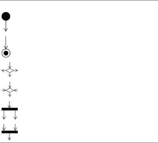
Table A-3. Other Frequently Used Activity Nodes
Notation |
Name of the Element and its Semantic |
|
|
|
Initial node Represents the point at which flow starts when the activity is invoked. |
|
An activity may contain more than one initial node; in this case invoking the activity |
|
will start multiple flows simultaneously. |
|
Activity final node This kind of node stops all flows in an activity. An activity may |
|
contain more than one activity final node; in this case the first one reached stops all |
|
flows and terminates the whole activity. |
|
Decision node This kind of node has one incoming edge and selects one outgoing |
|
edge from two or more possible outgoing flows. So-called guards (see the section |
|
called “Control Flow Edge”) are typically used to select the outgoing edge. |
|
Merge node This kind of node brings together multiple incoming alternate flows and |
|
has one single outgoing flow. |
|
Fork node This kind of node has one incoming edge and multiple outgoing edges |
|
and is used to split an incoming flow into multiple concurrent (parallel) flows. |
|
Join node This kind of node has multiple incoming edges and one outgoing edge |
|
and is used to synchronize incoming concurrent (parallel) flows. |
Sequence Diagram
Unlike the previously discussed activity diagrams, a sequence diagram depicts the interaction of, or communication between, elements of the modeled system in a specific, limited situation. They thus represent a different view of the behavior of the modeled system.
The sequence diagram in Figure A-17 depicts the sequence of interactions, that is, the ordered exchange of messages between all software modules involved in creating a new posting in an account.
469

Appendix A Small UML Guide
Figure A-17. The interaction of elements when creating a new account posting
Lifeline
The central element in sequence diagrams is the so-called lifeline.
LIFELINE
A lifeline represents an individual participant in an interaction.
The syntax (notation) of a lifeline, as depicted in Figure A-18, is a symbol that consists of a rectangle forming its “head” followed by a vertical dashed line that represents the lifetime of the participant. The head of the lifeline contains the information about the participant in the format elementName : elementType, whereby the elementName is optional.
Figure A-18. A lifeline representing the element a of type Type A
470