

- •Table of Contents
- •About the Author
- •About the Technical Reviewer
- •Acknowledgments
- •Software Entropy
- •Clean Code
- •C++11: The Beginning of a New Era
- •Who This Book Is For
- •Conventions Used in This Book
- •Sidebars
- •Notes, Tips, and Warnings
- •Code Samples
- •Coding Style
- •C++ Core Guidelines
- •Companion Website and Source Code Repository
- •UML Diagrams
- •The Need for Testing
- •Unit Tests
- •What About QA?
- •Rules for Good Unit Tests
- •Test Code Quality
- •Unit Test Naming
- •Unit Test Independence
- •One Assertion per Test
- •Independent Initialization of Unit Test Environments
- •Exclude Getters and Setters
- •Exclude Third-Party Code
- •Exclude External Systems
- •What Do We Do with the Database?
- •Don’t Mix Test Code with Production Code
- •Tests Must Run Fast
- •How Do You Find a Test’s Input Data?
- •Equivalence Partitioning
- •Boundary Value Analysis
- •Test Doubles (Fake Objects)
- •What Is a Principle?
- •KISS
- •YAGNI
- •It’s About Knowledge!
- •Building Abstractions Is Sometimes Hard
- •Information Hiding
- •Strong Cohesion
- •Loose Coupling
- •Be Careful with Optimizations
- •Principle of Least Astonishment (PLA)
- •The Boy Scout Rule
- •Collective Code Ownership
- •Good Names
- •Names Should Be Self-Explanatory
- •Use Names from the Domain
- •Choose Names at an Appropriate Level of Abstraction
- •Avoid Redundancy When Choosing a Name
- •Avoid Cryptic Abbreviations
- •Avoid Hungarian Notation and Prefixes
- •Avoid Using the Same Name for Different Purposes
- •Comments
- •Let the Code Tell the Story
- •Do Not Comment Obvious Things
- •Don’t Disable Code with Comments
- •Don’t Write Block Comments
- •Don’t Use Comments to Substitute Version Control
- •The Rare Cases Where Comments Are Useful
- •Documentation Generation from Source Code
- •Functions
- •One Thing, No More!
- •Let Them Be Small
- •“But the Call Time Overhead!”
- •Function Naming
- •Use Intention-Revealing Names
- •Parameters and Return Values
- •Avoid Flag Parameters
- •Avoid Output Parameters
- •Don’t Pass or Return 0 (NULL, nullptr)
- •Strategies for Avoiding Regular Pointers
- •Choose simple object construction on the stack instead of on the heap
- •In a function’s argument list, use (const) references instead of pointers
- •If it is inevitable to deal with a pointer to a resource, use a smart one
- •If an API returns a raw pointer...
- •The Power of const Correctness
- •About Old C-Style in C++ Projects
- •Choose C++ Strings and Streams over Old C-Style char*
- •Use C++ Casts Instead of Old C-Style Casts
- •Avoid Macros
- •Managing Resources
- •Resource Acquisition Is Initialization (RAII)
- •Smart Pointers
- •Unique Ownership with std::unique_ptr<T>
- •Shared Ownership with std::shared_ptr<T>
- •No Ownership, but Secure Access with std::weak_ptr<T>
- •Atomic Smart Pointers
- •Avoid Explicit New and Delete
- •Managing Proprietary Resources
- •We Like to Move It
- •What Are Move Semantics?
- •The Matter with Those lvalues and rvalues
- •rvalue References
- •Don’t Enforce Move Everywhere
- •The Rule of Zero
- •The Compiler Is Your Colleague
- •Automatic Type Deduction
- •Computations During Compile Time
- •Variable Templates
- •Don’t Allow Undefined Behavior
- •Type-Rich Programming
- •Know Your Libraries
- •Take Advantage of <algorithm>
- •Easier Parallelization of Algorithms Since C++17
- •Sorting and Output of a Container
- •More Convenience with Ranges
- •Non-Owning Ranges with Views
- •Comparing Two Sequences
- •Take Advantage of Boost
- •More Libraries That You Should Know About
- •Proper Exception and Error Handling
- •Prevention Is Better Than Aftercare
- •No Exception Safety
- •Basic Exception Safety
- •Strong Exception Safety
- •The No-Throw Guarantee
- •An Exception Is an Exception, Literally!
- •If You Can’t Recover, Get Out Quickly
- •Define User-Specific Exception Types
- •Throw by Value, Catch by const Reference
- •Pay Attention to the Correct Order of Catch Clauses
- •Interface Design
- •Attributes
- •noreturn (since C++11)
- •deprecated (since C++14)
- •nodiscard (since C++17)
- •maybe_unused (since C++17)
- •Concepts: Requirements for Template Arguments
- •The Basics of Modularization
- •Criteria for Finding Modules
- •Focus on the Domain of Your Software
- •Abstraction
- •Choose a Hierarchical Decomposition
- •Single Responsibility Principle (SRP)
- •Single Level of Abstraction (SLA)
- •The Whole Enchilada
- •Object-Orientation
- •Object-Oriented Thinking
- •Principles for Good Class Design
- •Keep Classes Small
- •Open-Closed Principle (OCP)
- •A Short Comparison of Type Erasure Techniques
- •Liskov Substitution Principle (LSP)
- •The Square-Rectangle Dilemma
- •Favor Composition over Inheritance
- •Interface Segregation Principle (ISP)
- •Acyclic Dependency Principle
- •Dependency Inversion Principle (DIP)
- •Don’t Talk to Strangers (The Law of Demeter)
- •Avoid Anemic Classes
- •Tell, Don’t Ask!
- •Avoid Static Class Members
- •Modules
- •The Drawbacks of #include
- •Three Options for Using Modules
- •Include Translation
- •Header Importation
- •Module Importation
- •Separating Interface and Implementation
- •The Impact of Modules
- •What Is Functional Programming?
- •What Is a Function?
- •Pure vs Impure Functions
- •Functional Programming in Modern C++
- •Functional Programming with C++ Templates
- •Function-Like Objects (Functors)
- •Generator
- •Unary Function
- •Predicate
- •Binary Functors
- •Binders and Function Wrappers
- •Lambda Expressions
- •Generic Lambda Expressions (C++14)
- •Lambda Templates (C++20)
- •Higher-Order Functions
- •Map, Filter, and Reduce
- •Filter
- •Reduce (Fold)
- •Fold Expressions in C++17
- •Pipelining with Range Adaptors (C++20)
- •Clean Code in Functional Programming
- •The Drawbacks of Plain Old Unit Testing (POUT)
- •Test-Driven Development as a Game Changer
- •The Workflow of TDD
- •TDD by Example: The Roman Numerals Code Kata
- •Preparations
- •The First Test
- •The Second Test
- •The Third Test and the Tidying Afterward
- •More Sophisticated Tests with a Custom Assertion
- •It’s Time to Clean Up Again
- •Approaching the Finish Line
- •Done!
- •The Advantages of TDD
- •When We Should Not Use TDD
- •TDD Is Not a Replacement for Code Reviews
- •Design Principles vs Design Patterns
- •Some Patterns and When to Use Them
- •Dependency Injection (DI)
- •The Singleton Anti-Pattern
- •Dependency Injection to the Rescue
- •Adapter
- •Strategy
- •Command
- •Command Processor
- •Composite
- •Observer
- •Factories
- •Simple Factory
- •Facade
- •The Money Class
- •Special Case Object (Null Object)
- •What Is an Idiom?
- •Some Useful C++ Idioms
- •The Power of Immutability
- •Substitution Failure Is Not an Error (SFINAE)
- •The Copy-and-Swap Idiom
- •Pointer to Implementation (PIMPL)
- •Structural Modeling
- •Component
- •Interface
- •Association
- •Generalization
- •Dependency
- •Template and Template Binding
- •Behavioral Modeling
- •Activity Diagram
- •Action
- •Control Flow Edge
- •Other Activity Nodes
- •Sequence Diagram
- •Lifeline
- •Message
- •State Diagram
- •State
- •Transitions
- •External Transitions
- •Internal Transitions
- •Trigger
- •Stereotypes
- •Bibliography
- •Index
Appendix A Small UML Guide
Structural Modeling
This section introduces the UML notations used to model structures, i.e. the building blocks of a software system, their interfaces, and their relationships (dependencies). Among the most important structural diagrams in UML are the component diagram and the class diagram.
Component
The UML element component represents a modular part of a system that is usually on a high abstraction level, for example at the level of software architecture. A component serves as a kind of “capsule” or “envelope” for a set of smaller components or classes that together fulfill certain functionality.
COMPONENT
A component represents a modular part of a system that encapsulates its contents and whose manifestation is replaceable within its environment.
The notation (syntax) of a component is a rectangular symbol with the component’s name, as depicted in Figure A-1. Above the component’s name (Billing), the keyword «component» appears within French quotation marks, which are also called guillemets. The icon in the upper-right corner is optional.
Figure A-1. An example of the notation of a billing component
Due to the fact that a component encapsulates its content, its services are defined in terms of so-called provided and required interfaces. Only these interfaces are available to the environment for the use of a component. That means that a component is a substitutable unit that can be replaced at design time or at runtime by another component that has compatible interfaces and offers equivalent functionality.
452
Appendix A SMALLmall UML GUIDEuide
Class andObject
Among various other applications, class diagrams are typically used to depict structures of an object-oriented software design. Class diagrams are at a lower level of abstraction than the previously discussed component diagrams. The central element in class diagrams is the class.
CLASS
A class describes a set of objects that share the same specifications of features, constraints, and semantics.
The notation (symbol) for a class is a simple rectangle with the name of the class, as depicted in Figure A-2.
Figure A-2. A class named Customer
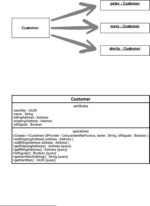
An instance of a class is commonly referred to as an object. Therefore, classes can be considered as blueprints for similar objects. If such objects are presented in a UML diagram, they are called instance specifications.2 The notation of an instance specification is very similar to that of a class, with the difference that its name is underlined. Figure A-3 depicts three instance specifications (“peter”, “mary”, and “sheila”) that were created by instantiating the same class.
2A linguistic subtlety: The background for this very special term “instance specification” is that the graphical representation of an instance (object) on a UML diagram is not the real object at all, it is just a specification of it in a model. The real object can be found in the memory of the running software system.
453
Appendix A Small UML Guide
Figure A-3. Three instance specifications created from the Customer class
Usually, classes have both structural and behavioral features. These are called attributes and operations.3 Attributes are usually shown in the second compartment of the class and operations in the third, as depicted in Figure A-4.
Figure A-4. The Customer class with attributes and operations
3In C++, the attributes of a class are sometimes called “members,” and the operations are sometimes called “methods” or “member functions,” whereby the last term is properly speaking not quite correct, because they are normally not true pure functions.
454

Appendix A Small UML Guide
The type of an attribute is noted separated by a colon after the attribute’s name. The same applies to the type of the return value of an operation. Operations can have parameters that are specified within parentheses. If an operation has more than one parameter, the parameters are noted as a comma-separated list. Static attributes or operations are underlined.
Classes have a mechanism to regulate the access to their attributes and operations. In UML they are called visibilities. The visibility kind is placed in front of the attribute’s or operation’s name and may be one of the characters described in Table A-1.
Table A-1. Visibilities
Character Visibility Kind
+public: This attribute or operation is visible to all elements that can access the class.
#protected: This attribute or operation is not only visible inside the class itself, but also visible to elements that are derived from the class that owns it (see the section entitled “Generalization”).
~package: This attribute or operation is visible to elements that are in the same package as its owning class. This kind of visibility cannot be realized in a language like C++ and is therefore not used in this book.
-private: This attribute or operation is only visible inside the class, nowhere else.
A C++ class definition corresponding to the UML class shown in Figure A-4 may look like Listing A-1.
Listing A-1. The Customer Class Implemented in C++
#include <string>
#include <string_view> #include "Address.h"
#include "UniqueIdentifierFactory.h"
class Customer { public:
Customer() = delete;
Customer(const UniqueIdentifierFactory& idProvider, std::string_view name, const bool isRegular);
virtual ~Customer() = default;
455
Appendix A Small UML Guide
void setShippingAddress(const Address& address); void setBillingAddress(const Address& address); Address getShippingAddress() const;
Address getBillingAddress() const; bool isRegular() const;
GUID getIdentifier() const;
std::string getIdentifierAsString() const;
private:
void requestUniqueIdentifier(const UniqueIdentifierFactory& identifierFactory);
GUID identifier; std::string name; Address billingAddress; Address shippingAddress; bool isRegular;
};
Note Due to the fact that a UML model is an abstraction in most cases (exception: when their purpose is to generate source code), diagrams often do not depict all existing properties of a described element, i.e., diagrams usually have a lower level of detail.
If a class is abstract, that is, it cannot be instantiated due to an incomplete specification, its name is typically shown in italicized letters, as depicted in Figure A-5. Abstract classes serve as base classes in inheritance hierarchies (see the section entitled “Generalization”).
Figure A-5. An abstract class called Shape
456