

- •Table of Contents
- •About the Author
- •About the Technical Reviewer
- •Acknowledgments
- •Software Entropy
- •Clean Code
- •C++11: The Beginning of a New Era
- •Who This Book Is For
- •Conventions Used in This Book
- •Sidebars
- •Notes, Tips, and Warnings
- •Code Samples
- •Coding Style
- •C++ Core Guidelines
- •Companion Website and Source Code Repository
- •UML Diagrams
- •The Need for Testing
- •Unit Tests
- •What About QA?
- •Rules for Good Unit Tests
- •Test Code Quality
- •Unit Test Naming
- •Unit Test Independence
- •One Assertion per Test
- •Independent Initialization of Unit Test Environments
- •Exclude Getters and Setters
- •Exclude Third-Party Code
- •Exclude External Systems
- •What Do We Do with the Database?
- •Don’t Mix Test Code with Production Code
- •Tests Must Run Fast
- •How Do You Find a Test’s Input Data?
- •Equivalence Partitioning
- •Boundary Value Analysis
- •Test Doubles (Fake Objects)
- •What Is a Principle?
- •KISS
- •YAGNI
- •It’s About Knowledge!
- •Building Abstractions Is Sometimes Hard
- •Information Hiding
- •Strong Cohesion
- •Loose Coupling
- •Be Careful with Optimizations
- •Principle of Least Astonishment (PLA)
- •The Boy Scout Rule
- •Collective Code Ownership
- •Good Names
- •Names Should Be Self-Explanatory
- •Use Names from the Domain
- •Choose Names at an Appropriate Level of Abstraction
- •Avoid Redundancy When Choosing a Name
- •Avoid Cryptic Abbreviations
- •Avoid Hungarian Notation and Prefixes
- •Avoid Using the Same Name for Different Purposes
- •Comments
- •Let the Code Tell the Story
- •Do Not Comment Obvious Things
- •Don’t Disable Code with Comments
- •Don’t Write Block Comments
- •Don’t Use Comments to Substitute Version Control
- •The Rare Cases Where Comments Are Useful
- •Documentation Generation from Source Code
- •Functions
- •One Thing, No More!
- •Let Them Be Small
- •“But the Call Time Overhead!”
- •Function Naming
- •Use Intention-Revealing Names
- •Parameters and Return Values
- •Avoid Flag Parameters
- •Avoid Output Parameters
- •Don’t Pass or Return 0 (NULL, nullptr)
- •Strategies for Avoiding Regular Pointers
- •Choose simple object construction on the stack instead of on the heap
- •In a function’s argument list, use (const) references instead of pointers
- •If it is inevitable to deal with a pointer to a resource, use a smart one
- •If an API returns a raw pointer...
- •The Power of const Correctness
- •About Old C-Style in C++ Projects
- •Choose C++ Strings and Streams over Old C-Style char*
- •Use C++ Casts Instead of Old C-Style Casts
- •Avoid Macros
- •Managing Resources
- •Resource Acquisition Is Initialization (RAII)
- •Smart Pointers
- •Unique Ownership with std::unique_ptr<T>
- •Shared Ownership with std::shared_ptr<T>
- •No Ownership, but Secure Access with std::weak_ptr<T>
- •Atomic Smart Pointers
- •Avoid Explicit New and Delete
- •Managing Proprietary Resources
- •We Like to Move It
- •What Are Move Semantics?
- •The Matter with Those lvalues and rvalues
- •rvalue References
- •Don’t Enforce Move Everywhere
- •The Rule of Zero
- •The Compiler Is Your Colleague
- •Automatic Type Deduction
- •Computations During Compile Time
- •Variable Templates
- •Don’t Allow Undefined Behavior
- •Type-Rich Programming
- •Know Your Libraries
- •Take Advantage of <algorithm>
- •Easier Parallelization of Algorithms Since C++17
- •Sorting and Output of a Container
- •More Convenience with Ranges
- •Non-Owning Ranges with Views
- •Comparing Two Sequences
- •Take Advantage of Boost
- •More Libraries That You Should Know About
- •Proper Exception and Error Handling
- •Prevention Is Better Than Aftercare
- •No Exception Safety
- •Basic Exception Safety
- •Strong Exception Safety
- •The No-Throw Guarantee
- •An Exception Is an Exception, Literally!
- •If You Can’t Recover, Get Out Quickly
- •Define User-Specific Exception Types
- •Throw by Value, Catch by const Reference
- •Pay Attention to the Correct Order of Catch Clauses
- •Interface Design
- •Attributes
- •noreturn (since C++11)
- •deprecated (since C++14)
- •nodiscard (since C++17)
- •maybe_unused (since C++17)
- •Concepts: Requirements for Template Arguments
- •The Basics of Modularization
- •Criteria for Finding Modules
- •Focus on the Domain of Your Software
- •Abstraction
- •Choose a Hierarchical Decomposition
- •Single Responsibility Principle (SRP)
- •Single Level of Abstraction (SLA)
- •The Whole Enchilada
- •Object-Orientation
- •Object-Oriented Thinking
- •Principles for Good Class Design
- •Keep Classes Small
- •Open-Closed Principle (OCP)
- •A Short Comparison of Type Erasure Techniques
- •Liskov Substitution Principle (LSP)
- •The Square-Rectangle Dilemma
- •Favor Composition over Inheritance
- •Interface Segregation Principle (ISP)
- •Acyclic Dependency Principle
- •Dependency Inversion Principle (DIP)
- •Don’t Talk to Strangers (The Law of Demeter)
- •Avoid Anemic Classes
- •Tell, Don’t Ask!
- •Avoid Static Class Members
- •Modules
- •The Drawbacks of #include
- •Three Options for Using Modules
- •Include Translation
- •Header Importation
- •Module Importation
- •Separating Interface and Implementation
- •The Impact of Modules
- •What Is Functional Programming?
- •What Is a Function?
- •Pure vs Impure Functions
- •Functional Programming in Modern C++
- •Functional Programming with C++ Templates
- •Function-Like Objects (Functors)
- •Generator
- •Unary Function
- •Predicate
- •Binary Functors
- •Binders and Function Wrappers
- •Lambda Expressions
- •Generic Lambda Expressions (C++14)
- •Lambda Templates (C++20)
- •Higher-Order Functions
- •Map, Filter, and Reduce
- •Filter
- •Reduce (Fold)
- •Fold Expressions in C++17
- •Pipelining with Range Adaptors (C++20)
- •Clean Code in Functional Programming
- •The Drawbacks of Plain Old Unit Testing (POUT)
- •Test-Driven Development as a Game Changer
- •The Workflow of TDD
- •TDD by Example: The Roman Numerals Code Kata
- •Preparations
- •The First Test
- •The Second Test
- •The Third Test and the Tidying Afterward
- •More Sophisticated Tests with a Custom Assertion
- •It’s Time to Clean Up Again
- •Approaching the Finish Line
- •Done!
- •The Advantages of TDD
- •When We Should Not Use TDD
- •TDD Is Not a Replacement for Code Reviews
- •Design Principles vs Design Patterns
- •Some Patterns and When to Use Them
- •Dependency Injection (DI)
- •The Singleton Anti-Pattern
- •Dependency Injection to the Rescue
- •Adapter
- •Strategy
- •Command
- •Command Processor
- •Composite
- •Observer
- •Factories
- •Simple Factory
- •Facade
- •The Money Class
- •Special Case Object (Null Object)
- •What Is an Idiom?
- •Some Useful C++ Idioms
- •The Power of Immutability
- •Substitution Failure Is Not an Error (SFINAE)
- •The Copy-and-Swap Idiom
- •Pointer to Implementation (PIMPL)
- •Structural Modeling
- •Component
- •Interface
- •Association
- •Generalization
- •Dependency
- •Template and Template Binding
- •Behavioral Modeling
- •Activity Diagram
- •Action
- •Control Flow Edge
- •Other Activity Nodes
- •Sequence Diagram
- •Lifeline
- •Message
- •State Diagram
- •State
- •Transitions
- •External Transitions
- •Internal Transitions
- •Trigger
- •Stereotypes
- •Bibliography
- •Index
Appendix A Small UML Guide
Behavioral Modeling
In addition to modeling static structures, UML also offers various possibilities to model the behavior of software, i.e. dynamic aspects and processes during the operation of the software. The three diagram types most commonly used for this purpose are activity diagrams, sequence diagrams, and state diagrams.
Since the total vocabulary range of UML is also relatively large, we will confine ourselves in this small introduction only to the elements that are necessary for understanding the behavioral diagrams presented in this book.
Activity Diagram
An activity diagram is suitable for describing complex processes (e.g., procedures, operations, etc.). The paths through the process described by an activity diagram can be divided and reunited, decisions can be made, and parallel regions may also exist, i.e. you can also describe concurrently running processes.
In general, an activity diagram consists of nodes and edges. The edges determine the processing order. The nodes are the elements that are brought into a certain order by the edges.
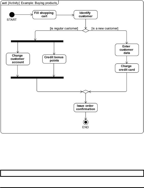
Figure A-14 depicts a simple example of an activity diagram. It shows that there are two alternative flows for regular customers and new customers, because regular customers already have a customer account, whereas new customers first have to
provide their data and then their credit card is charged. The diagram also shows that for regular customers, debiting the customer account and crediting the bonus points can run in parallel.
466
Appendix A Small UML Guide
Figure A-14. An activity diagram that depicts the process of purchasing products
Action
A very central element in activity diagrams is an executable node that is called action.
ACTION
An action is the fundamental unit of executable functionality.
467

Appendix A Small UML Guide
Actions are used to describe that something is happening in the modeled system, i.e. some kind of function or processing. The syntax (notation) of an action is a rectangle with rounded corners, as depicted in Figure A-15. The name of the action is usually the description of what is executed. Good and well-understandable action names consist of a noun and a verb.
Figure A-15. The notation of a simple action
There are many special kinds of actions in UML. For our purposes, the simple standard action (also called an opaque action), which describes by an expressive name what happens within the modeled system, is sufficient.
Control Flow Edge
In Figure A-16, the solid line with an open arrowhead connecting the action called “Fill shopping cart” to “Identify customer” is a control flow edge. This means that when the “Fill shopping cart” behavior is completed, control is passed to the action named “Identify customer”.
Figure A-16. A control flow edge connects two actions
A control flow edge can also have a so-called guard. Guards can be used, for example, to decide how a process in an activity will continue. A guard is depicted by a condition, which is a (Boolean) expression that can be evaluated to true or false, surrounded with square brackets, e.g., [is regular customer].
Other Activity Nodes
Table A-3 provides an overview with brief descriptions of the other nodes that can be seen in the activity diagram in Figure A-14.
468