

3728
.pdfIssue № 4 (40), 2018 |
ISSN 2542-0526 |
Asphalt concrete mixes with a recycled material are placed in the lower layer of a two-layered asphalt concrete surfacing.
A technological process of using an old asphalt concrete for preparing asphalt concrete mixes involves heating it to an operating temperature, cultivation and mixing. Larger pieces of an old asphalt concrete with a high percentage of bitumen is preliminarily crushed at the air temperature of more than 15…20 °С.
Following joining the bitumen emulsion with a mineral material, it starts decomposing with bitumen disintegrating from the water phase. Bitumen droplets are joined together forming a continuous film that joins the surface of the stone material. A period between the mixing and disintegration of the bitumen droplets from the water phase is called a time of disintegration.
Decomposition of the emulsion is accompanied by solidification where the amount of water in the mix decreases (first due to evaporation) as well as an increase in the tensile strength of the layer. It is necessary that prior to the layer being laid, the strength is chosen and there was cohesion between individual grains of the mix.
Decompositionandsubsequent solidificationoftheemulsiondeterminesthefollowingfactors:
––the rate of absorption of water with the stone material (rough, porous materials decrease the decomposition and seizure during water absorption from the emulsion);
––the humidity of the mix prior to the mixing the decomposition time depends on;
––the humidity of the mix following the compaction influencing the solidification rate;
––the granulometric composition of the mineral part and the resulting density;
––type and amount of the emulsion (a higher concentration of the emulsifier ions stabilizes the emulsion);
––a mechanical impact caused by the pump, compaction and transport loads;
––the composition of mineral materials as the solidification rate might depend on the physical and chemical interaction between the emulsion and surface of the material;
––the polarity of the surface of the stone material in relation to the electrical charge of the emulsion;
––the temperature of the mineral materials and the surrounding air as heat has an active influence on the chemical reactions and accelerates spreading and evaporation of water;
––the amount of mineral powder.
Cement is generally used in combination with a bitumen emulsion. Apart from improving the adhesion between the grains and moisture resistance of the surface, it acts as a catalyzer accelerating solidification, which causes quicker opening of traffic. The results of the study of
81
Russian Journal of Building Construction and Architecture
the properties of such a composite indicates that it is possible to add up to 5 % of the mass of cement with no significant decrease in fatigue characteristics of a reinforced layer.
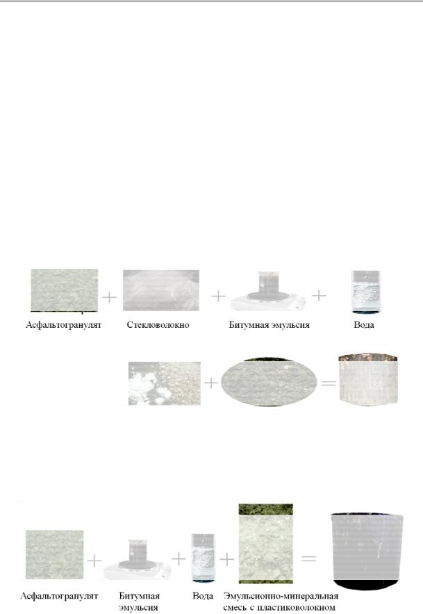
An increase in the strength of cation-active bitumen emulsions using additives of fibrous fillers allows the materials with higher crack resistance at high temperatures and resistance to plastic deformations in the summer season to be obtained.
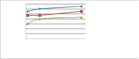
The dependence of the strength on the percentage of granulate and limestone at the percentage of 4 % of emulsion and 5 % of cement in a mix and different additives is shown in Fig. 7—8. The strength of the samples with a different composition is given in Fig. 9. [12, 13, 18].
The above changes in the properties of bitumen occur due to the following:
––fibers in combination with mineral particles generate a reinforcing base of an asphalt binder;
––absorption and higher specific surface of chrysotile mostly block bitumen;
––fibers increase adhesion of a binder and its viscocity more than regular mineral fillers.
|
|
Glass fiber |
|
|
|
|
Asphalt granulate |
Bitumen emulsion |
Water |
||||
|
|
|
|
|
|
|
Emulsion mineral mix
Fig. 7. Preparation of samples with glass fiber
Asphalt granulate |
|
Bitumen |
|
Water |
Emulsion mineral |
|
|
emulsion |
|
|
mix with plastic fiber |
|
|
|
|||
|
|
|
|
|
|
Fig. 8. Preparation of samples with plastic fiber
82
Issue № 4 (40), 2018 |
ISSN 2542-0526 |
Strength limit, MPa
 Sample with glass fiber
 Sample with plastic fiber
 Sample with no additives
Time, days
Fig. 9. Dependence of the strength of the samples with different compositions on the time
Conclusions
1.During studies an analytical method of determining the amount of new limestone depending on the percentage of residual bitumen in asphalt granulate was proposed.
2.Recurrent use of an asphalt granulate with a complex additive of cement and bitumen emulsion saves energetic and material resources and can be employed for laying the lower layer of a surfacing.
3.Thin-layered surfacings from emulsion mineral mixes laid based on the technology of cold recycling provide a standard coefficient of cohesion and protects a surface of a surfacing from a negative impact of natural and operational factors.
4.An increase in the strength of emulsion mineral mixes with additives of fiber fillers allow dispersion reinforced materials to be obtained that have a higher crack resistance at high temperatures and deformation stability.
References
1.Alferov V. I. Dorozhnye materialy na osnove bitumnykh emul'siy [Road materials based on bitumen emulsions]. Voronezh, Izd-vo Voronezh. gos. un-ta, 2003. 152 p.
2.Gorelov S. V. Ustroystva sloev iznosa dorozhnykh pokrytiy osnove kompleksno-modifitsirovannykh kationnykh bitumnykh emul'siy. Diss. kand. tekhn. nauk [Devices of wear layers of road surfaces based on com- plex-modified cationic bituminous emulsions. Cand. eng. sci. diss.]. Rostov-on-don, 2006. 199 p.
3.Dorozhkin V. R. Upravlenie kachestvom v stroitel'stve [Quality management in construction]. Voronezh. arkh.-stroit. un-t, 2010. 273 p.
4.Ivantsov V. A. [Physical and mechanical properties of mineral materials treated with emulsions]. Trudy SoyuzdorNII [Proc. of Soyuzdornii], 1969, vol. 34, pp. 91—102.
5.Lozikova Yu. G. Razrabotka tekhnologii ustroystva dorozhnykh pokrytiy na osnove effektivnykh bitumomineral'nykh kompozitsiy. Avtoref. diss. … kand. tekhn. nauk [Development of the technology of road surfaces on the basis of effective bitumen-mineral compositions]. Voronezh, 2015. 20 p.
83

Russian Journal of Building Construction and Architecture
6.Podol'skiy V. P., Turbin V. S., Alferov V. I. [Theoretical substantiation of road surface hardening by materials based on cationic bitumen emulsions]. Trudy mezhdunar. nauch.-prakt. konf. [Proc. of the international scien- tific-practical conference]. Minsk, BeldorNII Publ., 2001, pp. 100—106.
7.Podol'skiy V. P., Pospelov P. I., Glagol'ev A. V., Smirnov A. V. Tekhnologiya i organizatsiya stroitel'stva avtomobil'nykh dorog. Dorozhnye pokrytiya [Technology and organization of road construction. Pavement]. Moscow, Akademiya Publ., 2012. 304 p.
8.Podol'skiy Vl. P., Al' Addess M. Kh. Primenenie kationoaktivnykh bitumnykh emul'siy v Irake [Application of cationic bitumen emulsions in Iraq]. Nauka i tekhnika v dorozhnoy otrasli, 2016, no. 6, pp. 27—30.
9.Posobie po stroitel'stvu pokrytiy i osnovaniy avtomobil'nykh dorog i aerodromov iz gruntov, ukreplennykh vyazhushchimi materialami (k SniP 3.06.03-85 i SniP 3.06.06-88) [Manual for the construction of coatings and bases of roads and airfields of soils reinforced with binders (to SNiP 3.06.03-85 and SNiP 3.06.06-88)]. Moscow, SoyuzdorNII Publ., 1990. 256 p.
10.Rvacheva E. M. Ustroystvo poverkhnostnoy obrabotki s ispol'zovaniem emul'sionno-mineral'nykh smesey litoy konsistentsii NTOIS [Surface treatment device with the use of emulsion-mineral mixtures of cast NOIS consistency]. Moscow, Informavtodor Publ., 2000. No. 4. pp. 28—34.
11.Rezvantsev V. I. Primenenie bitumnykh emul'siy v Voronezhskoy oblasti [Application of bitumen emulsions in the Voronezh region]. Avtomobil'nye dorogi, 1969, no. 1, pp. 8—10.
12.Rudenskiy A. V., Kalgin Yu. I. Dorozhnye asfal'tobetonnye pokrytiya na modifitsirovannykh bitumakh
[Road asphalt concrete coatings on modified bitumen]. Voronezh, 2009. 143 p.
13.Taubman A. B., Koretskiy A. F. O roli strukturno-mekhanicheskogo bar'era v ustoychivosti emul'siy [On the role of structural-mechanical barrier in emulsion stability]. Kolloidnyy zhurnal, 1958, vol. 20, no. 5, pp. 676—681.
14.Shestakov V. P., Permyakov V. B., Vorozheykin V. M. Tekhnologicheskoe obespechenie kachestva stroitel'stva asfal'tobetonnykh pokrytiy [Technological quality assurance of asphalt concrete pavement construction]. Omsk, SIBADI Publ., 2009. 192 p.
15.Anderson J. Asphalt Emulsions in Paving Mixes: Open Graded and Dense Graded. Atlanta, Asphalt Emulsion Manufacturers Association, 1975.
16.Ban S., Hardin J. The Properties of Asphalt Emulsion Residue. Atlanta, Asphalt Emulsion Manufacturers Association, 1978.
17.Coyne L. D. Design and Construction of Emulsified-Asphalt Open-Graded Mixes and Overlays. USA, 1972.
163р.
18.Leech D. Cold-mix Bituminous Materials for Use in the Structural Layers of Roads. Project Report 75. Wokingham, Transport Research Laboratory, 1994. 25 р.
19.Mertens, E. W., Borgfeldt M. J. Cationic Asphalt Emulsionsю ABA CO Technical Publication no. 113. California Research Corporation, American Bitumuls and Asphalt Company, 1985.
20.Zoorob S. E., Thanaya I. N. A. Improving the performance of cold bituminous emulsion mixtures (CBEM’s) incorporating waste materials. Proc. of the 4th European Symposium on Performance of Bituminous and Hydraulic Materials in Pavement, BITMAT 4, University of Nottingham, UK, 11—12 April 2002. Amsterdam, 2002, pp. 237—249.
84

Issue № 4 (40), 2018 |
ISSN 2542-0526 |
UDC 625.717
V. P. Podol'skii1, A. N. Popov2, E. V. Makarov3,S. V. Nosov4
THEORETICAL BASIS FOR THE CALCULATION OF THE STRESS-STRAIN
OF A REPAIRED AIRFIELD COATING
Voronezh State Technical University
Russia, Voronezh, tel.: (473)236-18-89, e-mail: ecodor@bk.ru
1D. Sc. in Engineering, Prof., Head of the Dept. of Construction and Operation of Highways,
Military Educational and Scientific Center of the Air Force
«Air Force Academy Named after Professor N. Ye. Zhukovsky and Yu. A. Gagarin» Russia, Voronezh
2PhD in Engineering, Assoc. Prof., Head of the Dept. of Engineering and Airfield Support, tel.: +7-919-243-32-17 3PhD student of the Dept. of Engineering and Airfield Support,
tel.: +7-910-349-67-79, e-mail: e.vmakarov@yandex.ru Lipetsk State Technical University
Russia, Lipetsk, tel.: 8-903-699-3180, e-mail: nosovsegej@mail.ru
4D. Sc. in Engineering, Prof. of the Dept. of Building Materials Science and Road Technologies
Statement of the problem. The problem of the calculation of the stressed-strain of a reconstructed construction of the airfield cover for various boundary conditions was solved using the theoretical approaches suggested by the authors of this article. Their comparative analysis was carried out.
Results. The theoretical foundations of the analytical method for calculating stresses in a layered structure of a restored airfield coating under the influence of a static load and a numerical method for calculating the stress-strain of a repaired airfield coating using the software complex «Lira» are presented. The shortcomings of the analytical method of calculation are revealed, the specifics of the determination of the stress-strain in the program complex are shown allowing one to take into account the shortcomings. A comparative analysis of the results of stress analysis is carried out by means of two methods.
Conclusions. The study showed the possibility of calculating stresses using the methods proposed by the authors of the article. The analytical method is more suitable for preliminary calculations. The results of numerical modeling taking into account a greater number of input parameters allow us to assess the stress-strain more thoroughly, which is relevant for solving the research problems.
Keywords: repair layers, rigid airfield coatings, stress-strain.
Introduction. Adherence of a technical condition of an airfield surfacing to the requirements of guidelines is a prerequisite to an emergency-free operation of aircrafts. In the process of the operation of rigid airfield surfacing under the impact of operational loads defects that affect
© Podol'skii V. P., Popov A. N., Makarov E. V.,Nosov S. V., 2018
85

Russian Journal of Building Construction and Architecture
landing/takeoff safety and have no significant influence on the load-carrying capacity are inevitable. In order to maintain a necessary level of operational functionality and a normative service life of airfield surfacings, operational departments are engaged in organizing and performing planning and preventive works [12]. However, there are currently no regulations as to how they should be performed and what methods should be employed. As a result, in practice of operation of surfacing, a calculated service life of a reconstructed surfacing is not provided [7].
A calculated scheme of a repaired airfield surfacing is a two-layered structure. There are different approaches to calculating and constructing two-layered structures of rigid surfacings. Theoretical studies of stress and strain of multi-layered plates on an elastic foundation having a scientifically proven mathematical model that was originally set forth by E. I. Grigolyuk [3, 4], B. I. Коgan [5], V. S. Nikishin [14], А. V. Sinitsin [15]. The calculation of a multi-layered rigid airfield surfacing considering an operating reinforcement was proposed by V. A. Kulchitskiy [8—10]. In [1, 17, 18—22] a calculation of concrete surfacing reconstructed with a repairing layer along the entire area is discussed. However, obtained theoretical dependencies do not take into account the geometric parameters of a damaged area, which is due to how challenging it is to solve the task by means of an analytical method. Modern software allows the behavior of a reconstructed structure in different conditions to be modeled for a great number of input parameters and the size of a damaged area to be considered as well. In [16] there is a study of deformations of repaired areas of a rigid surfacing by means of a finite element method with no consideration of the effect of adhesive properties of a repairing material. Therefore no requirements for the physical and mechanical properties of repairing compositions, methods of calculating repaired areas of rigid airfield surfacing make it more daunting to choose a repairing material both at the stage of application and assessment of the durability of a restored structure.
The objective of the paper is to calculate a stress-strain of a restored structure of a airfield surfacing for different boundary conditions using the theoretical approaches suggested by the authors and performing their comparative analysis.
1. Аnalytical calculation of a layered structure of a restored airfield surfacing under the effect of a static load. An analytical calculation of the stress-strain of a repaired area of a rigid airfield surfacing under the impact of a wheel load of an aircraft is performed by solving the task of a bend of a non-restricted plate on an elastic foundation under the impact of a static load. A static scheme is chosen due to movement of an aircraft at small speeds (up to 30— 40 km/h) when the impact on a surfacing is comparable to a parking load from an aircraft support and at large speeds an unloading effect of a lifting force comes into action. As a cal-
86
Issue № 4 (40), 2018 |
ISSN 2542-0526 |
culation load В Fа a wheel load from the major support of an aircraft and its own weight is accepted. Due to quite large rigidity and insignificant bends of a concrete airfield surfacing under the impact of a mechanical load the Winkler model is used as a model of an elastic foundation where soil is viewed as a system of not connected springs supported by a rigid horizontal foundation characterized with a subbase coefficient K.
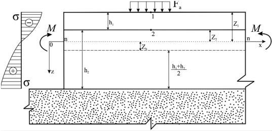
The calculation scheme (Fig. 1) is a two-layered structure lying on a continuous elastic foundation reconstructed along the entire area of a airfield surfacing. The upper layer of a repairing material with the thickness h1 is characterized with the elasticity modulus Е1 and compression strength limit R1, the lower layer is an existing surfacing with the thickness h2 with the elasticity modulus Е2 and the compression strength limit R2. A contact between a layer of a repairing composition and an existing surfacing is specified as ideal, which involves simultaneous operation of layers of a plate. The wheel load Fa is evenly distributed along a circle with the radius R and statistically applied to the center of a repaired area. In the plan the size of a repaired area of a rigid airfield surfacing is restricted with temperature stitches. A temperature impact on a structure is not considered. The axis x of a chosen system of the coordinates is in a neutral plane n−n, the axis z is perpendicularly directed down.
We are using large normal stresses at point 1 as a criterion of assessment of a change of stressstrain of a layered structure of a reconstructed airfield surfacing (the upper layer of a repairing material)asσ1, at point2 (atthe boundaryoflayersina material ofanexistingsurfacing) asσ2.
Fig. 1. Calculation scheme of a layered structure of a reconstructed airfield surfacing: Zh is the distance from an average to neutral plane of the plane;
Z1, Z2 is the distance from the axis x to the surface of a repairing and existing layer respectively; М is a bending moment; σ are normal stresses occurring in a body of a reconstructed structure of a airfield surfacing under the impact of a vertical load
87

Russian Journal of Building Construction and Architecture
According to [13], normal stresses are identified using the expressions:
|
M p |
, |
(1) |
|||
|
|
|||||
1 |
|
|
W1 |
|
||
|
|
|
|
|||
2 |
|
M p |
, |
(2) |
||
|
||||||
|
|
W2 |
|
|||
where Mp is a calculated bending moment, kg; W1 and W2 is a moment of resistance of a section of a repairing layer and existing surfacing respectively, сm2; ε = Е1/Е2 is a ratio of an elasticity modulus of a repairing and existing layers.
A moment of resistance of a section of a repairing layer and existing surfacing for the specified calculation scheme is determined using the formulas:
W |
2(ε I1 |
I2) |
, |
|
(3) |
||
|
|
|
|||||
1 |
h1 h2 |
2Zh |
|
|
|
||
|
|
|
|
||||
W W h1 h2 |
2Zh |
, |
(4) |
||||
2 |
1 h h |
2Z |
h |
|
|
||
|
2 |
1 |
|
|
|
|
|
where I1 and I2 are axial moments of inertia of a transverse section of the upper repairing layer and existing airfield surfacing respectively.
Axial moments of inertia of the transverse section of the above calculation scheme are found using the following dependencies:
I1 ZZ2 Z 2dA ZZ2 Z 2dZ 1Z 3I Z2 |
|
1( Z23 Z13) |
1 |
((h1 h2 |
Zh )3 (h2 h1 |
Zh )3), (5) |
||||||||||||||
1 |
|
I2 |
1 |
|
|
3 |
Z1 |
|
|
3 |
|
3 |
|
|
2 |
2 |
|
|||
|
|
Z1 |
2Z |
h Z 2dA Z1 |
2Z |
h Z 2dZ 1Z 3I ZZ1 2 2Zh |
1((Z1 2Zh )3 Z23) |
|||||||||||||
|
|
|
|
Z |
|
|
Z |
|
|
|
|
|
|
|
|
|
||||
|
1 |
|
|
|
|
2 |
|
|
2 |
|
|
3 |
1 |
|
|
3 |
|
|
(6) |
|
|
|
h1 h2 |
|
|
|
|
|
h2 h1 |
|
|
h1 h2 |
|
h2 h1 |
|||||||
|
(( |
Zh 2Zh )3 |
( |
Zh )3) |
(( |
Zh )3 ( |
Zh )3). |
|||||||||||||
3 |
|
|
3 |
|
|
|||||||||||||||
|
|
|
2 |
|
|
|
|
|
|
2 |
|
|
|
2 |
2 |
|
||||
The calculation bending moment occurring under the impact of load evenly distributed along the loading circle for the Winkler model is [11]
M p |
F l2 |
a(1 )f l (a), |
(7) |
|
a |
||||
4 |
||||
|
|
|
where Fa is an evenly distributed load along the circle, kg/сm2; f l(а) is a function as specified based on Table 1 [11]; µ is the Poisson coefficient, сm; l is an elastic characteristics of the layered structure, сm; a is a specified radius of the circle that the load is based on:
a |
R |
, |
(8) |
|
l |
||||
|
|
|
where R is a radius of a circle that equals the area of a print of a wheel pneumatics, сm.
88

Issue № 4 (40), 2018 |
ISSN 2542-0526 |
Таble 1
Standard values of the coefficient of operating conditions
|
The coefficient γ of operating conditions of rigid surfacing when airfield s are located |
||||||||||||
|
|
|
|
|
|
|
|
|
|
|
|
|
|
|
|
50о North |
|
between 43о and 50о |
|
43о South |
|
||||||
Airfield surfacing |
of northern altitude |
|
of northern altitude |
of northern altitude |
|||||||||
|
|
|
|
|
|
|
|
|
|
|
|
|
|
|
|
|
|
|
|
for groups of areas |
|
|
|
|
|
||
|
|
|
|
|
|
|
|
|
|
|
|
|
|
|
А |
|
B, C |
|
D |
А |
B, C |
|
D |
А |
B, C |
|
D |
|
|
|
|
|
|
|
|
|
|
|
|
|
|
Concrete |
0.8 |
|
0.9 |
|
1.1 |
0.75 |
0.85 |
|
1.05 |
0.7 |
0.8 |
|
1 |
|
|
|
|
|
|
|
|
|
|
|
|
|
|
Reinforced concrete |
0.9 |
|
1 |
|
1.2 |
0.85 |
0.95 |
|
1.15 |
0.80 |
0.90 |
|
1.1 |
|
|
|
|
|
|
|
|
|
|
|
|
|
|
According to SP (СП) “Airfield s” 121.13330.2012, the elastic characteristics of the layered structure of the repaired area of the airfield surfacing is determined using the formula:
l 4 |
D |
, |
(9) |
|
K |
|
|
where D is the rigidity of the layered structure, kg×сm; K is the subbase coefficient, kg/сm3. Having an impact on a airfield surfacing lying in the Winkler foundation and divided with temperature stitches into squares, the loads applied along one of the axis parallel to the sides of the plate, the structure bends along a cylindrical surface [11]. In this case the plate operates as a beam on an elastic foundation characterized with a cylindrical rigidity determined using the formula [11]:
D |
|
|
EI |
, |
(10) |
|
1 |
2 |
|||||
|
|
|
||||
where E is an elasticity modulus, kg/сm2; I is an inertia moment of a transverse section, сm3. In order to allow for the homogeneity of the materials of the layered reconstructed airfield plate, the cylindrical rigidity is replaced with a specified one considering a difference between the axial inertia moments of each layer [13]:
D |
|
E2(εI1 I2) |
. |
(11) |
|
||||
пр |
|
1 2 |
|
|
The structure is sufficiently strong if efforts from the calculated load are not more than those perceived by the section at the calculated resistance of the material given the coefficient of the operating conditions:
(12) where γ is the coefficient of the operating conditions of the reconstructed surfacing (see Table 1); R1,2 is the compressive strength limit of the repairing material and the plate concrete respectively, МPа.
89

Russian Journal of Building Construction and Architecture
A downside of the accepted calculation scheme is that it is impossible to allow for the adhesion of the repairing material to the plate concrete as well as to evaluate the influence of the sizes of the repaired area in the plan on the stress-strain of the structure.
2. Numerical modeling of the stress-strain of the deformed state of the repaired airfield surfacing under the impact of a static load. It is only possible to make the task at hand seemed as a real one involving repaired areas of a airfield surfacing, improve the subjectivity of the calculation results using a numerical modeling tool to evaluate not only the stress but also the deformations.
Numerical modeling of the reconstructed airfield surfacing under the impact of a static load by means of the finite element method in the form of the deflection method that employs the principle of possible deflections as a result of deformations [2]. The calculation is implemented in the Lira software based on the calculation scheme (Fig. 2).
Load evenly distributed along the wheel stamp of the aircraft
Runway plate |
|
Repairing material |
|
|
|
Adhesion of the repairing material with concrete
Elastic foundation
Fig. 2. Calculation scheme of a repaired area of a airfield surfacing:
h1 and h2 is the depth of the repaired area and the one of the surface which is being repaired respectively; а1 and а2 is the width of the repaired area and existing surfacing respectively
Compared to the calculation scheme for an analytical calculation (Fig. 1), the calculation scheme for numerical modeling has the following features: the repairedarea is restricted to the sizes in the plana1×b1,aconnectionbetweentherepairedmaterialandplateconcreteisspecified.
The geometric interpretation of the reconstructed structure of a airfield surfacing is implemented using two types of finite elements –– volumetric and two-node ones (Fig. 3).
90