

3728
.pdfIssue № 4 (40), 2018 |
ISSN 2542-0526 |
As seen in Fig. 4, the system is stable in a self-maintaining mode at the frequency of the closing of the shock valve of 4.58 Hz. The conditions when the dependences were obtained are as follows: a static pressure in the contour of impulse circulation of liquid is 315 KPа; a static pressure in the contour of pulsing circulation of liquid is 332 kPа; the consumption of the working medium through the shock valve 4.14 l/min; pumping consumption generated by the impulse pump is 0.28 l/min.
As seen from Fig. 4, as the shock valve closes in the pipeline area, there is a positive wave of a hydraulic shock of the working medium (the pressure goes up to 600 кPа) and behind the shock valve it is a negative wave (the pressure goes down to 100 kPa). A positive wave of distribution of a hydraulic shock provides displacement of an elastic diaphragm of the impulse pump for pushing out the pressure medium at a maximum pressure in an impulse of 400 kPа. This decrease in the pressure is due to damping of an impulse by compressed air in a hydraulic accumulator (see Fig. 2). At a negative wave of a hydraulic shock liquid from a hydraulic accumulator goes into the contour of pulsing input circulation of an impulse pump as its pressure goes down to 290 kPa.
Graphs in pressure pulsations presented in Fig. 4 allow one to establish the differences of the characteristics of impulse and pulsing flowing of liquid in pipelines. Impulse circulation is characterized with an instant increase in the pressure of the working medium before a closed shock node and conditions for its cavitation behind it. Pulsing circulation of the pressure liquid is smoother in terms of pressure pulsations and more identical tosinusoid given some assumptions. Considering practical assessment of the performance of the above scheme, it can be assumed that the use of this technical solution allows pulsing circulation of liquid to employ the kinetic energy of liquid of the second type moving impulsively. This can be used for intensifying heat exchange between these two contours by means of a water-to-water heat exchanger [6].
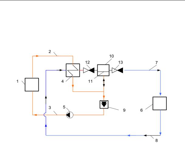
3. System of heat supply for independent users with impulse and pulsing circulation of a heat-carrier. A principal scheme of a heat supply system for independent users with impulse and pulsing circulation of a heat-carrier in its individual areas is presented in Fig. 5.
The system operates in the following way [17]. First it is filled with corresponding types of heat-carriers. Then using a network pump 5 circulation of a high-temperature heat-carrier is performed from the heat source 1 along the supply 2 and reverse 3 pipelines of a heat network through the heat-exchanger 3 of a heat network. As a specified speed of circulation of the high-temperature heat-carrier is achieved through the shock node 9, its passage section closes automatically and a hydraulic shock occurs. A positive wave of its distribution interacting
21
Russian Journal of Building Construction and Architecture
with the elastic diaphragm 11 of the impulse blower 10 causes pulsing circulation of a lowtemperature heat-carrier through the reverse input and output 13 valves 12 from one side in relation to the second side of the elastic diaphragm 11 along the distributing 7 and reverse 8 pipelines of the heat use system 6.
Fig. 5. System of heat supply for independent users with impulse circulation of a heat-carrier in the contour of a heat source and pulsing circulation in the contour of a heat use system:
1 is a heat source; 2, 3 is a supply and reverse pipelines of a heat network; 4 is a heat exchanger; 5 is a pump; 6 is a heat use system;
7, 8 is a supply and reverse pipelines of a heat use system;
9 is a shock node; 10 is an impulse blower; 11 is an elastic diaphragm; 12 is a reverse input valve; 13 is a reverse output valve
At the moment when a positive wave of distribution of a hydraulic shock spends all of its energy, the passage section of the shock node 9 opens automatically. Impulse circulation of the high-temperature heat-carrier in the supply 2 and reverse 3 pipelines of the heat network through the heat source 1 and heat-exchanger 4 by means of the network pump 5 restores and continues till the speed of the high-temperature heat-carrier reaches the value sufficient for automatic closing of the passage section of the shock node 9 again. Then the process repeats in the above sequence till the network pump 5 supplies the high-temperature heatcarrier from the heat soruce 1 to the supply 2 and reverse 3 pipelines of the heat network through the heat exchanger 4 and shock node 9.
22
Issue № 4 (40), 2018 |
ISSN 2542-0526 |
Conclusions
1.While investigating the operation of a self-maintaining water-lifting device based on twoliquid hydraulic ram, it can be concluded that its operation is accompanied by the generation of impulse and pulsing oscillation movement of liquid in its individual construction elements. This water-lifting device that was originally used only to supply water in open systems can be employed in an isolated water supply system as well for organizing a self-maintaining impulse and oscillation movement of liquid in individual contours.
2.Integration of the scheme solution of two-liquid hydraulic ram into a heat supply system for independent users allows one to [14]:
–– possibly organize impulse circulation of a heat-carrier in a hydraulic contour of a heat source and heat networks;
–– possibly transform the pressure from a heat network into that of a certain heat-use system, which allows financial costs for transporting a low-temperature heat-carrier to be reduced or, in some cases, avoided altogether;
–– possibly organize pulsing circulation of a heat-carrier in a heat use system.
3.Impulseand pulsing circulationofheat-carrierin different elements of a heatsupplysystemcan beusedforintensifyingheatexchange[7, 23] and performself-purification fromlimescale [18].
4.In order to optimize construction elements and parts of a heat supply system, it is possible to locally organize impulse and pulsing circulation of heat-carriers only within heating areas [10]. In order to reduce its metal consumption and mass, technical solutions for heat-exchange devices with an oscillation heat-exchange surface should be employed [11, 32].
References
1.Valueva E. P., Garyaev A. B., Klimenko A. V. Osobennosti gidrodinamiki i teploobmena pri techenii v mikrokanal'nykh tekhnicheskikh ustroystvakh [Features of hydrodynamics and heat transfer during flow in microchannel technical devices]. Moscow, 2016. 140 c.
2.Vilemas Yu. V., Voronin G. I., Dzyubenko B. V. e. a., Zhukauskasa A. A., Kalinina E. K., eds.
Intensifikatsiya teploobmena. Uspekhi teploperedachi — 2 [Intensification of heat transfer. The success of heat transfer—2]. Vilnius, Mokslas Publ., 1988. 188 p.
3.Galitseyskiy B. M., Ryzhov Yu. A., Yakush E. V. Teplovye i gidrodinamicheskie protsessy v koleblyushchikhsya potokakh [Thermal and hydrodynamic processes in oscillating flows]. Moscow, Mashinostroenie Publ., 1977. 256 p.
4.Ivanushkin S. G. Nestatsionarnyy sopryazhennyy teploobmen pri pul'siruyushchem techenii vyazkoy zhidkosti v kanalakh. Avtoref. diss. kand. tekhn. nauk [Non-stationary conjugate heat transfer at pulsating flow of viscous fluid in channels. Cand. eng. sci. diss.]. Tomsk, 1981. 13 p.
23

Russian Journal of Building Construction and Architecture
5.Isakeev A. I., Kiselev I. G., Filatov V. V.Effektivnye sposoby okhlazhdeniya silovykh poluprovodnikovykh priborov [Effective ways of cooling power semiconductor devices]. Leningrad, Energoizdat Publ., Leningr. otd-e, 1982. 136 p.
6.Levtsev A. P., Kudashev S. F., Makeev A. N., Lysyakov A. I. Vliyanie impul'snogo rezhima techeniya teplonositelya na koeffitsient teploperedachi v plastinchatom teploobmennike sistemy goryachego vodosnabzheniya [Influence of the pulse mode of the coolant flow on the heat transfer coefficient in the plate heat exchanger of the hot water supply system]. Sovremennye problemy nauki i obrazovaniya, 2014, no. 2. Available at: http://www.science-education.ru/116-12664
7.Levtsev A. P., Makeev A. N., Shirov M. S. Otsenka vliyaniya impul'snogo dvizheniya teplonositelya na teplovuyu moshchnost' zhidkostnogo okhladitelya [Assessment of the impact of the pulsed motion of the coolant on the thermal power of the liquid cooler]. Promyshlennaya energetika, 2017, no. 9, pp. 25—30.
8.Levtsev A. P., Makeev A. N. Impul'snye sistemy teplo- i vodosnabzheniya [Impulse systems of heat and water supply]. Saransk, Izd-vo Mordov. un-ta, 2015. 172 p.
9.Makeev A. N. [Use of hydraulic RAM in water and heat supply systems: 3 hours 3: technical Sciences]. XXXVII Ogarevskie chteniya [XXXVII Ogarev readings]. Saransk, 2009, pp. 8—11.
10.Makeev A. N. Teplovye punkty sistem teplosnabzheniya s impul'snoy tsirkulyatsiey teplonositelya [Heat points of heat supply systems with pulse circulation of the heat carrier]. Vestnik Dagestanskogo gosudarstvennogo tekhnicheskogo universiteta. Tekhnicheskie nauki, 2017, no. 1 (44), pp. 26—47. doi: 10.21822/2073- 6185-2017-44-1-37-47.
11.Makeev A. N. Teplopotreblyayushchie ustroystva dlya sistem teplosnabzheniya s impul'snoy tsirkulyatsiey teplonositelya [Heat-consuming devices for heat supply systems with pulsed coolant circulation].
Mekhanizatsiya stroitel'stva, 2017, no. 9, pp. 11—16.
12.Makeev A. N. Impul'snaya sistema teplosnabzheniya obshchestvennogo zdaniya. Diss. kand. tekhn. nauk [Impulse heating system of public building. Cand. eng. sci. diss.]. Saransk, 2010. 153 p.
13.Ovsepyan V. M. Gidravlicheskiy taran i tarannye ustanovki [The hydraulic RAM and RAM setup]. Moscow,
Mashinostroenie Publ., 1968. 124 p. |
|
|
14. |
Makeev A. N., Levtsev A. P. Sposob teplosnabzheniya [Heat supply method]. Patent |
RF, |
no. 2010112729/03, 2011. |
|
|
15. |
Levtsev A. P. e.a. Ustroystvo dlya pul'siruyushchey tsirkulyatsii rabochey sredy v zamknutom konture [De- |
|
vice for pulsating circulation of the working medium in a closed circuit]. Patent RF, no. 2016108210, 2017. |
|
|
16. |
Levtsev A. P., Makeev A. N., Ganina S. N. Taran gidravlicheskiy [Hydraulic RAM]. Patent |
RF, |
no. 2014115162/06, 2014. |
|
|
17.Levtsev A. P., Makeev A. N., Zyuzin A. M. Sistema teplosnabzheniya [Heat supply system]. Patent RF, no. 2010122249/03, 2010.
18.Pogrebnyak A. P., Kokorev V. L., Kokorev A. L., Moiseinko I. O., Gul'tyaev A. V., Efimova N. N. O vnedrenii sistem impul'snoy ochistki poverkhnostey nagreva [About introduction of systems of pulse cleaning of heating surfaces]. Novosti teplosnabzheniya, 2014, no. 1, pp. 22—24.
19.Rostovtsev V. N. Utilizatsiya malykh" padeniy vody dlya tseley osusheniya i orosheniya zemel' [Disposal of small drops of water for drainage and irrigation purposes]. Petrograd, 1916. 48 p.
24
Issue № 4 (40), 2018 |
ISSN 2542-0526 |
20.Fedotkin I. M., Lipsman V. S. Intensifikatsiya teploobmena v apparatakh pishchevykh proizvodstv [Intensification of heat transfer in the apparatus of food production]. Moscow, Pishchevaya promyshlennost' Publ., 1972. 240 p.
21.Ahn B., Ismailov M., Heister St. Experimental Study Swirl Injector Dynamic Response Using a
Hydromechanical Pulsator. Journal of Propulsion and Power, 2012, vol. 28, no. 3, pp. 585—595. doi: 10.2514/1.B34261.
22.Ali S., Habchi Ch., Menanteau S., Lemenand Th., Harion J.-L. Heat Transfer and Mixing Enhancement by Free Elastic Flaps Oscillation. International Journal of Heat and Mass Transfer, 2015, vol. 85, pp. 250—264. doi: 10.1016/j.ijheatmasstransfer.2015.01.122.
23.Bayomy A. M., Saghir M. Z. Heat Transfer Characteristics of Aluminum Metal Foam Subjected to a Pulsating/Steady Water Flow: Experimental and Numerical Approach. International Journal of Heat and Mass Transfer, 2016, vol. 97, pp. 318—336. doi: 10.1016/j.ijheatmasstransfer.2016.02.009.
24.Chaohong G., Xuegong H., Wei C., Dong Y., Dawei T. Effect of Mechanical Vibration on Flow and Heat Transfer Characteristics in Rectangular Microgrooves. Applied Thermal Engineering, 2013, vol. 52, iss. 2, pp. 385—393. doi: 10.1016/j.applthermaleng.2012.12.010.
25.Harith M. N., Bakar R. A., Ramasamy D., Quanjin M. A Significant Effect on Flow Analysis & Simulation Study of Improve Design Hydraulic Pump. 4th International Conference on Mechanical Engineering Research (ICMER—2017). IOP Conference Series: Materials Science and Engineering, 2017, vol. 257 (1), pp. 1—14. doi: 10.1088/1757-899X/257/1/012076.
26.Hussin N. S. M., Gamil S. A., N. Amin A. M. e.a. Design and Analysis of Hydraulic Ram Water Pumping
System / N. S. M. Hussin [et al.]. Journal of Physics: Conference Series, 2017, no. 908 (1), pp. 1—8. doi: 10.1088/1742-6596/908/1/012052.
27.Jiadong J., Peiqi G., Wenbo B. Numerical Analysis on Shell-side flow-induced Vibration and Heat Transfer Characteristics of Elastic Tube Bundle in Heat Exchanger. Applied Thermal Engineering, 2016, vol. 107, pp. 544—551. doi: 10.1016/j.applthermaleng.2016.07.018.
28.Léal L., Miscevic M., Lavieille P. e.a. An Overview of Heat Transfer Enhancement Methods and New Perspectives: Focus on Active Methods Using Electroactive Materials. International Journal of Heat and Mass Transfer, 2013, vol. 61, pp. 505—524. doi: 10.1016/j.ijheatmasstransfer.2013.01.083.
29.Levtzev А. P., Makeev A. N., Kudashev S. F. Pulsating Heat Transfer Enhancement in the Liquid Cooling System of Power Semiconductor Converter. Indian Journal of Science and Technology, 2016, vol. 9 (11), pp. 1—5. doi: 10.17485/ijst/2016/v9i11/89420.
30.Sayar E. Heat Transfer from an Oscillated Vertical Annular Fluid Column Through a Porous Domain: a Thermodynamic Analysis of the Experimental Results. Isi Bilimi Ve Teknigi Dergisi-Journal of Thermal Science and Technology, 2017, vol. 37, no. 2, pp. 1—12. wos: 000417668600001.
31.Slavnic D. S., Bugarski B. M., Nikazevic N. M. Oscillatory Flow Chemical Reactors. Hemijska industrija, 2014, vol. 68, no. 3, pp. 363—379. doi: 10.2298/HEMIND130419062S.
32.Su Y., M. Li, M. Liu, G. Ma A Study of the Enhanced Heat Transfer of Flow-Induced Vibration of a New Type of Heat Transfer Tube Bundle — the Planar Bending Elastic Tube Bundle. Nuclear Engineering and Design, 2016, vol. 309, pp. 294—302. doi: 10.1016/j.nucengdes.2016.09.012.
25

Russian Journal of Building Construction and Architecture
UDC (519.9 + 518.5) : 532.54
G. N. Martynenko1, D. N. Kitaev2, А. А. Sedaev3
PROSPECTS FOR THE DEVELOPMENT OF THE GAS SUPPLY SYSTEM OF THE CITY DISTRICT OF VORONEZH FOR THE PERIOD TILL 2035
Voronezh State Technical University
Russia, Voronezh
1PhD in Engineering, Assoc. Prof. of the Dept. of Heat and Oil and Gas Business, tel.: +7-900-304-62-51, e-mail: glen2009@mail.ru
2PhD in Engineering, Assoc. Prof. of the Dept. of Heat and Oil and Gas Business
3D. Sc. in Mathematics and Physics, Assoc. Prof. of the Dept. of Applied Mathematics and Mechanics, tel.: (473) 271-53-62, e-mail: sed@vmail.ru
Statement of the problem. The prospects for long-term development of the gas industry in Voronezh in accordance with «Strategy of Socio-Economic Development of the Voronezh Region for the period till 2035» of the Department of Economic Development of the Voronezh region are considered.
Results. The current state of the gas supply system in Voronezh from 2011 to 2017 is investigated. A system of program activities necessary for the implementation of the Strategy is developed. Conclusions. As a result of the analysis of statistical data on the gas economy of Voronezh from 2011 to 2017, events justified due to new buildings, the requirements for higher reliability of gas pipelines, trouble-free and continuous operation of gas stations are proposed. All the events are approved and taken into consideration by Ltd. “Gazprom Gas Distribution Voronezh“.
Keywords: gas supply, development prospects, gas supply system, Voronezh.
Introduction. According to “The Strategy for Social and Economic Development of Voronezh region till 2035”, the Department for Economic Development of Voronezh region sets ambitious goals for high rates of residential construction in Voronezh and Voronezh region as well as makes long-term plans for highand low-rise construction. Therefore Voronezh region can be described as a region that is currently leading the way in residential construction and this trend is set to continue. According to the analysis of a current state of the infrastructure of Voronezh region, the main task facing the industry is designing, operation and reconstruction of objects of a communal system including water, heat, gas and energy supply [2, 8, 9, 12].
© Martynenko G. N., Kitaev D. N., Sedaev А. А., 2018
26
Issue № 4 (40), 2018 |
ISSN 2542-0526 |
Shortand long-term analyses of gas supply systems are necessary. These systems need to be looked at in more detail as they are rather challenging to operate and keep safe [1, 3—6].
1. Current state of the gas supply system of Voronezh. Gas is supplied from the main pipeline Middle Asia –– Center using five gas distribution stations (GDS) that are part of the branch “Voronezh Department of Main Pipelines” of Ltd. “Gazprom Transgaz Moscow”. The established capacity of the GDS supplies gas to current buildings (Table 1). GDS 1, 3, 4 are located on the right bank, GDS 2, 5 are on the left bank of the River Voronezh.
|
|
Current loads on the GDS of the city of Voronezh |
Таble 1 |
|||
|
|
|
||||
|
|
|
|
|
|
|
|
|
|
|
Productivity, |
|
|
№ |
Name |
Start of the |
Length, km |
thousand m3/h |
Used |
|
operation |
|
|
capacity, % |
|||
|
|
|
project |
Actual current |
||
|
|
|
|
gas consumption |
|
|
|
|
|
|
|
|
|
|
GDS № 1 |
|
|
|
|
|
1 |
Р = 12 atm |
1957—1972 |
6.12 |
250 |
185.4 |
74.16 |
|
Р = 12 atm |
|
|
|
|
|
|
|
|
|
|
|
|
|
GDS № 2 |
1964 |
19.80 |
250 |
132.5 |
53.00 |
2 |
Р = 6 atm (SBK1-30) |
|
|
|
|
|
|
BK GDS 2-30 |
|
|
|
|
|
|
Р = 12 atm |
1985 |
19.80 |
30 |
17.7 |
59.00 |
|
|
|
|
|
|
|
3 |
GDS Teplichniy |
1972 |
0.28 |
80 |
25.7 |
32.13 |
Р = 12 atm |
||||||
|
|
|
|
|
|
|
4 |
GDS Yamnoe |
1987 |
23.2 |
120 |
55.3 |
46.08 |
|
Р = 12 atm |
|
|
|
|
|
|
|
|
|
|
|
|
|
GDS № 3, Somovo |
|
|
|
|
|
5 |
Р = 6 atm |
1996 |
72.4 |
200 |
67.5 |
33.75 |
|
Р = 12 atm |
|
|
|
|
|
|
|
|
|
|
|
|
Heat stations, boiler-rooms, industrial enterprises, communal household institutions and in households these are gas stoves, circulating and capacitive water heaters, heating facilities are supplied with natural gas in Voronezh. The technical data on the gas facilities as of January 1, 2017 is presented in Table 2.
There are currently 197 gas-regulating stations and cabinet-type gas-regulating stations in use which are over 20 years old. As for telemetry, the numbers are the following: in Kominternovskiy district there are 9 out of 130 regulating stations, in Leninskiy district ––
27

Russian Journal of Building Construction and Architecture
12 out of 65, in Levoberezhniy district 9 out of 82, in Zheleznodorozhniy 5 out of 53, in Sovetskiy district 15 out of 91.
|
Technical Data on Gas Household as of January 1, 2017 |
Таble 2 |
|
|
|
||
|
|
|
|
№ |
Gas User |
Number |
|
|
|
|
|
1 |
Gasification of the housing stock |
|
|
|
|
|
|
1.1 |
Apartments (housing stock) |
364099 |
|
|
|
|
|
|
Number of apartments supplied with gas: |
338908 |
|
1.2 |
|
|
|
–– including natural gas |
347884 |
||
|
|
|
|
|
–– liquefied gas |
1024 |
|
|
|
|
|
1.3 |
Level of natural gas supply, % |
96.8 |
|
|
|
|
|
2 |
Characteristics of a natural gas supply system |
|
|
|
|
|
|
2.1 |
Length of external gas pipelines served by Ltd. “Gazprom Gas Distribution Voro- |
2775.99 |
|
nezh” in Voronezh, km |
|
||
|
|
|
|
|
According to the material: |
|
|
2.1.1 |
|
|
|
–– steel, km |
2361.545 |
||
|
|
|
|
|
–– polyethylene, km |
414.445 |
|
|
|
|
|
|
According to the pressure: |
|
|
|
|
|
|
|
–– high Class I (0.6—1.2 МPа), km |
19.103 |
|
2.2.2 |
|
|
|
–– high Class II (0.3—0.6 МPа), km |
211.235 |
||
|
|
|
|
|
–– medium, km |
237.587 |
|
|
|
|
|
|
–– low, km |
2308.065 |
|
|
|
|
|
|
According to the laying method: |
|
|
|
|
|
|
2.2.3 |
–– overground, km |
658.161 |
|
|
–– underground, km |
2111.789 |
|
|
|
|
|
|
–– underwater, km |
6.040 |
|
|
|
|
|
3 |
Number of gas-regulating stations in use (GRS): |
186 |
|
|
|
||
–– including those of over 20 years old |
127 |
||
|
|||
|
|
|
|
|
Number of cabinet-type gas-regulating stations (CRS): |
376 |
|
|
|
|
|
4 |
–– including those with the regulator capacity of over 50 m3/h |
89 |
|
–– with the regulator capacity of up to 50 m3/h |
287 |
||
|
|||
|
–– of over 20 years old |
70 |
|
|
|
|
|
5 |
Number of gas-regulating facilities in use |
21 |
|
|
|
|
|
6 |
Communal household institutions supplied with gas |
416 |
|
|
|
|
|
7 |
Industrial enterprises supplied with gas |
135 |
|
|
|
|
|
8 |
Boilers supplied with gas: |
558 |
|
|
|
||
–– including those with roofs |
52 |
||
|
|||
|
|
|
28
Issue № 4 (40), 2018 |
ISSN 2542-0526 |
|
|
|
End of Table 2 |
|
|
|
№ |
Gas User |
Number |
|
|
|
9 |
Number of household gas stoves |
329419 |
|
|
|
10 |
Number of circulating water heaters |
125727 |
|
|
|
11 |
Number of capacitive water heaters |
42551 |
|
|
|
12 |
Number of household heating facilities |
10584 |
|
|
|
13 |
Number of gas-fuel heating furnaces |
6392 |
|
|
|
|
Numberofelectricalchemicalprotectionfacilitiesonundergroundsteelgaspipelines: |
432 |
|
|
|
14 |
–– including cathode ones |
304 |
|
|
|
–– drainage |
79 |
|
|
|
|
|
–– tyre-tread |
49 |
|
|
|
15 |
Protection of gas pipelines |
100 |
|
|
|
As for underground gas pipelines, of up to 15 years old — 631.123 km, from 16 to 30 years old — 358.891 km, from 31 to 35 years old — 50.481 km, from 36 to 38 years old — 155.580 km, of 39 years old — 55.822 km, of 40 years old — 43.788 km, from 41 to 50 years old — 402.002 km, from 51 to 60 years old — 5.697 km. The gas pipelines of over 40 years old were tested. Two underground medium-pressure passages cross the Voronezh water reservoir for cross-feeding of a gas supply system of the right and left banks, d325 and d377 mm. The results of a recent study in 2012 showed that at some spots the gas pipelines is torn — the depth of 0.2 m up to the top of the pipe instead of the one at 1.0 m, the insulation is satisfactory.
65 out of 432 facilities for electrical and chemical protection are in need of replacement. As there are not enough facilities for telemechanization and automatization of technological processes associated with gas supply, it is challenging to get a clear idea of the consumption of a target product. Therefore saving such an energy resource as natural gas is daunting as well.
There are enough enterprises in the city that are in need of natural gas for technology, heating, ventilation and hot water supply. There are users residing outside the city where gas is supplied from the city’s gas distribution gas pipelines (Table 3).
Despite the fact that from December 15, 2008 Somovo and areas such as Borovoe, Maslovka, Nikolskoe, Tavrovo, Semilukskie Vyselki are in the authority of “Gazprom Mezhregiongaz Novaya Usman Private Structural Department”, gas is also supplied from the city’s gas supply system.
29

Russian Journal of Building Construction and Architecture
Таble 3
Data on the annual and maximum hourly fuel consumption according to the users residing outside the city where gas is supplied with the city’s gas distribution pipelines over a reported period
Name and address of the user |
GRS |
Fuel consumption |
||
|
|
|||
thousand m3/year |
m3/hour |
|||
|
|
|||
State Farm “Zarechenskiy” |
GRS № 2 |
7500.0 |
3000 |
|
|
|
|
|
|
Podgornoe |
GRS Yamnoe |
6250.0 |
2500 |
|
|
|
|
|
|
Pervoe Maya |
GRS № 1 |
6250.0 |
2500 |
|
|
|
|
|
|
State Farm Nikolskiy |
GRS № 2 |
2290.0 |
916 |
|
|
|
|
|
|
Malyshevo |
GRS № 1 |
2750.0 |
1100 |
|
|
|
|
|
|
Gas distribution station in Podgornoe |
GRS Yamnoe |
52000.0 |
20800 |
|
|
|
|
|
|
Cattle factory “Maslovskiy” |
GRS № 2 |
7720.0 |
3000 |
|
|
|
|
|
|
Podkletnoe |
GRS № 2 |
7500.0 |
3000 |
|
|
|
|
|
|
Yamnoe |
GRS Yamnoe |
7500.0 |
3000 |
|
|
|
|
|
|
Maslovka |
GRS № 2 |
4600.0 |
1840 |
|
|
|
|
|
|
Shuberka |
GRS № 3 |
3530 |
1715 |
|
|
|
|
|
|
Novaya Usman |
GRS № 2 |
41391 |
18000 |
|
|
|
|
|
|
Repnoe |
GRS № 3 |
21000 |
10000 |
|
|
|
|
|
|
Otradnoe |
GRS № 3 |
6450 |
3100 |
|
|
|
|
|
|
2. Long-term measures for improving the reliability of a gas distribution system. For a reliable gas supply [7, 13, 14, 16] it is necessary to design or restructure for bigger diameters high-, medium-, low-pressure gas pipelines in new areas as well as to build a gas regulating station (GRS).
It is necessary and obligatory to maintain the gas pipelines which are over 39 years old. As the gas supply system of Voronezh is further developed, it will be essential to allow for a likely construction of gas distribution stations as there is a mass construction of objects outside the city where gas is supplied and no sufficient capacities to keep up with the demand.
It is also important to reconstruct the existing steel gas pipelines, which are in poor condition, by means of polymer technologies. Pipe-canal underground passages should be restored with a polymer hose going through a pipeline and stuck with a two-component sealing glue using the technology by Saratov Head Scientific Research and Project Institute in Gas Distribution and Use GIPRONIIGAZ. Up to 2020 it is also essential to restore underground passages to the existing thermal electric stations and large boiler-rooms using polymer materials based on the “pipe-to-pipe” technology [17].
For more optimal gas supply in the future [18, 21—23] it is necessary to provide a stable gas pressure at the user’s end by sequentially supplying gas from a low-pressure to a medium-
30