

3728
.pdfIssue № 4 (40), 2018 |
ISSN 2542-0526 |
was decomposed in a Fourier row (2) followed by the use of the superposition method. A formula for maximum modal dynamism coefficient corresponding with the k-th form of oscillations with own frequency fk was obtained:
NF |
|
|
|
|
|
rn |
|
|
|
|
|
fk 1 |
|
|
|
|
|
|
|
, |
(3) |
||
|
|
n |
2 |
2 |
2 |
|
2 k nfp |
2 |
|||
n 1 |
|
|
|
||||||||
|
1 |
|
|
fp |
|
|
|
|
|
||
|
|
|
2 |
|
|
|
|||||
|
|
|
|
|
|
|
|
|
|
|
|
|
|
|
|
fk |
|
|
fk |
|
|
||
where NF is a number of confined members of the row (2); ξk is a modal damping coefficient; fp is an excitement frequency, Hz. In Fig. 1 there is a graph of a dynamism coefficient in the axis of own frequencies β(fk) at the frequency of impulses fp = 2 Hz for high jumps (α = 1/4) and damping 6.53 % (ξ1 = 0.0653 is a damping coefficient for the lowest own frequency corresponds with the below model of a stand).
|
18 |
|
|
|
|
|
|
|
|
|
|
|
16 |
|
|
|
|
|
|
|
|
|
|
|
14 |
|
|
|
|
|
|
|
|
|
|
|
12 |
|
|
|
|
|
|
|
|
|
|
β |
10 |
|
|
|
|
|
|
|
|
|
Fig. 1. Dynamism coefficient |
|
8 |
|
|
|
|
|
|
|
|
|
|
|
6 |
|
|
|
|
|
|
|
|
|
|
|
4 |
|
|
|
|
|
|
|
|
|
|
|
2 |
|
|
|
|
|
|
|
|
|
|
|
00 |
2 |
4 |
6 |
8 |
10 |
12 |
14 |
16 |
18 |
20 |
|
|
|
|
|
|
f, Hz |
|
|
|
|
|
It should be emphasized that in the formula (3): first, a simultaneous maximum response to all the harmonic components of an external load not considering their phases is employed; secondly, possible inconsistency of the process is not considered; thirdly, the damping coefficient is accepted to be constant and equals ξ1.
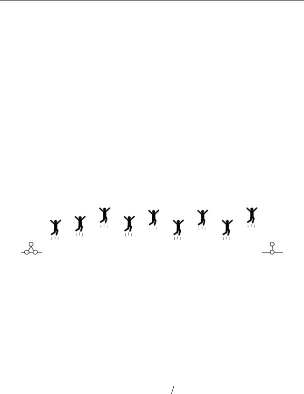
2. Stating the problem and designing static modeling. As the simplest model of a stand, let us accept a hinged beam (Fig. 2). A beam with the length of 6 m has a double-tee profile chosen based on the density for a maximum static load. A load from 9 spectators is specified as
101
Russian Journal of Building Construction and Architecture
concentrated forces with the step of 0.6 m. Each force changes in time according to the semisinusoid impulse law with a random amplitude and phase (i = 1, …, 9):
|
|
|
t |
|
|
|
|
|
|
|
|
G sin |
|
|
, |
0 t T |
, |
|
|
|
|
|
|||||||
Fi t 2 |
i |
|
Tp |
i |
|
p |
|
(4) |
|
|
|
|
|
|
|
||||
|
Tp t Tp . |
|
|
|
|
||||
0, |
|
|
|
|
|||||
During a series of numerical experiments it was assumed that the amplitude Gi (a spectator’s weight) and a phase φi are evenly distributed random values. равномерно Let a spectator’s mass be able to vary from 70 to 100 kg, then 700 ≤ Gi ≤ 1000 Н. Besides, for each spectator there was allowed to be a delay. With a delay from 0 to 1 sec the phase φi changed randomly from 0 to (π 1) / αTp. The random values i and φi, which are different for each spectator, are generated using a sensor of random numbers before the start of each numerical experiment. A more dangerous variant of spectators’ activity was considered, i.e. high jumps (α = 1/4) with the frequency of 2 Hz.
|
|
|
|
|
|
|
|
|
1 |
2 |
3 |
4 |
5 |
6 |
7 |
8 |
9 |
Fig. 2. Model of a stand with spectators
The objective of the numerical experiment was to identify displacement of a central section of the beam under a static load (the spectators are standing) and a dynamic one (the spectators are jumping high) as well as to evaluate coefficients of dynamism and inconsistency. A coefficient of inconsistency will be defined as a ratio of dynamism coefficients for an inconsistent (obtained as a result of a numerical experiment considering random amplitudes and phase) βэксп and completely consistent processes:
K эксп |
. |
(5) |
In order to solve the task, the method of direct integration of a movement equation was employed in a time range in a simulation environment Simulink in the MatLab software.
The plan of the numerical experiment is as follows:
1. Designing a finite-element model, specifying node transformations u, forming a matrix of rigidity K and inertia M using the finite element method. Specifying a matrix of damping
102
Issue № 4 (40), 2018 |
ISSN 2542-0526 |
B based on a model of internal friction. Determining own frequencies of the damping models and parameters;
2.Specifying the amplitude and phase for each concentrated force (a sensor of random numbers is used); designing a vector of node static loads from the spectators’ weight G and a vector of random phases φ;
3.Designing a calculation static model of the beam. The solution of the equation of static balance considering own weight of the beam is the following:
Ku G. Determining a static bend ucm in the centre of the beam;
4. Designing a calculation dynamic model of the beam. The movement equation:
Mu Bu Ku F t ,
where F(t) is a vector of a dynamic load with the elements (4) is solved by direct numerical integration in Simulink. Identifying a maximum dynamic displacement for transitional and established modes;
5. Identifying a dynamism coefficient as a ratio of a dynamic displacement to a static one. Determining an inconsistency coefficient (5).
Numerical modeling included a series of 10 experiments (steps 1—4). As a result, implementation of random coefficients of dynamism and inconsistency was obtained and their mathematical expectation and standard was identified.
3. Modeling results. The following cases were considered as part of the numerical experiment. 1. Non-resonance mode: beam (double-tee № 16) with the length of 6 m is divided into 10 bar finite elements with the length of 0.6 m each; for determining the matrices of rigidity, inertia and damping the method of finite elements was employed. A finite-element mdoel of the stand includes 20 node degrees of freedom: 9 linear displacements and 11 node ones (considering the boundary conditions); the lowest own frequency of the beam is 14.6 Hz (91.7 rad/sec), which is considerably higher than the impact frequency of 2 Hz, damping is 6.53 %. The dynamism coefficient not considering inconsistency according to the formula (3) is β(14.6 Hz) = 9.02 (see Fig. 1). The results of statistical modeling for the series of 10 numerical experiments can be found in Table 1.
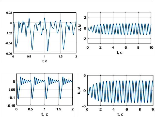
Here are the displacements of a central section for static loading, dynamic displacements for the established and non-established forced vibrations, experimental coefficients of dynamism and inconsistency. Fig. 3а shows one of the obtained functions of displacements in time.
103

Russian Journal of Building Construction and Architecture
Таble 1
Results of the series of 10 experiments. Non-resonance mode.
Displacements of a central section (according to a module), coefficients of dynamism and inconsistency
Number |
|
|
Udyn, m |
|
Βexp |
|
K |
|||
Ust, m |
|
|
(formula (5), β = 7.15) |
|||||||
of the experiment |
|
|
|
|
|
|
||||
|
|
Н |
|
У |
Н |
|
У |
Н |
|
У |
|
|
|
|
|
|
|
|
|
|
|
1 |
0.015 |
0.039 |
|
0.038 |
2.639 |
|
2.558 |
0.38 |
|
0.37 |
|
|
|
|
|
|
|
|
|
|
|
2 |
0.015 |
0.047 |
|
0.037 |
3.170 |
|
2.524 |
0.45 |
|
0.36 |
|
|
|
|
|
|
|
|
|
|
|
3 |
0.015 |
0.041 |
|
0.035 |
2.788 |
|
2.377 |
0.40 |
|
0.34 |
|
|
|
|
|
|
|
|
|
|
|
4 |
0.014 |
0.036 |
|
0.036 |
2.640 |
|
2.640 |
0.38 |
|
0.38 |
|
|
|
|
|
|
|
|
|
|
|
5 |
0.015 |
0.051 |
|
0.049 |
3.473 |
|
3.342 |
0.50 |
|
0.48 |
|
|
|
|
|
|
|
|
|
|
|
6 |
0.016 |
0.028 |
|
0.028 |
1.781 |
|
1.781 |
0.25 |
|
0.25 |
|
|
|
|
|
|
|
|
|
|
|
7 |
0.015 |
0.033 |
|
0.033 |
2.255 |
|
2.255 |
0.32 |
|
0.32 |
|
|
|
|
|
|
|
|
|
|
|
8 |
0.014 |
0.044 |
|
0.035 |
3.107 |
|
2.507 |
0.44 |
|
0.36 |
|
|
|
|
|
|
|
|
|
|
|
9 |
0.015 |
0.031 |
|
0.031 |
2.087 |
|
2.081 |
0.30 |
|
0.30 |
|
|
|
|
|
|
|
|
|
|
|
10 |
0.016 |
0.043 |
|
0.043 |
2.732 |
|
2.732 |
0.39 |
|
0.39 |
|
|
|
|
|
|
|
|
|
|
|
Average value |
0.015 |
0.039 |
|
0.038 |
2.667 |
|
2.480 |
0.38 |
|
0.35 |
|
|
|
|
|
|
|
|
|
|
|
Standard |
0.015 |
0.047 |
|
0.037 |
3.170 |
|
2.524 |
0.07 |
|
0.06 |
|
|
|
|
|
|
|
|
|
|
|
Note: Н is a non-established movement; У is an established movement.
2. A resonance mode: beam (double-tee № 16) with the length 16 m is divided into 10 bar finite elements with the length 1.6 m each; for determining the matrices of rigidity, inertia and damping the method of finite elements was employed. A finite-element model of the stand had 20 node degrees of freedom; the lowest own frequency of the beam is 2.0 Hz (12.9 rad/seс), which coincides with the impact frequency, damping is 6.53 %. The dynamism coefficient not considering inconsistency according to the formula (3) is β(2 Hz) = 16.10 (see Fig. 1).
The results of statistical modeling for the series of 10 numerical experiments are presented in Table 2.
Here are the displacements of a central section for static loading, dynamic displacements and experimental coefficients of dynamism and inconsistency. Fig. 3b shows one of the obtained functions of displacements in time in a resonance mode.
104
Issue № 4 (40), 2018 |
ISSN 2542-0526 |
Таble 2
Results of the series of 10 experiments for a resonance mode.
Displacements of a central section (based on the module), coefficients of dynamism and inconsistency
Number |
ust, m |
udyn, m |
Βexp |
K |
|
of the experiment |
(formula (5), β = 12.33) |
||||
|
|
|
|||
|
|
|
|
|
|
1 |
0.306 |
1.033 |
3.381 |
0.27 |
|
|
|
|
|
|
|
2 |
0.309 |
1.282 |
4.150 |
0.34 |
|
|
|
|
|
|
|
3 |
0.308 |
1.566 |
5.087 |
0.41 |
|
|
|
|
|
|
|
4 |
0.307 |
1.070 |
3.487 |
0.28 |
|
|
|
|
|
|
|
5 |
0.288 |
1.755 |
6.099 |
0.49 |
|
|
|
|
|
|
|
6 |
0.308 |
1.651 |
5.362 |
0.43 |
|
|
|
|
|
|
|
7 |
0.307 |
2.085 |
6.792 |
0.55 |
|
|
|
|
|
|
|
8 |
0.323 |
1.148 |
3.558 |
0.29 |
|
|
|
|
|
|
|
9 |
0.312 |
1.554 |
4.984 |
0.40 |
|
|
|
|
|
|
|
10 |
0.295 |
1.208 |
4.092 |
0.33 |
|
|
|
|
|
|
|
Average value |
0.306 |
1.435 |
4.699 |
0.38 |
|
|
|
|
|
|
|
Standard |
0.009 |
0.342 |
1.164 |
0.09 |
|
|
|
|
|
|
3.Completely consistent movements. The mass of each spectator is 100 kg, a delay is zero. The modeling results are as follows:
–– a non-resonance mode: βexp = 7.15; –– a resonance mode: βexp = 12.33.
Fig. 3c and 3d show the functions of displacements in time for completely consistent movement in a non-resonance and resonance modes.
4.Uneven spatial distribution. The weight of each spectator is a random value, a delay is zero. The more accurate results coincide with those in section 3.
According to the results of numerical modeling, the following is concluded:
1.The values of the dynamism coefficients found using the results of the numerical experiment turned out to be lower than those calculated using the formula (3): 7.15 and 9.02 for
the non-resonance mode 12.33 and 16.10 for the resonance mode (experiment 4, section 3). The difference is 21 and 23 % respectively. The reasons for that are, first of all, losses of the phases of the Fourier harmonics of the input impact in the solution (3), secondly, in the specification of modal coefficients of damping ξk in (3) as they were specified as constants for any own frequency.
105
Russian Journal of Building Construction and Architecture
а) |
b) |
u, m
c) |
d) |
u, m
Fig. 3. Results of the experiments. Typical implementations:
а) inconsistent movement, non-resonance mode; b) inconsistent movement, resonance mode;
c)consistent movement, non-resonance mode; d) consistent movement, resonance mode
2.Oscillations in the resonance mode: inconsistent movements of the spectators reduce the dynamism coefficient to 4.70 (a 62 % reduction compared to a 12.33 one for consistent movement) with a standard deviation of 1.16, average value of the inconsistency coefficient is 0.38, standard deviation is 0.09 (experiment 2, section 3, Table 2);
3.Oscillations in the non-resonance mode: inconsistent movements of the spectators reduce the average value of the dynamism coefficient to 2.48—2.68 (a 63—65 % reduction compared to a 7.15 one for consistent movement), average value of the inconsistency coefficient is 0.35—0.38, standard deviation is 0.06—0.07 (experiment 1, section 3, Table 1);
4.Experiment 4, section 3, showed that the reduction in the dynamism coefficient in the resonance mode is determined with a significant delay, phase φi in the formula (4);
5.Spatial positioning of the spectators with a different weight (in a specified range from 70 to 100 kg) has no effect on the coefficients of dynamism and inconsistency (experiment 4, section 3);
106
Issue № 4 (40), 2018 |
ISSN 2542-0526 |
6.Experiment 1, section 3, showed that regardless of whether a mode is resonance or not, inconsistent movements of the spectators have a similar effect on the dynamism coefficients;
7.The effect of the transitional mode of forced vibrations can be neglected for the model in question, the average values of the dynamism coefficients of the established and nonestablished oscillations differ by around 7.5 %.
Conclusions
1.The papers shows the results of some series of numerical experiments that allowed us, first of all, to compare them with the results of an analytical approach (3) and secondly, to evaluate the effect of inconsistency of people’s movements on a dynamism coefficient.
2.An analytical approach showed extremely high values of a dynamism coefficient, i.e. up to
23%. It must be due to a very simplified damping model when modal damping coefficients ξk in (3) were assumed to be constant for any own frequency.
3.A reduction in a dynamism coefficient was found to be largely determined by people’s nonsynchronous, inconsistent movements, i.e. a random phase in (4). Inconsistent movements can dramatically reduce a dynamism coefficient up to 62—65 %. Spatial positioning of spectators with different mass has almost no effect on a dynamism coefficient.
4.The current research might be of interest to designing engineers for strength calculations of sports structures. The above results allow more insight into dynamism coefficients and the factors that might contribute to their reduction.
References
1.Bolotin V. V. Metody teorii veroyatnostey i teorii nadezhnosti v raschetakh sooruzheniy [Methods of probability theory and reliability theory in the calculation of structures]. Moscow, Stroyizdat Publ., 1982. 352 p.
2.Bolotin V. V. Statisticheskie metody v stroitel'noy mekhanike [Statistical methods in construction mechanics]. Moscow, Stroyizdat Publ., 1961. 160 p.
3.Frolov V., ed. Vibratsii v tekhnike: spravochnik: v 6 t. T. 6. Zashchita ot vibratsii i udarov [Vibration in engineering:referencebook:in6T.T.6.Vibrationandshockprotection].Moscow,MashinostroeniePubl.,1981.456p.
4.Gul'vanesyan Kh., Formichi P., Kalgaro Zh. A. Rukovodstvo dlya proektirovshchikov k Evrokodu 1. Vozdeystviya na sooruzheniya. Razdely EN 1991-1-1 i s 1991-1-3 po 1991-1-7: per. s angl. [Guidelines for designers to Eurocode 1. Impacts on structures. Sections 1991-1-1 EN 1991-1-3 and at 1991-1-7]. Moscow, MGSU Publ., 2011. 310 p.
5.Nazarov Yu. P. Dinamika sportivnykh sooruzheniy [Dynamics of sports facilities]. Moscow, Nauka Publ., 2014. 222 p.
6.Nazarov Yu. P., Zhuk Yu. N., Simbirkin V. N., Anan'ev A. V., Kurnavin V. V. [Expert evaluation of design solutions of the Central stadium and the Great ice arena for ice hockey in Sochi]. Aktual'nye problemy issledovaniy po teorii sooruzheniy: sb. nauch. st.: v 2 ch. Ch. 2 [Actual problems of research on the theory of structures: in 2 parts. Part 2]. Moscow, TsPP Publ., 2009, pp. 8—16.
107

Russian Journal of Building Construction and Architecture
7.Nazarov Yu. P., Poznyak E. V. [Analysis of the dynamic response of the stands of sports facilities to the concerted actions of the audience]. Fundamental'nye, poiskovye i prikladnye issledovaniya RAASN po nauchnomu obespecheniyu razvitiya arkhitektury, gradostroitel'stva i stroitel'noy otrasli Rossiyskoy Federatsii v 2015 godu: sb. nauch. tr. RAASN [RAASN fundamental, exploratory and applied research on scientific support of architecture, urban planning and construction industry development in the Russian Federation in 2015]. Moscow, ASV Publ., 2016, pp. 543—547.
8.Nazarov Yu. P., Poznyak E. V. Opredelenie koeffitsienta dinamichnosti v raschetakh na seysmostoykost' [The definition of the dynamic factor in the calculations for seismic]. Stroitel'stvo: nauka i obrazovanie, 2015, no. 1. Available at: http://www.nso-journal.ru
9.Nazarov Yu. P., Poznyak E. V. Teoriya kvazistaticheskogo rascheta tribun sportivnykh sooruzheniy na soglasovannye deystviya zriteley [The theory of quasi-static calculation of stands of sports facilities on the coordinated actions of the audience]. Nauchnyy zhurnal stroitel'stva i arkhitektury, 2017, no. 1 (45), pp. 100—113.
10.Nazarov Yu. P., Simbirkin V. N. Kolebaniya konstruktsiy sportivnorazvlekatel'nykh kompleksov pri vozdeystvii lyudey [Fluctuations in construction it is sports –– entertainment complexes when exposed to people]. Mir stroitel'stva i nedvizhimosti, 2009, no. 34, pp. 14—17.
11.Nazarov Yu. P., Simbirkin V. N. Analiz i ogranichenie kolebaniy konstruktsiy pri vozdeystvii lyudey [Analysis and limitation of structural vibrations when exposed to humans]. Vestnik TsNIISK im. V. A. Kucherenko. Issledovaniya po teorii sooruzheniy, 2009, no. 1 (XXVI), pp. 10—18.
12.Safronov V. S., Antipov A. V. Analiz sovremennogo sostoyaniya razvitiya teorii dinamicheskogo vozdeystviya ot tantsuyushchikh grupp lyudey na stroitel'nye konstruktsii zdaniy i sooruzheniy [Analysis of the current state of the theory of dynamic impact of dancing groups of people on the construction of buildings and structures]. Stroitel'naya mekhanika i konstruktsii, 2014, vol. 1, no. 9, pp. 5—15.
13.BS6399-1:1996.CodeofPracticeforDeadandImposedLoads.London,BritishStandardsInstitution,2002.16р.
14.Ellis B. R., Ji T. Floor Vibration Induced by Dance Type Loads — Verification. The Structural Engineer, 1994, no. 72/3, pp. 45—50.
15.Ellis B. P., Ji T. Human-Structure Interaction in Vertical Vibrations. Proc. Institution of Civil Engineer: Structures and Buildings, 1997, no. 122 (1), pp. 1—9.
16.Ellis B. P., Ji T. Loads Generated by Jumping Crowds: Numerical Modeling. Structural Engineer, 2004, no. 82 (17), pp. 35—40.
17.IStructE/ODPM/DCMS Working Group. Dynamic Performance Requirements for Permanent Grandstands Subject to Crowd Actions. Interim Guidance on Assessment and Design. Publications and Reports. London, UK, 2001. 60 р.
18.Ji T., Ellis B. R. Floor Vibration Induced by Dance Type Loads — Theory, 1994, no. 72/3, pp. 37—44.
19.Ji T., Wang D. A Supplementary Condition for Calculating Periodical Vibration. J. Sound and Vibration, 2001, no. 241/5, pp. 920—924.
20.Littler J. D., Grundmann H. and Schueller G. I., eds. Measured Phase Shifts in the Dynamic Response of a Large Permanent Cantilever Grandstand to Human Loading. 5th Euro. Conf. Structural Dynamics EURODYN’ 02. Munich, Germany, Balkema, 2002, vol. 2, pp. 955—960.
21.Willford M. An Investigation into Crowd-Induced Vertical Dynamic Loads Using Available Measurements. The Structural Engineer, 2001, no. 79/12, pp. 21—25.
108

Issue № 4 (40), 2018 |
ISSN 2542-0526 |
ARCHITECTURE OF BUILDINGS AND STRUCTURES.
CREATIVE CONCEPTIONS OF ARCHITECTURAL ACTIVITY
UDC 72.012
D. O. Fedchun1
A COMPARATIVE ANALYSIS
OF THE METHODS OF GENERATIVE, PARAMETRIC
AND INFORMATIONAL ARCHITECTURAL DESIGN
Far Eastern Federal University
Russia, Vladivostok
1 PhD student of the Dept. of Architectural Environment and Interior Design, tel.: (423) 243-34-72, e-mail: fedchun.do@dvfu.ru, monfed@bk.ru
Statement of the problem. The methods of informational, parametric and generalizing design in architecture are compared in order to suggest the technologies to be used in actual designing. Results. Modern methodologies of architectural design are considered. Their comparison and search for perspective directions of the development of a generative design system of an architectural project are carried out.
Conclusions. This comparison revealed the most effective methods in informational and parametric design. The methods were found to introduce the data into the methodology of generative design and determine its future development.
Keywords: generative design, information designing, building information model (BIM), methodology of architectural design, parametric architecture.
Introduction. Development of an architectural project is based on choosing a technology and designing method. It is vital not only to how a project will be designed but also to its characteristics and how likely it is to be completed at all. Each method has its own features, advantages and disadvantages. In this paper we are proposing our own technology of developing a system of generative designing [15] and comparing it with other existing methods of information and parametric designing, further directions to be taken to improve the system based on comparing it with existing solutions are looked at. The objective of the paper is to identify the prospects and new ways of designing architectural projects [9] and to compare them with the methods of parametric and information designing (based on the technology Building Information Model (BIM) [15, 18].
© Fedchun D. O., 2018
109
Russian Journal of Building Construction and Architecture
1. General concept of generative systems. The concept“generativearchitecture”is asbroadasit is popular, however, its correct definition is not to be found in the field of style but rather designingmethodologyitofferstoarchitects.Thismethodpresentsashiftintheroleplayedbyadesigner from someone who is immediately involved in algorithmic designing systems that develop architecturalprojectsbasedontheanalysisoforiginaldataandoperationofgenerativealgorithms.
This process relies on designing algorithms that form the geometry of a future building using mathematical or physical dependencies of its elements between one another as well as analyzing a large dataset on a construction site, climate and construction features in this particular area [1]. This solution allows for a variety of different projects only by changing original designing data. Based on this concept, we came up with our very own system of generative designing for low-rise residential buildings [15].
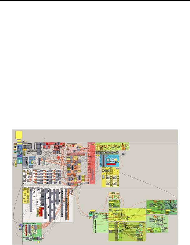
The algorithm (Fig. 1) includes three major stages: collecting and analyzing original design data, designing an architectural project based on processing the information and documenting the results in the form of a set of sketches.
Fig. 1. Algorithm for the author’s very own generative designing system for low-rise residential buildings
Let us look at the stages in more detail. 1. Working on the original data. One of the features of generative systems is maximum automation of collection of data necessary for starting a design followed by its further collection by means of an algorithm. In order to make this stage as
110