

Russian Journal of Building Construction and Architecture
.pdfRUSSIAN JOURNAL
OF BUILDING
CONSTRUCTION AND ARCHITECTURE
1

The journal is indexed/abstracted in:
Web of Science Core Collection
(Emerging Sources Citation
Index)
(Thomson Reuters), USA
Ulrich's Periodicals Directory
(Bowker), USA,
DOAJ
(Lund University), Sweden,
Academic Search Complete
(EBSCO), USA,
SOCOLAR
(China Educational Publications Import and Export Corporation –– CEPIEC), China,
Google Scholar
(Google), USA,
E-Library
(ООО «РУНЭБ), Russia,
J-Gate
(Informatics Ltd), India
2
ISSN 2542-0526
RUSSIAN JOURNAL
OF BUILDING
CONSTRUCTION AND ARCHITECTURE
N 4 (40)
BUILDING STRUCTURES, BUILDINGS AND CONSTRUCTIONS
BASES AND FOUNDATIONS, UNDERGROUND STRUCTURES
HEAT AND GAS SUPPLY, VENTILATION, AIR CONDITIONING, GAS SUPPLY AND ILLUMINATION
WATER SUPPLY, SEWERAGE, BUILDING CONSTRUCTION OF WATER RESOURCES PROTECTION
BUILDING MATERIALS AND PRODUCTS
TECHNOLOGY AND ORGANIZATION OF CONSTRUCTION
DESIGNING AND CONSTRUCTION OF ROADS, SUBWAYS, AIRFIELDS, BRIDGES AND TRANSPORT TUNNELS
BUILDING MECHANICS
ENVIRONMENTAL SAFETY OF CONSTRUCTION AND MUNICIPAL SERVICES
THEORY AND HISTORY OF ARCHITECTURE, RESTORATION AND RECONSTRUCTION OF HISTORICAL
AND ARCHITECTURAL HERITAGE
ARCHITECTURE OF BUILDINGS AND STRUCTURES. CREATIVE CONCEPTIONS OF ARCHITECTURAL ACTIVITY
CITY PLANNING, PLANNING OF VILLAGE SETTLEMENTS
FIRE AND INDUSTRIAL SAFETY (CIVIL ENGINEERING)
Voronezh 2018
3

Russian Journal
of Building Construction and Architecture
Periodical scientific edition
Published since 2009 |
Comes out 4 times per annum |
Founder and publisher: Federal State Education Budget Institution of Higher Professional Education «Voronezh State Technical University».
The articles are reviewed and processed with the program ANTIPLAGIARISM. This publication cannot be reprinted without the prior permission of the publisher, references are obligatory.
Number of the certificate of registration of the media ПИ № ФС 77-67855 Issued by the Federal Service for Supervision of Communications, Information Technology,
and Mass Media (Roskomnadzor)
Price is subject to change
EDITORIAL COUNCIL
The Head of the Council: Kolodyazhny S. A., D. Sc. in Engineering, rector (Voronezh State Technical University)
EDITORIAL BOARD
Editor-in-Chief: Melkumov V. N., D. Sc. in Engineering, Prof.
(Voronezh State Technical University)
Members:
Boldyrev А.М., Corresponding Member of the Russian Academy of Architecture and Engineering Science, D.Sc. in Engineering, Prof., Voronezh State Technical University, Russia
Bondarev B. А., D. Sc. in Engineering, Prof., Lipetsk State Technical University, Russia
Gagarin V. G., Corresponding Member of RAABS, Moscow State University of Civil Engineering, Russia
Gelfond А. L., Corresponding Member of the Russian Academy of Architecture and Construction Science, D. Sc. in Architecture, Nizhniy Novgorod State University of Architecture and Construction, Russia
Enin A. Ye., PhD in Architecture, Prof., Voronezh State Technical University, Russia
Karpenko N. I., Academician of RAABS, Research Institute of Building Physics (NIISF RAABS), Russia
Kirsanov М.N., D.Sc. in Physics and Mathemat-
ics, Professor (National Research University “Moscow Power Engineering Institute”)
Kobelev N. S., D. Sc. in Engineering, Prof., Southwest State University, Kursk, Russia
Kolchunov V. I., Academician of RAABS, Southwest State University, Kursk, Russia
Ledenyev V. I., D. Sc. in Engineering, Prof., Tambov State Technical University, Russia
Lyahovich L. S., Academician of RAABS, Tomsk State University of Architecture and Building, Russia
Mailyan L. R., D. Sc. in Engineering, Prof., Don State Technical University, Rostov, Russia
Panibratov Yu. P., Academician of RAABS, Saint Petersburg State University of Architecture and Civil Engineering, Russia PodolskyVl.P.,D. Sc. in Engineering, Prof.,Voronezh State Tech-
nical University, Russia (Dep. of the Editor-in-Chief)
SlavinskayaG.V.,D. Sc. in Chemistry, Prof, Voronezh State Technical University, Russia
SuleymanovА.М.,D. Sc. in Engineering, Prof.,Kazan State University of Architecture and Engineering, Russia
Fyedorov V. S., Academician of RAABS, Moscow State University of Railway Engineering, Russia
Fedosov S. V., Academician of RAABS, Ivanovo State Polytechnic University, Russia
Chernyshov Ye. M., Academician of RAABS, Voronezh State Technical University, Russia
Shapiro D. M., D. Sc. in Engineering, Prof.,Voronezh State Technical University, Russia
Shubenkov М. V., Academician of the Russian Academy of Architecture and Construction Science, D. Sc. in Architecture, Prof., Моscow Institute of Architecture (State Academy), Russia Asanowicz Alexander, Prof., Dr. of Sn., Technical University of Bialystok, Poland
Figovsky Oleg L., Prof., Dr. of Sn., Member of EAS, Israel Korsun V. I., D. Sc. in Engineering, Prof., The Donbas National Academy of Civil Engineering and Architecture, Ukraine Nguyen Van Thinh, Prof., Dr. of Sn., Hanoi University of Architecture, Vietnam
Editor: Kotlyarova E. S. |
Translator: Litvinova O. A. |
THE ADDRESS of EDITORIAL AND THE PUBLISHER OFFICE:84 20-letiya Oktyabrya str., Voronezh, 394006, Russian Federation Tel./fax: (473)2-774-006; e-mail: vestnik_vgasu@mail.ru
Publication date 15.11.2018. Format 60×84 1/8. Conventional printed sheets 14.53. Circulation 500 copies. Order 281.
Published in Printing Office of Voronezh State Technical University 84 20-letiya Oktyabrya str., Voronezh, 394006, Russian Federation
ISSN 2542-0526 |
© Voronezh State Technical |
|
University, 2018 |
4
CONTENTS |
|
HEAT AND GAS SUPPLY,VENTILATION, |
|
AIR CONDITIONING,GAS SUPPLY AND ILLUMINATION .......................................................... |
6 |
Isanova A. V., Martynenko G. N., Sedaev А. А. |
|
Optimization of Operation of a Heat-pump Facade System of Heating During Observance |
|
of the Required Parameters of Thermal Comfort of Residential Buildings............................... |
6 |
Makeev A. N. |
|
Theory of Pulse Circulation of the Heater in the Heat Supply System |
|
with Independent Subscription of Subscribers ...................................................................... |
15 |
Martynenko G. N., Kitaev D. N., Sedaev А. А. |
|
Prospects for the Development of the Gas Supply System of the city District of Voronezh |
|
for the Period Till 2035............................................................................................................ |
26 |
Petrikeeva N. A., Chudinov D. M., Kopytina Ye. A., Sotnikova O. A. |
|
Version of the Solution of the Problem of Optimization of Thickness |
|
of the Heat-Insulation Layer in Heat Supply ........................................................................... |
40 |
DESIGNING AND CONSTRUCTION OF ROADS,SUBWAYS, |
|
AIRFIELDS,BRIDGES AND TRANSPORT TUNNELS .................................................................. |
50 |
Zadiraka A. A., Kokodeeva N. Ye., Kochetkov A. V. |
|
Physical and Mechanical Properties of Polyurethane Crushed Stone for Slopes |
|
of Embankments and Excavations of Roads and Railways ................................................... |
50 |
Nosov S. V. |
|
Modeling the Evolution of Deformations and Stresses in Road-building Materials Based |
|
on Rheological Approach......................................................................................................... |
61 |
Podol'skii V. P., Al-Adddess M. X., Nosov S. V. |
|
Technology of Repair Works with Use of Emulsion-mineral Materials and Emulsions......... |
73 |
Podol'skii V. P., Popov A. N., Makarov E. V., Nosov S. V. |
|
Theoretical Basis for the Calculation of the Stress-Strain of a Repaired Airfield Coating...... |
85 |
BUILDING MECHANICS............................................................................................................ |
98 |
Poznyak E. V., Monin S. A. |
|
Statistical Modeling of a Dynamic Response of a Stadium Grandstand to Human Load ....... |
98 |
ARCHITECTURE OF BUILDINGS AND STRUCTURES.CREATIVE CONCEPTIONS |
|
OF ARCHITECTURAL ACTIVITY.............................................................................................. |
109 |
Fedchun D. O. |
|
A Comparative Analysis of the Methods of Generative, |
|
Parametric and Informational Architectural Design ............................................................. |
109 |
INSTRUCTIONS TO AUTHORS................................................................................................. |
123 |
5

HEAT AND GAS SUPPLY,VENTILATION,
AIR CONDITIONING,GAS SUPPLY AND ILLUMINATION
UDC696.48-67 : 621.577
A. V. Isanova1, G. N. Martynenko2, А. А. Sedaev3
OPTIMIZATION OF OPERATION OF A HEAT-PUMP FACADE SYSTEM OF HEATING DURING OBSERVANCE OF THE REQUIRED PARAMETERS OF THERMAL COMFORT OF RESIDENTIAL BUILDINGS
Voronezh State Technical University
Russia, Voronezh
1PhD in Engineering, Assoc. Prof. of the Dept. of Housing and Communal Services, tel.: (473)271-52-49, e-mail: a.isanova@bk.ru
2PhD in Engineering, Assoc. Prof. of the Dept. of Heat and Gas Supply and Oil and Gas Business, tel.: (473) 271-53-21, e-mail: glen2009@mail.ru
3D. Sc. in Mathematics and Physics, Assoc. Prof. of the Dept. of Applied Mathematics and Mechanics, tel.: (473) 271-53-62, e-mail: sed@vmail.ru
Statement of the problem. The influence of the speed of wind of areas inside backyards of urban multi-storeyed quarters on a decrease in thermal comfort in premises is considered. Loss of saved thermal energy affects an internal microclimate of structures. A drop of the temperature of the internal air of a part of a construction generally affects its thermal mode, which leads to an increase in the operational costs of maintaining the required parameters of the microclimate and deterioration of the indices of the power efficiency of a building.
Results. In order to maintain the acceptable parameters, a heat-pump system (HPS) of façade regulation is considered. The described model consists of two consistently connected thermal pumps and systems of sensors as well as two contours of a system of heating. During the operation of the equipmentthe excessthermalenergyforheatingof theroomslocatedon thesideofthebuildinglessexposed towindsgoes intothecolderpremisesfromthepartofthefacadewhich ismoreexposedtowinds.
Conclusions. The option for optimizing the operation of a HPS during consecutive connection of condensers is considered and parallel evaporators of thermal pumps for the consumption of the conditional fuel for smooth functioning of the system. Studies of the model of a heat-pump station where the efficiency of the first thermal pump exceeds that of the second one are presented. Their effect on the consumption of conditional fuel as a result of redistribution of thermal energy between premises on different facades of the building is investigated.
Keywords: thermal comfort, system of façade regulation, optimization of a heat pump, buildings with low energy consumption.
Introduction. In modern urban construction practice in the Russian Federation new residential areas mainly consist of high-rises, which is within investors’ interests but neglects com-
© Isanova A. V., MartynenkoG. N., Sedaev А. А., 2018
6
Issue № 4 (40), 2018 |
ISSN 2542-0526 |
fort levels. The fact that there is almost no greenery also has a negative impact on a wind mode of buildings. A rise in the speed of wind in the areas surrounding high-rises, an emerging wind tunnel effect around them contributes to blowing of accumulated heat of facilities on the along-wind side [8, 14, 15]. Therefore a reduction in the admissible parameters of the inside air of a part of a construction has an effect on its overall thermal mode and leads to an increase in energy costs for heating decreasing the energy-sustainable performance of a building.
The temperature and speed of the air is one of the major characteristics of microclimate of facilities [2, 7]. For the above conditions, the temperature and wind speed inside facilities will not be as specified in “The Set of Rules” (СП) 60.13330.2012, which will have a negative impact on heat comfort levels [12, 13, 16].
Studies of how to reduce heat losses in buildings and structures using a variety of methods are highly relevant [1, 7, 10, 12, 17, 19]. However, for a high-rise construction it is necessary that stitches of outside framing are hermetically sealed [17]. Wrong operation of framing and untimely maintenance leads to seal failures and considerable heat losses [18, 20]. The importance of the problem is that a heat pump system might facilitate an even distribution of heat inside residential structures. The suggested system of heat pump systems is instrumental in reducing the temperature of a heat-carrier that is needed to heat facilities on the along-wind side directing it for heating on the cross-wind side.
1. Statement of the problem. A reduction in loads on a heating system and maintenance of the required temperature parameters of the inside air is possible provided that a heat pump system is implemented. Using façade regulation in combination with heat pumps, a heat mode of facilities on the along-wind side of a building depending on deviations of the temperature of the air in a facility, changes in the temperature of the outside air, solar radiation onto the outside wall and effects of high-speed wind flows [1, 19]. The optimization of the operation of a heat pump system allows heating costs to be significantly cut.
A maximum effect from façade regulation should occur for quick and sufficient reactions of a system to changes in weather conditions: a drop in the water temperature in the supply heating system according to changes in loading. The opportunities offered by automatic sets of a system of façade regulation with a heat pump system allow algorithms of changes in the temperature of a heat-carrier inside the system to be employed, which is implemented in actual operation [6, 10]. An extra effect is achieved by using a system of façade regulation with thermostat sensors fitted in the heating equipment [4] (Fig. 1).
7
Russian Journal of Building Construction and Architecture
From the heating system |
|
Into the heating system located |
located at the along-wind façade |
|
at the along-wind façade |
|
|
|
Into the heating system located at the cross-wind façade
From the heating system located at the cross-wind façade
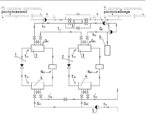
Fig. 1. Principal scheme of a HPS operating in conjunction with a system of façade regulation:
1 is a heat pump HP1; 2 is a heat pump HP2; 3 is a condenser; 4 is an evaporator; 5 is a network pump; 6 is a tank accumulator, 7 is a heat-exchanger; Qk is thermal load of the HP condenser, kWatt;
TO is the temperature of evaporation of the HP operating body, К; GH1 is the mass consumption of water in the heating system on the under-wind facade, kg/seс; GC is the mass consumption of water
in a heating system at the along-wind façade, kg/seс;
tH1, tH2 is the temperature of water at the input in the second one and at the output fromthe first HP evaporator, К; tB1, tB2 is the temperature of water at the input in the first and at the output of the HP condenser respectively, К; tK1, tK2 is the temperature of condensation of the HP1 and HP2 operating body respectively, К;
Т1 and Т2 is the temperature of a heat-carrier of a heating system at the along-wind façade before and after the HPS respectively
2. Use of a heat pump system. In this study a model of an individual heating spot of a heating system is that includes a façade system and two heat pumps. Condensers of a heat pump system are joined in a sequence and evaporators in parallel. The latter “pump” excess thermal energy that is needed for heating the windy or sunny side of the facade in order to supply heat to the alongand cross-wind sides of a building.
8
Issue № 4 (40), 2018 |
ISSN 2542-0526 |
The investigated system has two circulation contours and can be used in buildings with rectangular floor plan. An advantage of the described model is transformation of heat in a wider temperature range than the one suggested earlier [2, 13] as for each cycle of a heat pump an operating substance with the best properties in required ranges of change in the parameters.
Losses of a conditional fuel for the operation of a heat pump system are the main optimization criteria. The necessary operational parameters are chosen according to their smallest value [11]. The consumption of a conditional fuel of the system ВHPS, kg. t. c./f, [5, 9] is given by the formula:
|
В |
|
|
34.1 10 6(Т |
К |
1 |
Т |
О1 |
) |
|
с |
|
G |
(Т |
|
|
Т |
|
Т |
|
) |
|
|||||||||||
|
|
Э (1 |
|
|
|
|
|
Т |
|
|
|
1 |
К1 |
3 |
|
||||||||||||||||||
|
|
THС |
|
|
СН |
) |
Э.С. |
К1 |
Р |
|
C |
|
К |
|
|
|
|
|
|
||||||||||||||
|
|
|
|
|
K |
|
|
|
|
1 |
|
|
|
|
|
|
|
|
|
|
|
|
|
|
|
|
(1) |
||||||
|
|
34.1 10 6 ТК |
2 ТО2 |
|
|
|
|
|
|
|
|
|
|
|
|
|
|
|
|
|
|
|
|
|
|
|
|||||||
|
|
|
|
|
с |
|
|
G (Т |
К2 |
Т |
К2 |
Т |
К1 |
Т |
К1 |
), |
|||||||||||||||||
|
ЭK (1 |
СН ) Э.С. 2 |
|
ТК2 |
|
|
|||||||||||||||||||||||||||
|
|
|
|
Р |
|
C |
|
|
|
|
|
|
|
|
|
||||||||||||||||||
where TO1, TO2 is the temperature of evaporation of an operating body HP1 and HP2, К; TK1, TK2 is the temperature of condensation of an operating body HP1 and HP2 respectively, К; cp is a specific chosen isobar thermal conductivity of water, kJ/(kg∙К); TK2, TK1 is the final difference between the temperatures of an operating body and heat-carrier in the condenser HPS2 and HPS1 respectively, К; T3 is the temperature of water before the second condenser HP, К; GC are the mass consumption of a heat-carrier in a heating system, kg/sec; ЭK is the coefficient of efficiency at condensation electric power stations; φСН is the coefficient of own needs of an condensation electric power station; ηЭ. С. is the coefficient of efficiency of an electric network.
Let us accept that dimensionless temperatures of condensation of the operating body classified as corresponding evaporation temperatures in the evaporators HP1 HP2 and dimensionless complexes of constants [3] determined by the formula:
Х ТК1 /ТО1, |
Y TK 2 /TO2, |
|
||
aO 34.1 10 6CP , |
a1 |
ЭK ЭС 1 СН , |
(2) |
|
1 2 1 / 1, |
2 ТК2 ТК1 /ТО2, |
|||
|
||||
О ТО1 /ТО2, |
с1 ТК1 Т3 /ТО1, |
|
||
where ε1 is a relative difference of the coefficient of efficiency of HP1 and HP2; ε2 is a relative final difference of the temperatures in the HP condensers (to the evaporation temperature of the operating body in the HP evaporator); δО is a ratio of the temperatures of the operating body in the HP1 and HP2 condensers.
9
Russian Journal of Building Construction and Architecture
By introducing the transformations (2) into a dimensionless function of the total consumption of conditional fuel [6], we get:
|
U Х,Y |
|
2 a1 |
|
|
|
В X ,Y |
||
|
a T |
G G |
Г |
|
|||||
|
|
|
O O 2 |
|
C |
|
|
(3) |
|
|
O X O2 /Y 1 O X c1* O / X 1 O 1 c1* 1 o2 , |
||||||||
where |
c1* |
c1 1 1 , |
o2 |
2 |
/ o ; |
||||
the description of the function с1 is given in [6].
Let us conduct an analysis of the effect of the coefficient of efficiency of heat pumps joined into a system in the following way: the condensers in a sequence and evaporators in parallel. Let us consider that when condensers are joined in a sequence, final differences of the temperatures of a cooling agent and heat-carrier in each of them are almost equal. Let us evaluate a combination of values when a parameter of the heat transfer is 2 1 and a parameter of
the coefficient of efficiency 1 is within 1*,1 2 , i. е. the coefficient of efficiency of the
first heat pump is larger than of the second one.
As a result of the studies, an expression was obtained that determines the optimal temperatures of condensation of the HP operating bodies and making the following purpose function as small as possible:
|
|
|
|
|
|
|
|
|
X (3) |
|
|
|
|
|
|
A |
Y0(3) |
2 |
|
x1 |
|
|
|
2 |
x2 |
|
|
|
2 |
|
2 |
, |
|
|
|
|
|
|
|
|
|||||||||||||||||||||||||
|
|
|
|
|
|
|
|
|
|
|
|
|
|
|
|
|
|
|
|
|
|
|
|
|
|
|
|
|
|
|
|
|
|
|
|
|
|||||||||||||||||||||||||||||
|
|
|
|
|
|
|
|
|
|
0 |
|
|
|
|
0 |
|
0 |
|
|
|
|
|
|
|
|
||||||||||||||||||||||||||||||||||||||||
|
|
|
|
|
|
|
|
|
|
|
|
|
|
|
|
|
|
|
|
|
|
|
|
|
|
|
|
|
|
|
|
|
|
|
|
|
|
|
|
|
|
|
|
|
|
|
|
|
(4) |
||||||||||||||||
|
|
|
|
|
|
|
|
|
|
|
|
|
|
|
|
|
|
|
|
|
|
|
|
|
|
|
|
|
|
|
3 2 |
|
12 |
|
8 |
|
|
|
|
|
|
|
|
|
|
|
2 |
|
|
||||||||||||||||
|
|
Y (3) |
|
Y (3) |
2 |
|
|
|
|
|
|
|
|
2 |
|
|
|
|
|
|
0 |
|
|
|
|
|
|
2 |
|
, |
|
|
|||||||||||||||||||||||||||||||||
|
|
|
|
|
|
|
|
|
|
|
|
|
|
|
|
|
|
|
|
|
0 |
|
|
|
|
|
|
|
|
|
|
|
|
|
|
|
|
|
|
|
|
|
|
|
|
||||||||||||||||||||
|
|
|
|
|
|
|
|
|
|
|
|
|
|
|
|
|
|
(3) |
|
|
|
|
|
|
|
|
|
(3) |
|
|
|
|
|
|
|
|
|
|
|
|
|
(3) |
|
|
|||||||||||||||||||||
|
|
|
|
|
|
|
|
0 |
|
|
|
|
|
A |
|
|
|
Y |
|
|
|
|
|
|
|
|
Y |
|
|
|
|
|
|
|
|
A |
|
Y |
|
|
|
||||||||||||||||||||||||
|
|
|
|
|
|
|
|
|
|
|
|
|
|
0 |
|
|
|
|
|
|
|
0 |
|
|
|
|
|
|
|
|
|
|
|
0 |
|
|
|
|
|
||||||||||||||||||||||||||
|
|
|
|
|
|
|
|
|
|
|
|
|
|
|
|
|
|
|
|
|
|
|
|
0 |
|
|
|
|
|
|
|
|
|
|
0 |
|
|
|
|
|
|
|
|
|
|
|
|
|
|
0 |
|
|
|
||||||||||||
where |
x |
1 |
4 |
|
; |
|
x |
2 |
|
A Y (3) |
|
|
|
3 |
|
|
2 |
; |
|
|
|
|
|
Y 3 |
4 B*3 |
; B3 |
|
2 |
c |
; |
|||||||||||||||||||||||||||||||||||
|
|
|
|
|
|
|
|
|
|
|
|
0 |
|
|
|
|
|
|
0 |
|
|
|
|
|
|
|
|
0 |
|
|
|
|
|
|
|
|
|
|
1 |
|
|
|
0 |
1 |
|||||||||||||||||||||
|
|
|
|
|
|
|
c* |
|
|
|
|
|
|
|
|
|
|
|
|
|
|
|
B*3 |
|
|
||||||||||||||||||||||||||||||||||||||||
|
1 |
|
0 |
|
|
|
2 |
|
|
|
|
|
|
|
|
0 |
|
|
|
|
3 |
|
|
|
|
|
|
0 |
|
|
|
|
|
|
|
|
|
|
|
|
|
1 |
|
A2 |
|
||||||||||||||||||||
|
|
|
|
|
|
|
|
|
|
|
|
|
|
|
|
|
|
|
|
|
1 |
|
|
|
|
|
|
|
|
0 |
|
|
|
|
|
|
|
|
|
|
|
|
|
|
|
|
|
|
1 |
|
|
|
|
|
|
|
|
|
|
||||||
Q 1 23 4 B1 1 |
|
|
1 1 K K ; |
|
K |
1 3 1 |
1 |
|
4 |
3 |
4 |
|
3 |
|
|
|
|||||||||||||||||||||||||||||||||||||||||||||||||
|
|
|
|
3 |
B1 |
13 1 1 ; |
|||||||||||||||||||||||||||||||||||||||||||||||||||||||||||
|
|
|
|
|
|
|
|
|
|
|
|
|
|
|
|
|
|
|
|
|
|
|
|
|
|
|
|
|
|
|
|
|
|
|
|
|
|
|
|
|
|
|
|
|
|
|
|
|
|
|
|
|
|
|
|
|
|
|
|
|
|
|
|||
|
|
(2) |
|
|
|
1 |
4 |
|
Q |
|
|
|
|
|
|
|
|
|
|
|
2 |
|
Q |
|
|
|
|
|
|
(2) |
|
|
|
|
A |
|
|
|
|
|
|
|
(2) |
2 |
|
|
|
|
|
|
|||||||||||||||
|
|
|
|
|
|
|
|
|
|
|
|
|
|
|
|
|
|
|
|
|
|
|
|
|
|
|
|
|
|
|
|
|
|
|
|
|
|
|
|
|
|
||||||||||||||||||||||||
|
|
Y0 |
|
|
|
|
|
|
|
|
|
|
1 |
|
|
|
|
|
|
|
|
|
|
|
|
|
|
; |
X |
0 |
|
|
|
|
|
|
|
Y0 |
|
|
|
; |
|
|
|
|
|
||||||||||||||||||
|
|
|
|
|
4 1 |
|
|
|
|
|
|
|
|
Q |
|
|
|
|
|
|
0 |
|
|
|
|
|
|
|
|||||||||||||||||||||||||||||||||||||
|
|
|
|
|
|
|
|
|
|
|
|
|
|
|
|
|
|
|
|
|
|
|
|
|
|
|
|
|
|
|
|
|
|
|
|
|
|
|
|
|
|
|
|
|
|
|
|
|
|
|
|
|
|||||||||||||
|
|
|
|
|
|
|
|
|
|
|
|
|
|
|
|
|
|
|
|
|
|
|
|
|
|
|
|
|
|
|
|
|
|
|
|
|
|
|
|
|
|
|
|
|
|
|
|
|
|
|
|
|
|
|
|
|
|
|
|
|
|
|
|
||
|
|
Y0(3) |
|
3 |
4 |
|
B1* |
|
|
|
|
|
|
|
|
|
K K |
|
|
; |
|
|
|
X0(3) |
|
|
A |
Y0(3) 2 . |
|
|
|
|
|
||||||||||||||||||||||||||||||||
|
|
|
|
4 Q |
|
|
4 Q |
|
|
|
2 |
|
Q |
|
|
|
|
0 |
|
|
|
|
|
||||||||||||||||||||||||||||||||||||||||||
|
|
|
|
|
|
|
|
|
|
|
|
|
|
|
|
|
|
|
|
|
|
|
|
|
|
|
|
|
|
|
|
|
|
|
|
|
|
|
|
|
|
|
|
||||||||||||||||||||||
The function с1, А is described in [6].
10