

2900
.pdfThe program has converted the circuitry in the box region into a macro circuit. To do this it did the following:
1.Placed the circuitry within the box region in a file called ECLGATE.MAC.
2.Placed an ECLGATE macro into the current component library.
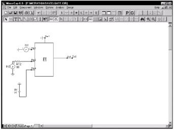
3.Modified the ECLGATE circuit on the screen by replacing the contents of the region box with a macro call ECLGATE.
As a result of this action the ECLGATE circuit appears simpler. Its complexity is hidden and encapsulated in the macro block called ECLGATE. In addition the macro has been entered into the component library and is available for use by other circuits.
You can see the macro circuit by clicking on the Info I | button and then clicking on the ECLGATE macro block. It looks like this:
Figure 11-8 The ECLGATE macro circuit
The program has determined that five pins are needed and has located the pin text as required. This form of macro creation always uses an adjustable macro box. Its sides and pins can be moved about as desired. It always retains its rectangular shape, however.
88
To change the location of the pins, select the macro by clicking on it. Drag the dot at the end of the pin to the new location and release it. To change the shape of the macro box, select the macro by clicking on it. Drag a corner dot to change both length and width. Drag a side dot to change length or width. For example, the figure below shows an example of how the shape can be modified. Compare this with Figure 11-7.
\
Figure 11-9 The altered macro box shape
89

Задание 7
Прочтите и ответьте на вопросы.
1.Чем SPICE-блоки отличаются от макросов?
2.Поясните процесс создания файла описания SPICEблока и назначения ему визуального представления?
3.Как внести SPICE-блок в библиотеку компонентов?
4.Опишите практическое применение SPICE-блоков.
5.Как определить назначение контактов схемы?
Chapter 12 Working with Subcircuits
What's in this chapter
This chapter describes the use of SPICE subcircuits. The four steps of subckt creation and usage are described. They are:
•Creating the subckt circuit file
•Selecting or creating a suitable shape for the subckt
•Entering the subckt into the Component library
•Using the subckt in a circuit
What is a subcircuit?
Subcircuits are complete SPICE text file circuits, created and saved on disk to be used by other circuits. The great virtue of subcircuits is the same as for macros; the behavior of a complex circuit block can be incorporated into and represented by a single component. The complexity and detail is hidden from view in the circuit that uses the macro. Another major advantage is that many manufacturers create SPICE subckt models for their parts. Access to these models is the key reason for using subcircuits.
90
Creating the subcircuit text file
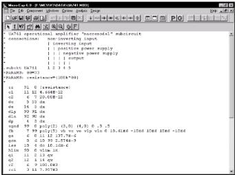
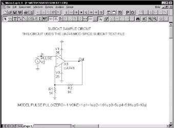
The first step is to create the subcircuit circuit itself. We won't do that here. Instead we'll use an existing subcircuit, supplied with MC6. To load the SPICE file, select the Open item from the File menu. Type "UA741.MOD". The circuit file looks like this:
Figure 12-1 The UA741.MOD subcircuit
This subcircuit is a standard Boyle-type model for the classic UA741. The circuit file can be created with the MC6 SPICE text editor or by using an external word processor. Frequently, it can be obtained as a text file from a manufacturer of the part. Once obtained, it need only be saved in the data directory and the file name entered into the "NOM.LIB" file to be accessible to MC6. The file name is entered by adding a line such as,
.LIB "UA741.MOD"
to the NOM.LIB file. The NOM.LIB file is located in your data directory.
91
Selecting a suitable shape for the subcircuit
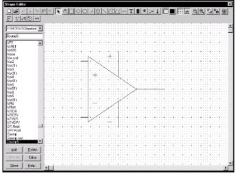
The second step is the selection or creation of a suitable shape. Select the Shape Editor from the Windows menu. For our example, the opamp5 shape will do nicely. It looks like this:
Figure 12-2 The opampS shape
If there are no suitable shapes in the library, you can create a new one to visually suggest the function of the subcircuit. All shapes created are added to and appear in the Shape list field of the Component editor.
Putting subcircuits into the Component library
The third step is to enter the subcircuit in the Component library. To do this, select Component Editor from the Windows menu. Double-click on the Subckts group of the Analog Primitives group. This presents a list of the existing subcircuits. Click on Opamp_ subckt_5. This selects and shows the existing Opamp_subckt_5
92
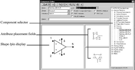
component. If you were adding this component as a new subcircuit you would have clicked first on the Subckt group to select it, then clicked on the Add Component button to add the Opamp_subckt_5 component to the macro group and edited the data fields to look like these:
Figure 12-3 The subckt Component library entry
The first data field is the Component name. This can be any alphanumeric name. It does not need to be the name of the subckt. In this case we used the general name, Opamp_subckt_5, but we could also have chosen the name UA741.
The Shape entry is the name of the shape to be used to represent the macro. Here we have selected the opamp5 shape. Click on the down arrow to see a list of the available shapes from the Shape library.
The Definition field is where you specify the electrical definition. In this case, we specify Subckt. Click on the down arrow to see a list of the available definitions.
The Attribute placement fields define the location of the attribute text (XX and YY in Figure 12-3) relative to the shape. Subckt
93
attribute text is comprised of the PART attribute which provides the part name, the NAME attribute which specifies the name of the subcircuit, the FILE attribute which specifies the name of the file containing the .SUBCKT statement, the PARAMS attribute which provides any passed numeric parameters, and the TEXT attribute which provides any passed text parameters. These attributes are specified when the component is placed in a schematic. The Attribute placement fields let you drag the text with the left mouse button to define where the first (XX) and second (YY) attribute text will be initially placed. After the component is placed, attribute text can be relocated by dragging with the mouse.
An important aspect of entering a subckt into the library is defining where the pins are. For a component like a BJT, the pin names are predefined as Emitter, Base, and Collector. For a subckt, the pin names and locations must be defined by the user. This is done by clicking in the Shape / pin display field. This activates a Pin dialog box, allowing you to enter a new pin name and to specify if it is digital or analog. Double-clicking on an existing pin lets you edit it. Both the pin marker dot and the pin name can be independently dragged with the mouse to the desired locations.
The pin names used in the Component library must match those in the .SUBCKT statement in the file that contains the subckt itself. For example, the UA741 uses 1 as the name of the positive input pin, so we need a pin named 1 at the position on the shape we want to identify as the positive input pin. Similarly, 5 is used as the name of the output pin so we want to have a pin named 5 placed on the shape where we expect to find the opamp output.
UA741 Subckt Pin Names |
Description |
1. |
Positive input pin |
2. |
Negative input pin |
3. |
Positive power pin |
4. |
Negative power pin |
5. |
Output |
|
94 |
Notice that you could put the pins anywhere. There is nothing magic about placing the positive input pin near the + symbol. It is simply easier to remember where the pins are when you wire them into a circuit.
Close the dialog box.
Using the subcircuit as a component
The final step is using the subckt. Once it has been entered into the Component library, it is available for use in any circuit and can be accessed from the Analog Primitives / Subckt group on the Component Menu. Unload the UA741.MOD SPICE file and load the SUBCKT1 circuit. It looks like this:
Figure 12-4 Using the subckt component
The key points about using a subckt are:
1. The subckt is usually selected from the Analog Primitives / Subckts, the Analog Library, or the Digital Library areas of the Component menu.
95
2.MC6 searches for the subckt in the following places:
• The text area of the schematic.
• The file listed in the File attribute.
• The files in any .LIB statements, including the default .LIB NOM.LIB. Priority is given to a user defined .LIB statement over the NOM.LIB.
3.Many different subcircuits can be covered with a single, generic subckt entry in the Component library, if they share the same pin count and node order.
96

Задание 8
Прочтите и ответьте на вопросы.
1.Какие данные (результаты) можно распечатывать в графическом режиме ?
2.Какие сведения печатаются в текстовом режиме?
3.Поясните управлением масштабом при распечатке схем?
4.Расскажите, как осуществляется печать результатов моделирования.
Chapter 13 |
Printing |
What's in this chapter
This chapter describes how to get copies of your work on printers. MC6 provides output in two basic ways.
Graphics:
•Schematics
•Analysis plots
•Performance plots
•3D plots
•Monte Carlo histograms
Text:
•Schematic text area
•SPICE circuit descriptions
•Document files
•AC, DC, and transient analysis numeric output
•Transient analysis state variables
•Monte Carlo statistics
All text output is available in disk file or hard copy form. Graphics output is available on any printer that your system supports.
97