

m0931
.pdf31
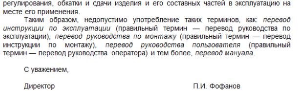
Упражнение 3. Деловая игра «Запрещенные “мануалы”». Директор переводческого агентства «Тема и рема» раздал начинающим переводчикам следующую информационную листовку. Изучите ее содержание. Определите, какой текст является а) руководством по эксплуатации, б) руководством оператора, в) инструкцией по монтажу изделия. Переведите предложенные тексты на русский язык.
32
(1)
This manual, the design and ideas shown herein, and any copies made from this document are confidential and proprietary information of Rader Companies, Inc., Rader Canada, and Rader AB. It is to be returned on request. This manual, designs, and ideas shown herein shall not be used, copied, or disclosed to others, in whole or in part, either in written or electronic form, without the prior written permission of Rader Companies, Inc. These restrictions are in addition to and not in lieu of any other confidential / non-disclosure restrictions owed to Rader Companies, Inc.
A. Overview and General Safety A.1. Preface
This manual is provided as a guide to personnel involved with the installation, operation, and maintenance of Rader equipment. Operators, Inspectors, and Maintenance personnel of Rader equipment should read and become familiar with the general procedures and information contained within this manual. In addition we recommend that this manual be kept readily available for reference before beginning any work associated with equipment.
Safety precautions and instructions for awareness and information on potential hazards are found throughout this manual. Due to the complexities of the systems in which this equipment is used and the environment in which it operates, situations may arise which are not directly discussed in detail in this manual. When such a situation arises, past experience, availability of equipment, and common sense play a large part in what steps are to be taken. In addition, a Rader service representative is available to answer your questions, perform inspections and safety reviews, provide operator training, and supervise maintenance crews upon request.
Please feel free to contact a Rader representative at the following Rader office locations. Additional contact information can be found on the Internet at WWW.RADER.COM.
A.2. General Safety
All parts of the equipment and the system into which it's installed must be used in keeping with sound safety practices. This manual contains safety information designed to be used in two ways: first as a primary reference for operators and mill maintenance personnel, providing them with details and explanations of operational and maintenance safety procedures; and second as a training tool within your mill's safety program.
Safety begins with properly designed and manufactured equipment. To that end, Rader has designed this equipment with safety in mind. However, the use of the equipment is subject to certain hazards that cannot be met by mechanical means alone, but only by the exercise of intelligence, care, and common sense. Once the equipment enters service, Rader has no direct control over its inspection, maintenance, or operation. For this reason, safety in the field is the responsibility of the user.
(2)
6.7 «CO2 Liquefaction» из «Trainings manual-CO2 Recovery Systems»
Haffmans B.V.-VENLO/HOLLAND
6.7 CO2 Liquefaction 6.7.1 General Description
The basic configuration of every cooling system consists of a refrigerant compressor (later referred to as the cooling compressor), a refrigerant condenser and a refrigerant evaporator (later referred to as the CO2 condenser) as is schematically shown in figure 12. Sometimes one or more parallel components may be installed.
Depending on the refrigerant type, the available utilities, the purification requirements and the consumer preferences, the cooling plant can be configured in a number of ways. The cooling plant configuration for your CO2 installation is outlined in the system specification of the operation manual.
33
First the Refrigerant compressor will be discussed, including the oil separator and the oil cooler. Then the refrigerant condenser will be described. Finally the CO2 condenser is discussed.
Figure 12. Schematic representation of the cooling system
6.7.2 Cooling compressor
The cooling compressor compresses the low pressure refrigerant gas from the CO2 condenser and delivers high pressure gas to the refrigerant condenser. The refrigerant gas is continuously recycled in the system.
(3)
4.1 Mounting the compressor
The accessible hermetic compact screw compressors provide a motor compressor unit. It is only necessary to mount the complete unit correctly and to make the electrical and pipe connections.
With stationary systems the compressor has to be installed horizontally. In case of marine application a definite diagonal mounting in direction of the longitudinal axis of the boat may be required. Detailed layout recommendation if requested.
Anti-vibration mountings
Rigid mounting of the compressor is possible. The use of anti-vibration mountings especially matched to the compressors (accessory) is recommended however to reduce the transmission of body radiated noise.
With mounting on shell and tube heat exchangers:
Attention! Do not mount the compressor solidly on the heat exchanger. Do not use the heat exchanger as load-carrier!
Damage of the heat exchanger is possible (vibration fractures). Use anti-vibration mountings!
The installation of the anti-vibration mountings is shown in figure 7. The screws should only be tightened until slight deformation of the upper rubber disc is just visible.
Упражнение 4. Секретарь переводческого агентства «Тема и рема» оставила в приемной папку с разными документами для перевода. Вам поручен перевод следующей технической документации: а) спецификации, б) технического задания, в) накладной, г) договора и д) сметы. Выберите из папки эти тексты и переведите их на русский язык.
(1)
ELECTRIC CEMENT MIXER SAFETY INSTRUCTIONS
Read and understand these instructions before using this equipment. Safety Instructions for this Equipment
Ensure all guards are in place before operating machine. Never attempt to lock the switch in the ON position with tape or by any other means. Always disconnect from the power supply when changing any fittings or cutting tools or leaving the machine unattended.
Clear work area of all obstructions, and ensure you have a firm foothold. Take care to keep the power cord away from any moving head or cutting tool.
Keep hands, feet and loose clothing away form all moving parts of the machine. Warning: Prolonged use of hand operated equipment exposes the user to vibrations.
Users should stop using this machine if they feel numbness or inability to feel temperatures.
Safety Equipment
The following protective equipment MUST be worn when using this equipment: Leather boots preferably with steel caps.
Close fitting clothing.
Electrical Safety
Never use the tool in damp or wet places, and never expose them to rain unless specifically designed for that purpose.
Do not handle the plug or unit with wet hands.
Do not use the tool in the presence of flammable liquids or gases unless specifically designed for that purpose.
Never carry tool from the cord or yank it to disconnect from receptacle. Keep cord from heat, oil and sharp edges. Never use the machine if the cord is cut, cracked, worn or damaged.
Never risk unintentional starting when plugging in the tool. Confirm the switch is in the OFF position before inserting the power plug in the receptacle.
Do not touch movable parts or accessories unless the power source has been turned off. Always disconnect the tool before changing accessories.
34
When not in use, tools should be stored, place out of reach of children. Never lock switches in 'ON' position with tape, wire or by any other means.
REMEMBER: In the event of death, serious injury or a dangerous occurrence you must notify WorkCover on 181800 136 089
|
(2) |
SLITTING & REWINDING MACHINES (SLITTING REWINDERS). |
|
MRB-0 MAIN TECHNICAL PARAMETERS: |
|
Rewinding Material |
Cable paper, semiconducting paper, telephone cable |
|
paper, Films PET, PP, PE, nonwoven materials |
Slitting film thickness |
0,012…0,2 mm |
Slitting paper thickness |
0,05…0,3 mm |
Unwinding Width |
500…1300 mm |
Max. Unwinding Diameter |
1000 mm |
Inner diameter of unwinding paper core |
76,0 mm |
Max. Rewinding Diameter |
500 mm |
Inner diameter of rewinding paper core |
76,0 mm |
Min. Slitting width |
10 mm |
Max. Slitting speed |
450 m/min |
Power supply: |
3P 380V/50HZ |
Pneumatic system: compressed air |
0,55…0,6 MPa |
Max. installed capacity |
26,4 kW |
Rewinding diameter precision |
±2 mm |
Rewinding length precision |
±0,5 m |
Take-up shafts quantity |
2 |
Unwind lift system |
hydraulic |
Pay-off Roll edge controller |
Automatic |
Slitted edge removal device |
Aspiration system |
Slitting method |
circular cutter |
Material Break controller |
Automatic |
Net Weight |
5500 kg |
Overall Dimensions, mm: |
1854(H)х2300(L)х2884(W) |
Tension control system |
Automatic |
|
(3) |
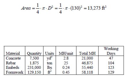
The ratio of the material to concrete, multiplied by the amount of concrete gives the quantity of material needed for the construction of the walls inside the reactor building. Using these values, the total man-hours needed for construction of each material is calculated. Given the dimensions of the reactor building above, the cross-sectional area of the building is:
Assuming that an average worker requires 300 square feet of space to work, then work in containment is limited to 45 workers. Therefore, it will be assumed that the crew working on the SC structures consists of about 45 workers. Assuming a work day of 10 hours, the total number of working days to complete the SC structures for each material is also given in Table N-5.
Table N-5. Total Man Hours and Working Days for Each Material
35
(4)
Object
The object of the given agreement is the right to hold the patent to application 200/1000, (hereinafter Patent), recognized as its rightful patent holder Ivanov V.V. in Russian Bureau 1.01.2000.
Invention contents: gas sensor that may be used to measure gas pressure in different tubes, hereinafter G_S. The invention description and patent addendum must comprise the Addendum of the given Agreement. The Seller must present the Buyer with all materials related to know-how patenting and all corresponding documentation on signing the Agreement.
Subject of agreement
The Seller hands over to the Buyer his rights to own the Patent on the agreed territories, including the right to conduct patent registration no later than 1.01.2001, based on the Patent privilege stated above.
Territory
The Buyer has the right to gain all rights of ownership and registration on the Patent in any country except Russia, where the Seller remains the Patent owner.
Special Conditions
The Buyer is aware that the Seller, as the sole patent holder, is also the Patent author and has coauthors. The Seller states that he is acting on behalf of the copyright agreement and will independently fulfill his obligations before the coauthors.
After the Buyer’s registration of R_R invention on the agreed territories, the Seller retains copyright to
R_R invention. All ownership rights on the invention registered by the Buyer, that come as a result of cooperation, belong to the Buyer under condition that the Buyer informs the Seller about the fact of registration, and identifies him as one of the coauthors of future inventions that are based on R_R.
(5)
36
(6)
The cryogen air separation plant control system should be supplied together with air separation plant including instrumentation and control system. Automation devices and means should provide flexibility of inputs of technological modes of operations and should have required safety control level. Air separation control system should represent integral, fully programmed, tested control and technological process management system. Control system should insure control and status visualization of all technological processes with events archiving. The final equipment set should be agreed during contract execution. The system should have the possibility to expand capacity for upgrading of a system and for technological process modernization or its separate mechanisms and should have 15 % of reserve from installed inputs and outputs of each type and 10% cabinets reserve to install additional units.
Automation monitoring and control system of air separation plant should insure:
–automation switch of complex air treatment block absorbers;
–plant technological parameters measuring and control, prealarm and warning alarm (light and sound) of technological set parameters deviation;
–main parameters stabilization by means of automatic control circuit;
–plant driving units remote control;
–technological equipment automatic protection;
–automatic blocking which prevent emergency situations;
–plant control system should insure the communication with control systems of compressor, of cooling machine, of electrical pump unit and of water electric pump units, of storage and gasification system, of oxygen distribution center, of pump station. Dialog windows and local systems menus should be in Russian.
Operator-technologists working stations should have PCs. PCs should:
–display plant process graphic and units process graphics and other information configurated in suitable combinations;
–changeable and other archives running on magnetic medium with further print out;
–warning for operators if the technological mode is not correct.
Automation monitoring and control system should insure the distance for operator’s station from blocks and plant units up to 300 m on communications links.
37
(7)
(8)
The milestone table shows how the responsibilities break down in the start up of our store. Ted Brinkman will head up the drafting of the business plan and will conduct the drive to secure funding. Jim Spencer will work to secure a site for the store and will handle the details with the personnel plan. Our accountant Dick Garret will set up our accounting plan.
38

Milestones |
|
|
|
|
|
|
Milestone |
Start |
End Date |
Budget |
Manager |
Department |
|
Date |
||||||
|
|
|
|
|
||
Business Plan |
1/1/2003 |
2/3/2003 |
$1,000 |
Brinkman |
Owner |
|
Secure Start Up |
2/17/200 |
4/3/2003 |
$500 |
Brinkman |
Owner |
|
Funding |
3 |
|
|
|
|
|
Site Selection |
3/1/2003 |
4/22/2003 |
$1,500 |
Spencer |
Management |
|
Personal Plan |
6/4/2003 |
6/21/2003 |
$500 |
Spencer |
Management |
|
Accounting Plan |
7/8/2003 |
7/19/2003 |
$1,000 |
Tollman |
Accounting |
(9)
|
CERTIFICATE |
|
MARRIAGE CERTIFICATE |
Mr. |
Ivanov |
|
(last name) |
|
Ivan Ivanovich |
|
first name and patronymic name) |
|
date of birth 18.02.1978 |
|
(place of birth) |
|
city of Izhevsk |
and Ms. |
Petrova |
|
(last name) |
|
Anna Petrovna |
|
first name and patronymic name) |
|
date of birth 23.11.1979 |
|
(place of birth) |
|
city of Izhevsk |
have entered into marriage on 03.06.2000
in witness whereof a record number #000
was made in the Register on 00.00.0000
After the marriage the following last names
were given: |
|
to husband: |
Ivanov |
to wife: |
Ivanova |
Place of registration: Vital Statistics Office
city of Izhevsk, the Udmurt Autonomous Soviet Socialist Republic
(name and address of the Vital Statistics Office) Stamp: Vital Statistics Office Bureau
Executive Committee of the Izhevsk city Municipal Soviet
date of issue: |
15.06.2000 |
39

(10)
40