

Geomagnetic_Disturbance_Task_Force_2012
.pdfChapter 8–Power System Analysis
Request manufacturers to evaluate the GIC flows vs. Load Capability of the transformer design for high peak levels of short duration GIC pulses as well as moderate levels of long duration GIC flow levels. Use these characteristics for the operating procedures.
Specify heating sensors in critical parts of the transformer.
Specify a larger margin in overcurrent withstand of shunt capacitor banks.
Specify full rms overcurrent capacitor bank protection.
Enable operator triggered forced cooling on transformers as a standard operational measure on GMD events K7 or higher (or direct GIC measurement or transformer
temperature if available). This would buy some lead time by operating transformers at lower pre event temperatures.110
Poll harmonic monitoring on IEDs used in transformer differential protection. This is an indirect but simple way to monitor the level of GIC on transformers regardless of type and construction
8.8Conclusions
The combination of increased reactive power absorption and injected harmonics into the system by saturated transformers, changes the worst case scenario due to a low probability, high magnitude GMD event, to one of voltage instability and subsequent voltage collapse. Reactive power absorption from saturated transformers would tend to lower system voltages. Tripping of reactive power support from capacitor banks and SVCs due to high harmonic currents at a time when the saturated transformers increases the VAr demand, creates the scenario for voltage collapse. This is exactly what triggered the 1989 Hydro Québec blackout.
Planners and operators require the technical tools to model GIC flows and develop mitigating solutions, as necessary. The development of these tools includes a combination of GIC flow calculations for a variety of system conditions and configurations, test wavefronts representative of GMD events for a variety of latitudes and ground conductivity structures, and suitable thermal equipment models.
8.9References
[1]D. H. Boteler, R. J. Pirjola, “Modelling Geomagnetically Induced Currents Produced by Realistic and Uniform Electric Fields,” IEEE Transactions on Power Delivery, vol. 13, no. 4, October 1998, pp. 1303 1308.
[2]Bolduc, L.; Langlois, P.; Boteler, D.; Pirjola, R., “A study of geoelectromagnetic disturbances in Quebec. I. General results “, IEEE Transactions on Power Delivery, Volume: 13 , 1998 , pp. 1251 – 1256.
[3]X. Dong, Y. Liu, J. G. Kappenman, “Comparative Analysis of Exciting Current Harmonics and Reactive Power Consumption from GIC Saturation Transformers,” IEEE Power Engineering Society Meeting, 2001, pp. 318 322.
110 Static Electrification occurs when electrons are stripped away from the oil as it rubs on the winding insulation pressboard washers as the oil passes through the oil ducts at a high velocity, caused by forced cooling.
Effects of Geomagnetic Disturbances on the Bulk Power System–February 2012 |
69 |

Chapter 8–Power System Analysis
[4]L. Marti, J. Berge, and R. K. Varma, "Determination of Geomagnetically Induced Current Flow in a Transformer from Reactive Power Absorption", Submitted to IEEE Transactions on Power Delivery
[5]Investigation of Geomagnetically Induced Currents in the Proposed Winnipeg Duluth Twin Cities 500 kV Transmission Line, EPRI EL 1949, July 1981.
70 |
GMDTF Interim Report: Affects of Geomagnetic Disturbances on the Bulk Power System–February 2012 |

Chapter 9–Grid Monitoring Enhancement
9.Grid Monitoring Enhancement
9.1 Introduction
An essential part of a GIC flow mitigation program is to install monitors to measure GIC flow and harmonics on a continuing basis. Monitors are a key source of real time information that can guide system operators in determining real time response. The monitors can also provide valuable historical records of previous storm activity that can be evaluated and factored into power system planning and analysis. Coupled with alerts and warnings that may be issued by the SWPC or CSWFC, the monitoring data can provide the reinforcing message that a GMD event is imminent or in progress and can spur action.
In order to mitigate the risk of GMD events impacts on power grids, installation of monitors is recommended to detect and evaluate GIC and harmonics at multiple locations. The placement of the monitors is influenced by a number of vulnerability factors, including system topology, local geology, transformer type, etc. A GIC flow and harmonics monitoring system can provide additional information to help system operators evaluate imminent risk to transformers due to GIC and take appropriate actions, preventing equipment damage and system blackout.
Attachment 6 provides an example of monitoring systems from an asset owner’s perspective. The monitoring system comprises both the monitoring of GIC flows and harmonics. GIC flows, second and fifth harmonics, MVAr, MW, and voltages on key transformers should be monitored, as well as the rate of change of these variables. The Kp index provided by the space weather forecasters should also be documented for post event correlation analysis.
9.2 GIC Flow Monitoring
The GIC flow monitoring system includes a Hall effect DC current transducer and a GIC relay. GIC data can be passed from the transducer by GIC relay via fiber to a remote terminal unit (RTU) in a control house.
9.2.1 Hall-Effect DC Current Transducer
The DC current transducer is a Hall effect sensor integrated with an output amplifier. The DC
sensor should accommodate at least +/ 500 amps of DC current with an extended temperature
range.111,112
The Hall effect sensor is available in different sizes for different applications. Appropriate sensor size must be chosen to fit transformer neutral insulated cables. Additionally, Hall effect transducers should be tested for accuracy, including conducting tests on temperature measurement accuracy and measuring DC with an AC background.
111A DNP 3.0 protocol can be used to meet NERC Critical Infrastructure Protection (CIP) requirements, and a 0.5% resolution will be required over a 40 ~ 60°C temperature range.
112Normally the standard outputs of the DC transducer can be either AC/DC current (e.g., 4 ~ 20 mA) or DC voltage (e.g., +/ 5 V DC or +/ 10 V DC). +/ 10VDC output is preferable if it is fed into a GIC relay.
Effects of Geomagnetic Disturbances on the Bulk Power System–February 2012 |
71 |

Chapter 9–Grid Monitoring Enhancement
9.2.2 GIC Monitoring System Installation
For a typical GIC installation, a DC transducer cabinet and a GIC relay cabinet are added to the existing transformer neutral structure. The GIC relay cabinet connects to an RTU and/or a local substation computer.
9.3 Harmonics Monitoring
In order to minimize hardware/installation cost associated with harmonics monitoring, using existing transformer protection intelligent electronic device relays to provide harmonics information is preferable. If the existing transformer protection uses old electromechanical relays, such as BDD relays, a standalone harmonics monitoring device can be installed to monitor harmonics, MVAr, MW, voltage, etc. Some devices can provide harmonics monitoring to the 50th order. Oscillography waveforms can also be captured from a transformer relay triggered by the GIC level. The waveforms can be stored in the local computer for post event analysis.
A visualization and decision tool is needed to help operators implement appropriate actions based on a combined GMD event index, which can comprise the following monitoring data:
GIC flows
Harmonics
Rate of MVAr changes
Transformer temperature rise
GMD forecast
Alarm displays should be developed based on different trigger thresholds of the combined GMD index. Transformer subject matter experts and vendors should be consulted to develop an algorithm for appropriate alarm triggers. Operating procedures can be enhanced and refined based in part on the combined GMD index.
72 |
GMDTF Interim Report: Affects of Geomagnetic Disturbances on the Bulk Power System–February 2012 |

Chapter 10–GIC Reduction Devices
10. GIC Reduction Devices
10.1 Introduction
A number of mitigation approaches can be used to address those transformers viewed to be vulnerable to failure, as well as their criticality to system operation. One mitigation approach involves the installation of neutral current blocking devices on transformers that are designed to block or impede the flow of GIC (quasi DC) where the current couples to the power system. Neutral blocking philosophy has been researched and tested by EPRI.113 In addition, similar transformer neutral devices have been installed elsewhere in the industry for GIC mitigation and other operational conditions.
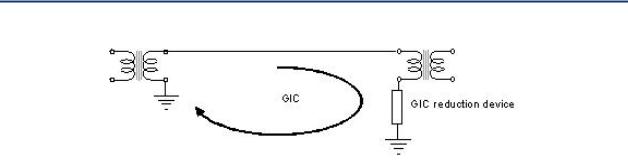
In principle, the simplest approach to reduce GIC flows in substation equipment is to place relatively high impedance device in series with the path formed by the transmission circuit, the transformer, and Earth return (see Figure 39). The most economical and convenient point to place this impedance is in series with the neutral to ground connection of a transformer. The commonly proposed methods include either a neutral resistor or a capacitor.
However, line configuration and equipment can also alter GIC flows. For example, series compensated lines automatically reduce or block GIC, although GIC blocking is not the driver for the installation of series compensation capacitors. Hydro Québec has implemented series compensation on its main grid, mainly for stability reasons, and Hydro Québec has also used specific capacitors blocking devices on three AC transmission lines close to Radisson substation, for the express purpose of blocking DC current coming from GIC or from a nearby DC tie. The application of line series capacitor banks is a mature technology, which can be costly, but has a significant operating history. Series capacitors are covered by IEEE Standard 824.114
The term “GIC blocker” is sometimes used to describe a GIC reduction device or GIC Mitigation System. (This is probably misleading in the case of a neutral resistor since their values are typically in the 2 to 5 range and the level of reduction achieved depends on the relative resistance of the transformer line resistor loop.) A neutral capacitor inserts larger impedance into the loop at GIC frequencies of 1 milliHertz to 100 milliHertz, and its effect would be relatively independent of the resistances in the loop. Nevertheless, the term GIC Reduction Device (GRD) is more precise and is used throughout this chapter.
113The testing consisted of computer simulations, laboratory prototypes, and in actual full scale projects installed at Minnesota Power. These EPRI projects, documented in reports EL 3295 (December 1983) and TR 100450 (June 1992), demonstrated the viability of neutral blocking devices for mitigating the effects of GIC.
114IEEE Standard 824 2004 is focused on series capacitor bank components and bank duty cycle ratings, equipment insulation levels, protective functions, component testing, instruction books, nameplates, and safety. This is the current version of the standard and represents a significant update to its predecessor, IEEE 824 1994.
Effects of Geomagnetic Disturbances on the Bulk Power System–February 2012 |
73 |
Chapter 10–GIC Reduction Devices
Figure 39: Placement of a GIC reduction device (GRD)
The largest GIC flows in an HV network normally take place at voltage levels above 230 kV. Transmission circuits below 230 kV generally have much higher DC resistance per unit length, and their contribution can be ignored in most cases. Similarly, the higher the operating voltage, the lower the resistance per unit length of the transmission circuit is and the higher the GIC flow for a given induced geoelectric field. For instance, the DC resistance of a 230 kV line can range from 0.04 to 0.06 / km, while the resistance of 500 kV lines can range from 0.01 to 0.02/km.
The GIC injected by a transmission circuit become constant, regardless of line length, when the resistance of the line dominates the resistance of the loop (because both line resistance and induced geoelectric field are proportional to line length). For instance, GIC in a double circuit becomes practically constant after 50 km, whereas a double circuit 500 kV line becomes practically constant after 100 km.
Winding resistances of transformers depend on the MVA rating and winding voltage levels. For transformers in the 230 kV to 500 kV class, winding resistances can range from 0.05 to 0.5 . In Figure 37, the loop resistance of the circuit is 1.15 , and it consists of the line resistance (assuming a 100 km, 500 kV line; RDC = 0.01 /km), a transformer winding resistance of 0.05, and a station grounding resistance of 0.1 .
A 2 neutral resistor in the single phase loop shown in Figure 39 would reduce GIC by a factor of 1.15/3.15 = 0.37. In a three phase network, the reduction of GIC per phase with a 2 neutral resistor is found below in Equation 3.
Equation 3: Calculation of GIC per phase
1 0.05 3 0.1 |
|
0.18 |
|
1 0.05 3 (0.1 |
2) |
||
|
10.2 Placement of a GIC Reduction Device
The effects of a single GIC reduction device are local in nature because only GIC flowing in one loop is reduced. In the system shown in Figure 40, a GIC reduction device placed in only one transformer would shift the total GIC contributed by the lines connecting to station to the other transformer.
74 |
GMDTF Interim Report: Affects of Geomagnetic Disturbances on the Bulk Power System–February 2012 |
Chapter 10–GIC Reduction Devices
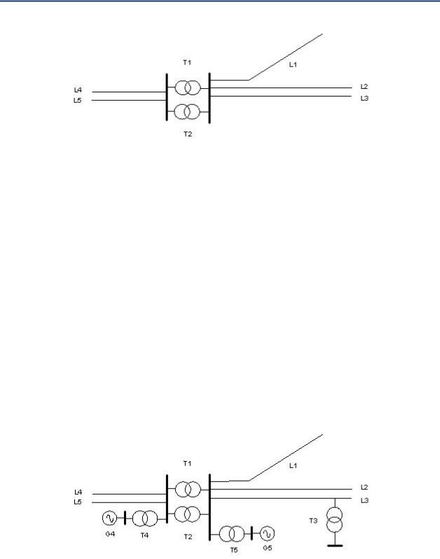
Figure 40: Simple HV network
The placement of a GIC reduction device depends on where the reduction in GIC is required or identified by system study. When the area or location of GIC reduction is identified, there are a number of system and equipment factors to consider, such as:
Transformer winding connection (e.g., wye delta, or wye wye – tertiary windings are normally ignored in quasi DC GIC calculations).
Type of transformer (e.g., two winding or autotransformer).
Type of network connection (e.g., line tap, transmission station).
Type of network configuration (radial or meshed).
Orientation of the circuits that form part of or are connected to the loop.
In addition, a system study needs to be carried out to assess the effect of the GIC reduction device on multiple system configurations and conditions. Further interconnection wide study is required to determine how GIC reduction devices s may redistribute the flow of GIC across the system, influencing GIC in other transformers and on the network of neighboring interconnected systems.
Figure 41: HV transmission network with generator step up (T4 &T5) and local supply transformer (T3)
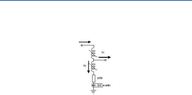
From the point of view of GIC, a DC current reduction device connected to the neutral of an autotransformer can reduce the amount of GIC in the common winding, which in turn reduces the level of saturation of the selected transformer, and reduces impacts on harmonic generation and effective reactive power loss. However, the neutral impedance will also have the effect of allowing more “through” current to circulate in the HV and low voltage (LV)
Effects of Geomagnetic Disturbances on the Bulk Power System–February 2012 |
75 |
Chapter 10–GIC Reduction Devices
terminals (see Figure 42). In a more complex situation, like the one shown in Figure 41, placing GIC reduction device at autotransformers located at points T1 and T2 would likely push/transfer GIC into step up transformers located at points T4 and T5.
Figure 42: GIC flow in an autotransformer
Placement of a GIC reduction device on a tap transformer (e.g., T3 in Figure 41) only reduces the GIC flow on that transformer.
The orientation of the transmission lines connected to the transformer buses can have a significant influence on the placement of GIC reduction devices. Typically in planning studies, GIC flow is calculated twice: first assuming east west (E W) electric field orientation and then assuming a north south (N S) field orientation. If the geoelectric field can be assumed to be uniform or coincident in the system under consideration, the worst case potential maximum will be the vector sum of GIC N S orientation and GIC E W orientation.
10.3 Selection of GIC Reduction Devices
The evaluation of the advantages and disadvantages of vendor specific GIC reduction devices is not within the scope of this report. However, installing impedances in the neutral of a transformer can pose electrical considerations that can affect transformer reliability and safety. Typical transformer insulation systems are originally designed as solidly grounded wye systems. These designs typically incorporate a reduced transformer neutral basic insulation level (BIL) rating. Inserting impedance in the neutral connection can create voltage levels that exceed the transformer neutral BIL rating. Therefore, engineers must account for and limit overvoltages at the neutral and phases for the full range of operating conditions: including, but not limited to through faults, load imbalances, transient recovery voltage (TRV) events, excessive third harmonics, lightning, internal faults, bolted faults, circulating currents, ferroresonance, etc.
The general functional requirements and system issues that should be taken into consideration in the specification of a GIC reduction device will be discussed. These depend on whether a resistor or a capacitor is used as the GIC reduction device.
10.3.1 Neutral Resistors
The specification of the size of a neutral resistor depends on a number of factors:
Maximum overvoltage across the resistor during fault and transient conditions. The neutral of a transformer designed to be solidly or impedance grounded may have a
76 |
GMDTF Interim Report: Affects of Geomagnetic Disturbances on the Bulk Power System–February 2012 |

Chapter 10–GIC Reduction Devices
relatively low neutral BIL. The size of the resistor is constrained by neutral currents during ground faults. Overvoltage due to switching transients can be managed with a neutral surge arrester.
Transient overvoltage (TOV) during ground faults should be reviewed against existing surge arrester TOV ratings.
Effect on protection systems. The size of the resistor must be low compared to the winding impedances to keep the transformer effectively grounded. Care in selecting resistor size must be taken not to desensitize relay settings.
Transient and continuous thermal ratings. These are determined by ground fault currents and system imbalance assumptions, respectively.
Physical size. For example, one vendor estimates the dimensions of a 2 resistor rated for 12 kA fault currents as approximately 17 feet in length, 8 feet in height, and 6 feet in width.
Insertion or bypass. A neutral resistor can be left permanently connected to the neutral of a transformer if the system imbalance and continuous rating of the resistor are such that thermal losses are not an issue. Otherwise, a bypass breaker or load break switch is needed to insert the resistor during a GMD event, and remove it when it is not needed.
Failure mode. The resistor assembly must be instrumented and bypassed upon failure of any component (e.g., resistor or arrester failure).
10.3.2 Neutral Capacitors
A neutral capacitor represents the introduction of large impedance into a GIC loop at GIC frequencies. Therefore, potential GIC reduction in a given loop is much higher than with a neutral resistor. However, the ohmic value at 60 Hz has to be very low to reduce the impact on the power system, which indicates a large capacitance. The specification of a neutral capacitor depends on a number of factors:
Ohmic value should be low. 43.2 have been suggested in the literature. This means a physically large capacitor.115
Short circuit and steady state rating. A neutral capacitor may increase ground fault levels. In such a case, it must be managed with a reliable bypass scheme. It may not be an option in stations at or close to their short circuit limits.
Since the capacitance is large, there is the risk of creating linear harmonic resonance. Further, to avoid displacing GIC to other transformers in the station, multiple neutral capacitors would have to be installed, thus potentially increasing the risk of linear resonance at even lower frequencies. Linear resonance can create extremely high overvoltage and catastrophic insulation failure. The need to avoid linear resonance is not preempted by the use of a bypass scheme, since the loss or failure of a bypass scheme is a valid contingency. Therefore, a careful
115 Kappenman, J.G.; Norr, S.R.; Sweezy, G.A.; Carlson, D.L.; Albertson, V.D.; Harder, J.E.; Damsky, B.L.; , "GIC mitigation: a neutral blocking/bypass device to prevent the flow of GIC in power systems," Power Delivery, IEEE Transactions on , vol.6, no.3, pp.1271 1281, July 1991
Effects of Geomagnetic Disturbances on the Bulk Power System–February 2012 |
77 |

Chapter 10–GIC Reduction Devices
harmonic resonance assessment taking into consideration maintenance outages and other possible configuration changes is necessary.
Maximum overvoltage across the capacitor during steady state and ground fault condition may be managed with a bypass scheme.
Bypass scheme: This issue is more complex in the case of neutral capacitors than in the case of neutral resistors. In the case of a fault or other system transients, it requires a fast bypass element (usually with a choke and a damping resistor), as well as a slower bypass breaker. Additionally, control circuitry/logic is needed to provide the firing signal to the bypass device, possibly based either on neutral current or neutral voltage supervision. From a power engineer’s point of view, this would be similar to the specification of a series compensation capacitor assembly, but at a smaller scale.
Failure mode: Given the complexity of the assembly, component failure is expected to require taking the transformer out of service.
The use of GIC reduction devices require system studies that may grow in complexity with the number of devices installed. The effect of GIC reduction devices is relatively local and according to Kirchoff’s Law, there is no way to avoid GIC flow redistribution. The implementation of GIC reduction device must be considered in the backdrop of cost, the criticality of the equipment that is meant to be protected, the vulnerability of the transformer, the impact of flow diversion to other transformers, and the inevitable loss of reliability caused by the introduction of complex non static equipment into the power system.
10.4 Functional Specification of GIC Reduction Devices
A functional specification defines in high level terms the expected performance of a device. Functional specifications depend on a number of factors, such as the ones discussed in Section 11.3. On the other hand, a functional specification must meet specific utility, operator, and regulatory requirements. The following is presented as an illustrative example.
Fail safe – the assembly must provide a ground path at all times.
The assembly must not create any linear or ferroresonance conditions – under normal operation or due to the failure of one its components.
The assembly must be maintainable – removed and re inserted without transformer outage.
The system must:
o Handle insertion/bypass under GIC conditions
o Be able to withstand full range of normal and abnormal operating conditions o Be controllable remotely with automatic sensing and insertion
o Incorporate self diagnostics
o Meet applicable standards. If no standards exist, system components must meet applicable standards.
78 |
GMDTF Interim Report: Affects of Geomagnetic Disturbances on the Bulk Power System–February 2012 |