

Geomagnetic_Disturbance_Task_Force_2012
.pdfAttachment 7–A View on Risk Management
Attachment 7: A View on Risk Management
A7.1 Introduction
This section provides a risk assessment framework that an organization can consider. It is provided here as an illustrative example, as there are a number of approaches used by industry to address risks to the bulk power system reliability. The framework is designed to serve as a reference for the users, owners and operators of the bulk power system who perform an internal risk review. The strategy and steps outlined are based on industry information available at the time of this report and should be adjusted as more data and information becomes available.
A7.1.1 Risk Management Strategy Addresses Common Concerns
Table A7 1 presents the risk control strategy that will be employed to establish the illustrative framework for industry as presented later in this section.
Table A7 1: Aligning solar GMD threat mitigation concerns to a risk control strategy
Concern
Complicated problem that has many components; too difficult to manage.
Limited operational experience and historical reference available to assess the risk.
The threat appears to be rare in occurrence and it will be expensive to mitigate the risk.
Impacts from solar events vary in terms of location and system.
This risk is unlike the other risks managed on a daily basis to ensure system reliability; New and costly regulatory requirements will result.
Risk Management Strategy
Identify the vulnerable components and determine a reasonable set of actions to take, align them into a logical sequence and methodically work across multiple complexities to achieve results in measurable phases.
Collect known data and develop models and other simulation techniques to calculate and represent operational impacts.
There is “low hanging” fruit in the form of vulnerability studies that can be employed to improve the posture of the system from impact and can be readily integrated into existing funded programs.
A “large scale” approach is necessary due to the integrated nature of the operational components, reviewing effects on an interconnection wide basis. More vulnerable components can be isolated in reference to role in the system and targeted for advanced management procedures.
Training and education programs on the nature of the threat will allow bulk power System Operators to more rapidly identify areas for improvement and take actions when necessary. Likewise, increasing system resilience to this threat can increase system response interoperability for other high impact, low frequency (HILF) risks such as a combined cyber/physical attack on the system. Few regulatory adjustments may be necessary if this risk is managed under existing bulk power reliability standards.
A7.2 Engineering GMD Resiliency into the Bulk Power System
A7.2.1 - Ensuring Reliability of the Bulk Power System
There are a number of formal entities that have a key role in ensuring reliability. The specific risk to the North American bulk power system from severe solar GMD requires international coordination between many formal entities. In the United States, the Federal Energy Regulatory
109 |
GMDTF Interim Report: Affects of Geomagnetic Disturbances on the Bulk Power System–February 2012 |

Attachment 7–A View on Risk Management
Commission (FERC), NERC, the Department of Homeland Security (DHS), the Department of Energy (DOE), the National Aeronautics and Space Administration (NASA), the Electric Power Research Institute (EPRI), and the National Oceanic and Atmospheric Agency (NOAA) are key stakeholders. In Canada, the organizations with a lead role include Natural Resources Canada (NRCan), the National Energy Board (NEB), Provincial Authorities, and NERC. These organizations are working closely with industry stakeholders to assess the risk and determine the vulnerability of the system to this threat.
A7.2.2 What is the Vulnerability?
The North American bulk power system was not specifically designed to withstand the effects of a severe solar storm. Since 1989 a record of significant effects to the modern bulk power system from a solar event was established. Since then, there have been a number of isolated solar storm events in varying latitudes and strengths. All of these events have resulted in localized, rather than wide spread, damage to system components.
A7.2.3 The Risk of Geomagnetically Induced Current (GIC) to Extra High Voltage (EHV) Transformers and the System
The sun’s activity is monitored, and the frequency and severity of the solar spots that produce the coronal mass ejections (CME) of concern are statistically predicted and aligned to cycles of solar activity. This is a scientific process that is highly dependent on specific satellite assets used to monitor the sun’s activities and perform “space weather predictions” that are accurate enough to allow earth based System Operators to make timely operational decisions. When discussing the risk to bulk power system operations from a solar geomagnetic disturbance, the fundamental risk question is: How will GIC resulting from the CME affect different types of bulk system transformers (EHV and generator step up), circuit breaker performance, and the protective systems that comprise the ability of the bulk power system to maintain the security and reliability of energy supply? This includes the impact to reactive power demand and the capability of system operators to maintain voltage support and economic load dispatch, as well as, the effect of increased system harmonics on equipment not designed to withstand levels outside established standards (e.g., capacitor banks). GIC has been known to occur on bulk power systems, but GIC impact to the system has not traditionally been identified as a specific risk to track and monitor outside those jurisdictions that have seen impact in the past. At this time there is no centralized reporting system for power companies to report incidents involving GIC impact.
A7.3 EHV Transformer Considerations
As discussed earlier, the vulnerability of the transformer is a key component to this risk and determining the specific vulnerability will require a rigorous analysis process that incorporates the complexity of the problem. The process by which to examine this risk is by using analytical methods such as modeling and simulation and equipment testing. These methods will support changing transformer design or operational performance expectations when the system is under duress from GIC. Emerging trends in transformer vulnerability characteristics are presented in Table 5 later in this section for assistance in determining organizational asset vulnerability.
GMDTF Interim Report: Affects of Geomagnetic Disturbances on the Bulk Power System–February 2012 |
110 |

Attachment 7–A View on Risk Management
Age
Transformers are typically reliable, rugged equipment designed to operate over decades. The design life of a transformer is typically 25 to 30 years, although, with proper maintenance, units can operate for up to 60 years. New transformers can withstand many unusual system conditions. Over time, transformers can accumulate effects of aging and wear which affects the insulation properties that would provide resilience to the unit from short circuit faults, system overvoltages or other abnormal stresses. There is also loss of transformer life caused by overheating.
Acquisition Lead Time
The manufacturing capability of transformers within North America is limited at the time of this report. Above 500kV, most transformers are procured from non North American sources and typically take one to three years to acquire. In addition, these high voltage transformers are customized which can hinder the application of a North American “spare” strategy. However, spare equipment can play a vital transitional role, as the built in resiliency of the bulk power system industry meets the restoration requirements based on the effects from a specific event.
Geology
Information about the conductivity structure of Earth can be obtained from magnetotelluric soundings, with interpretation aided by consideration of other geophysical and geological information. This information can be used to produce a layered model that represents Earth’s conductivity structure below the region of a specific power system. The one dimensional Earth models (i.e., only considering variation with depth) can be used to calculate the surface impedance of Earth, and show its variation across the North American continent.
Transportation
EHV transformers require special handling while in transit to minimize internal shock to the mechanical components, as well as very specific internal environmental conditions that must be managed. The internal environment of a transformer is affected by many conditions to include moisture, dissolved gas levels, and other factors. In addition, EHV transformers are very large and require customized shipping strategies for each unit as well as heavy equipment on site to enable installation. These logistical factors contribute to the difficulty in supplying a spare transformer from a centralized source during an emergency. If the spare transformers are unavailable or if delivery is impeded by a regional impact from loss of power or other factors such as lack of access to specialized rail cars or trucks, inability to access roads, rail lines, or bridges, or inability to acquire fuel during a regional power outage, the ability to rapidly replace failed units may not be possible within required timeframes. Installing the replacement oftentimes requires the removal of the existing unit. In some cases, there are portable transformers that can be used as a temporary solution.
Increased Voltage of the North American Bulk Power System
Over the past few decades, power transfer requirements have increased, requiring extra high voltage (EHV) transmission. The transmission capacity is inversely related to the transmission resistance; therefore, low resistance lines coupled with high resistance grounding increases GIC levels injected into transformers.
111 |
GMDTF Interim Report: Affects of Geomagnetic Disturbances on the Bulk Power System–February 2012 |

Attachment 7–A View on Risk Management
Role in the System
The bulk power system has two primary aspects: transmission and generation. Electricity generation capabilities include nuclear, fossil, hydro, solar, natural gas and other sources. EHV transformers and generation step up units (GSU’s) are required to be operational for bulk electricity to be transmitted and ultimately distributed to local utilities. If there is an isolated failure of a few transformer units, electricity can be redistributed across other lines, but if there are many failures, the impact to electricity generation is immediate. The premise of reliable power is that the “load” remains balanced and generation matches consumption. The transition period where generation balances to new load demands is critical and can affect system stability. The cessation of generation activities in certain facilities such as nuclear plants adds risk to stability and most generating plants require access to reliable electricity to operate properly.
A7.3.1 Vulnerable to Resilient
While the process to determine the vulnerability of EHV transformers is important to defining vulnerability from GMD, there are actions and steps the bulk power industry can take to mitigate the effects on system reliability from solar events. Like other naturally occurring events such as inclement weather, severe thunderstorms, hurricanes, earthquake, etc., GMD has affected bulk power operations in the past and requires specific attention.
A7.3.2 Current State of Operations
As NERC works to understand the vulnerability and consequence of the risk of solar GMD to bulk power system reliability, it is important to understand the current ability of industry to respond to warnings of increased solar activity.
A7.3.3 Creating a Framework: The Integrated Vision for the Future
In order to establish a program to address this complex threat, it is valuable to create a basic framework that will allow individual program elements to be identified and then demonstrate how they integrate in order to achieve the desired result of a bulk power system that is inherently resilient to the effects of the sun. This framework can then serve as a roadmap for the industry to refer to as internal programs are established and it also highlights programs that are vital to the success of achieving this goal.
There are two basic steps that will be employed to create the appropriate framework. The first step is to identify the primary components and sub topics in order to establish a boundary to the planning process, and the second step is to create a phased strategy where individual actions can be aligned into “actionable” processes conducted over a period of time.
GMDTF Interim Report: Affects of Geomagnetic Disturbances on the Bulk Power System–February 2012 |
112 |
Attachment 7–A View on Risk Management
A7.3.4 Step One: Identify the Components
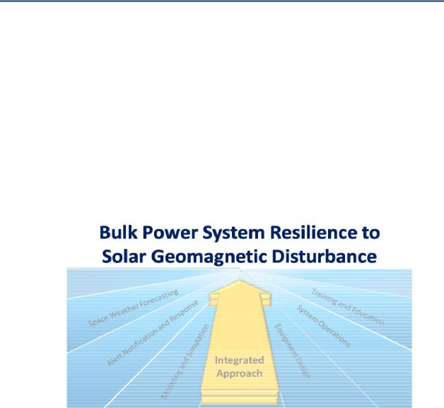
There are program categories in Figure A7 1 currently identified to capture the basic program elements under consideration at this time. These are as follows:
1.Space Weather Forecasting
2.Alert Notification and Response
3.System and Operational Planning: Modeling and Simulation
4.Equipment Design
5.System Operations
6.Training and Education
Figure A7 1: Integrated approach–bulk power system resilience to geomagnetic disturbances
Figure A7 2 provides an example of how to assign sub components (sub topics) within the larger program categories. This document provides specific information on many of these sub topics aligned to the program categories. Additionally, some sub topics may belong to more than one program categories.
113 |
GMDTF Interim Report: Affects of Geomagnetic Disturbances on the Bulk Power System–February 2012 |

Attachment 7–A View on Risk Management
Figure A7 2: Primary and sub components of understanding and mitigating risk
Space Weather Forecasting
•Scientific space based satellite assets and facilities to assess the potential impact to earth
•Interface across organizations
•Timing and expected impact duration
•Historical Data
Training and Education
•Awareness Programs
•Certification Programs
•Exercises
•Outreach Programs
System Operations
•Pre, During and Post event Operational Protocols
•Regulatory Requirements
•Emergency Management Procedures
•Communications
Equipment Design
• Design Standards
• EHV Transformers
• Test and Evaluation
• Acquisition Strategies
• Protective Components
Alert Notification and Response
•K Indices and other severity measurement scales
•Process to alert the industry
•Role of organization
•Timeframe for decision making
Modeling and Simulation
•Existing or postulated data
•GIC impact
•Equipment and System Vulnerabilities
A7.3.5 Step Two: Assess the Components Using a Phased Approach
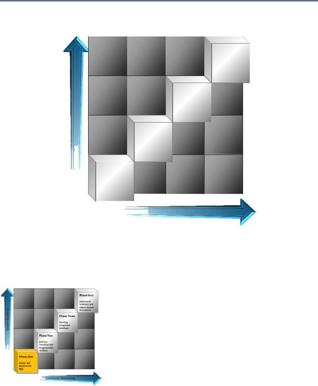
Once the program components and sub components are identified, there remains a requirement to address the sequencing of the expected actions associated with developing solutions to mitigate the risk. For this process, four primary phases of activity have been identified. These are shown in Figure A7 3.
GMDTF Interim Report: Affects of Geomagnetic Disturbances on the Bulk Power System–February 2012 |
114 |
Attachment 7–A View on Risk Management
Figure A7 3: Developing a phased approach
System Resiliency
Phase Four
Implement
Solutions and
Adjust System
Procedures
Phase Three
Develop
Integrated
Solutions
Phase Two
Perform
Technical and
Programmatic
Analysis
Phase One
Assess and
Baseline the
Risk
Continuous Monitoring
A7.4 A Four-Phased Strategy to Address the Threat
A7.4.1 Phase One: Assess and Baseline the Risk
The purpose of this phase is to assess existing data, identify the individual components of the threat, determine system limits, identify vulnerabilities and assess the scientific and engineering challenges to achieve desired resiliency.
Typically, when assessing risk to an organization from any threat, the traditional method has been to focus on planning for “catastrophic” level events. This provides a level of resilience when a negligible or moderate incident occurs. The “design basis threat” typically represents the credible threat that a system needs to be designed to withstand or be
inherently resilient. In the case of solar GMD and GIC, the use of formal analysis (pre and post event as well as simulated results) and additional data gathering is needed to refine how to improve bulk power system resilience to this threat.
115 |
GMDTF Interim Report: Affects of Geomagnetic Disturbances on the Bulk Power System–February 2012 |
Attachment 7–A View on Risk Management
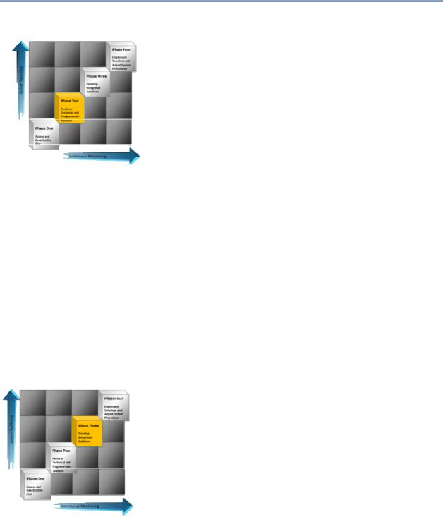
A7.4.2 Phase Two: Perform Technical and Programmatic Analysis
The next phase in this process involves performing an in depth scientific, mathematical and engineering analysis to further validate and predict system performance expectations against various scenarios. This phase involves the refinement or development of specific modeling and simulation capabilities, as well as physical testing of existing equipment to further understand the vulnerability and then develop solutions. These solutions include databases, software, models, reports, procedures, and other tangible results.
An important aspect of this phase is the ability to collect accurate data of system impacts as they continue to occur. For example, the sun will continue to impact Earth while this analysis is underway, so the ability to integrate changing data into this process is necessary. Formal data repositories and continued discussion across the North American and International bulk power industry will serve as an enabler during this process, as will the ability to openly share technical data and results. Once the risk is understood and an organizational baseline is created to define the potential vulnerability, the next step involves performing the technical and programmatic analysis required to further define and capture results that will allow for changes in system design and in operational procedures. This quantitative and qualitative analysis will allow leadership to make decisions concerning the need to make significant changes in the bulk power system to increase resiliency to this threat. In addition to the technical analysis performed, there are programmatic reviews that an organization can perform to assess the threat.
A7.4.3 Phase Three: Develop Integrated Solutions
Once the analysis and awareness activities conducted during Phase Two are developed, the next step is to integrate the results and develop solutions. Phase Three represents the point where the system begins to achieve an increased state of resilience; the threat has been defined, the system has been analyzed, quantitative and qualitative results are being produced, and the organization understands the threat. These individual solutions and successes can then be integrated formally to change the dynamic of the risk. At first, the system becomes more resilient as operational procedures are adjusted based on the analysis, but then as acquisition strategies and
vulnerable asset replacement programs, or other proposed solutions are implemented, the system becomes more resilient because it has being “engineered” to operate during solar events.
An important aspect to this phase is the review and creation of standards, regulatory requirements, system operator certifications, and acquisition policies. In certain cases, the results and recommendations can be accommodated within existing policies, but if changes are required, these would be produced in this phase, or validated and ready for implementation.
GMDTF Interim Report: Affects of Geomagnetic Disturbances on the Bulk Power System–February 2012 |
116 |
Attachment 7–A View on Risk Management
The organization and industry has the data that will allow decisions to be made. Phase Three is when decisions about changes to the system are made, funded and inserted into formal programs and plans.
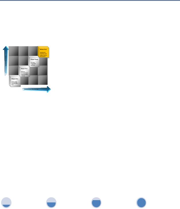
A7.4.4 Phase Four: Implement Solutions & Adjust System Procedures
Phase Four represents the point when the system is now becoming “designed” to operate in a resilient manner in the face of the threat. The risk is understood, technical and programmatic analysis has been performed, and the solutions have been identified and are either implemented or are in the process of being implemented. Solutions have been developed that can be incorporated into the operational environment and as a result, system procedures and other methods for ensuring optimal bulk power system performance will require a program to monitor the system on a continuous basis.
Each preceding Phase provided a foundation for Phase Four, but this is not an end state. Like other complicated threats, the behavior of the system when under duress will be affected by myriad internal and external factors and over time, the system will change dynamically in terms of operational concepts, new technologies, and standards for performance. Additionally, there will be lessons learned and increased awareness of how the bulk power system will respond when these naturally occurring events happen. The goal of completing the steps in each Phase is to achieve a level of resiliency to a known vulnerability but once that is achieved, the plans and concepts developed to achieve this state can’t be placed on a shelf. Rather, the objective is to seamlessly integrate the solutions into the day to day risk management posture of the system.
A7.5 Steps to Take In Each Phase
Figure A7 4 provides an overview of the steps an organization could take in each Phase. These steps can be used when performing a self assessment of bulk power systems.
Figure A7 4: Steps to take in each phase
Phase One: Assess and Baseline the Risk
Integrate Into Existing Organizational Risk Programs
Collect and Analyze Historical Data Concerning the Threat of Impact for Planning Purposes
Identify Vulnerable Assets
Phase Two: Perform |
|
Phase Four: Implement |
Technical and |
Phase Three: Develop |
Solutions and Adjust |
Programmatic Analysis |
Integrated Solutions |
System Procedures |
Select A Group of |
Incorporate Results Into |
Review Results and Update |
Vulnerable Assets to Focus |
Operational and |
Plans and Procedures |
on for Technical Analysis |
Programmatic Processes |
|
Identify Organizational |
|
|
Resources to Support |
|
|
Further Analysis |
|
|
Prepare to Collaborate With |
|
|
Industry wide Initiatives |
|
|
Initiate GIC Risk Awareness |
|
|
Programs Across the |
|
|
Organization |
|
|
117 |
GMDTF Interim Report: Affects of Geomagnetic Disturbances on the Bulk Power System–February 2012 |

Attachment 8–Example of GIC Calculation
Attachment 8: Example of GIC Calculations
A8.1 Introduction
This attachment presents the method to calculate the distribution of GIC in a power network based on the considerations described in Chapter 8. Numerical examples are also provided as an engineering reference.
A8.2 Calculation of GIC in HV and EHV Networks
During geomagnetic disturbances, magnetic field variations drive electric currents along transmission lines and through transformer windings to ground. These geomagnetically induced currents (GICs) produce half cycle saturation in transformers, leading to harmonic generation and increased reactive power demand. As part of assessing the hazard to power systems and planning mitigation, it is necessary to model GIC produced to different levels of geomagnetic activity. The following sections provide an overview of the modeling procedure for determining GIC in high voltage (HV) and extra high voltage (EHV) networks.
A number of complex phenomena cause Earth’s magnetic field to vary slowly with time. Changes in Earth’s magnetic field density with respect to time (i.e., dB/dt) are generally on the order of millihertz (mHz). These changes in Earth’s magnetic field produce an electric field at Earth’s surface, resulting in an induced voltage along the length of the transmission line via Faraday’s Law. The resulting induced voltage drives GIC flow in the system wherever a path for current flow exists. Connections to ground are not a prerequisite for GIC flow [1] to occur. This process is illustrated for the simple two bus system shown in Figure A8 1.
GMDTF Interim Report: Affects of Geomagnetic Disturbances on the Bulk Power System–February 2012 |
118 |