

CCNP 642-811 BCMSN Exam Certification Guide - Cisco press
.pdf386 Chapter 16: Quality of Service Overview
Table 16-2 Mapping of IP Precedence and DSCP Fields (Continued)
IP Precedence (3 bits) |
|
DSCP (6 bits) |
|
|
|
|
||
|
|
|
|
|
|
|
|
|
|
|
|
Per-Hop |
Class |
Drop |
Codepoint |
DSCP Bits |
|
Name |
Value |
Bits |
Behavior |
Selector |
Precedence |
Name |
(decimal) |
|
|
|
|
|
|
|
|
|
|
Flash |
4 |
100 |
AF |
4 |
1: Low |
AF41 |
100 010 |
(34) |
Override |
|
|
|
|
|
|
|
|
|
|
|
|
2: Medium |
AF42 |
100 100 |
(36) |
|
|
|
|
|
|
||||
|
|
|
|
|
|
|
|
|
|
|
|
|
|
3: High |
AF43 |
100 110 |
(38) |
|
|
|
|
|
|
|
|
|
Critical1 |
5 |
101 |
EF |
|
|
EF |
101 110 |
(46)1 |
Internetwork |
6 |
110 |
— |
|
|
|
(48-55) |
|
Control |
|
|
|
|
|
|
|
|
|
|
|
|
|
|
|
|
|
Network |
7 |
111 |
— |
|
|
|
(56-63) |
|
Control |
|
|
|
|
|
|
|
|
|
|
|
|
|
|
|
|
|
1IP Precedence value 5 (DSCP EF) corresponds to the range of DSCP bits 101000 through 101111, or 40-47. However, only the value 101110 or 46 is commonly used and is given the EF designation.
Class Selector
The three class selector bits (DS5 through DS3) coarsely classify packets into one of seven classes:
■Class 0, the default class, offers only best-effort forwarding.
■Classes 1 through 4 are called Assured Forwarding (AF) service levels. Higher AF class numbers indicate the presence of higher-priority traffic.
Packets in the AF classes can be dropped, if necessary, with the lower-class numbers the most likely to be dropped. For example, packets with AF Class 4 will be delivered in preference to packets with AF Class 3.
■Class 5 is known as Expedited Forwarding (EF), where those packets are given premium service. EF is the least likely to be dropped, so it is always reserved for time-critical data such as voice traffic.
■Classes 6 and 7 are called Internetwork Control and Network Control, respectively, and are set aside for network control traffic. Usually, routers and switches use these classes for things like Spanning Tree Protocol and routing protocols. This ensures timely delivery of the packets that keep the network stable and operational.
Drop Precedence
Each class represented in the DSCP also has three levels of drop precedence, contained in bits DS2 through DS0 (DS0 is always zero):
QoS Building Blocks 387
■Low (1)
■Medium (2)
■High (3)
Within a class, packets marked with a higher drop precedence have the potential for being dropped before those with a lower value. In other words, a lower drop precedence value gives better service. This gives finer granularity to the decision of what packets to drop when necessary.
NOTE The DSCP value can be given as a codepoint name, with the class selector providing the two letters and a number followed by the drop precedence number. For example, class AF Level 2 with drop precedence 1 (low) is written as AF21. The DSCP is commonly given as a decimal value. For AF21, the decimal value is 18. The relationship is confusing, and Table 16-2 should be a handy aid.
You should try to remember a few codepoint names and numbers. Some common values are EF (46) and most of the classes with high drop precedences: AF41 (34), AF31 (26), AF21 (18), and AF11 (10). Naturally, the default DSCP has no name (0).
QoS Building Blocks
As a packet passes through a switch, many things can be examined or manipulated to alter its delivery in relation to other packets. QoS can then be thought of as a series of building blocks, where each represents a different operation on a packet.
Beyond that, the QoS building blocks can be identified in various internal locations within a Catalyst switch. To keep the QoS operations straight, always think of a packet traveling from the ingress port (where it arrives on a switch), through various internal queues and decisions, and to the egress port (where it exits the switch).
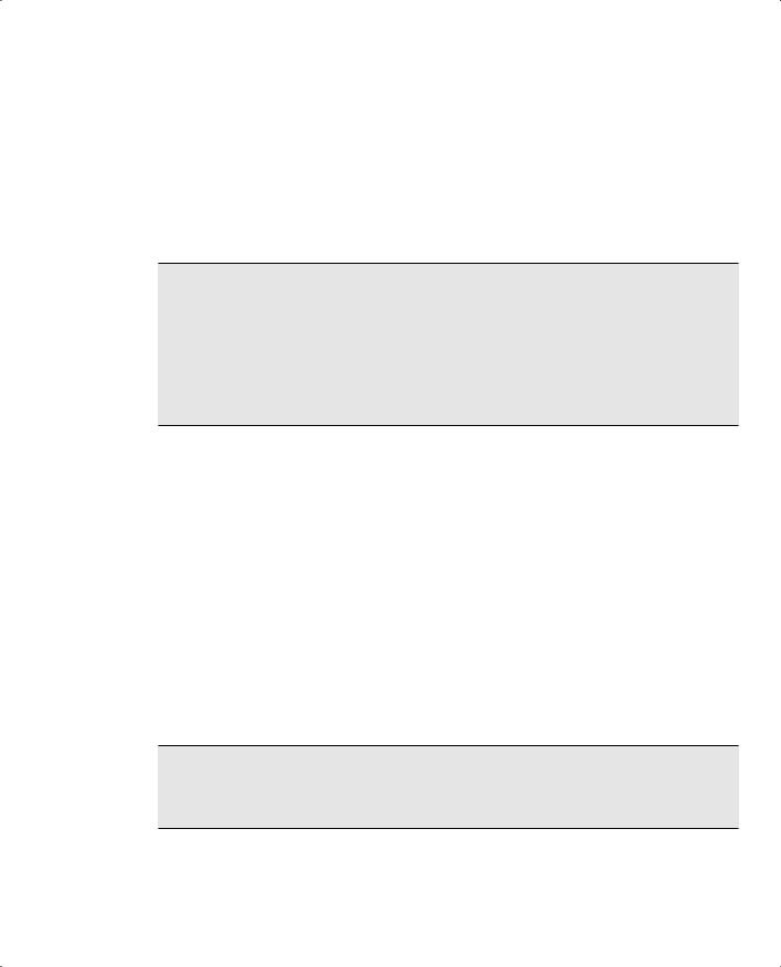
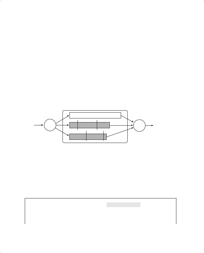
The QoS building blocks are discussed in the sections that follow. Refer to Figure 16-2 to see the packet flow path through a Catalyst switch, and where each QoS operation is performed. The path across the bottom of the figure shows how QoS parameters can be manipulated at each building block.
NOTE QoS within a Catalyst switch is based on the idea that each packet receives and carries an internal DSCP value with it while it moves through the switch. The internal DSCP is assigned according to how inbound QoS information is trusted, and can be manipulated or marked as a packet is forwarded.
388 Chapter 16: Quality of Service Overview
Figure 16-2 Catalyst Switch QoS Operations and Internal DSCP
|
|
Catalyst Switch |
|
|
|
||
Ingress Port |
Classification |
|
Marking |
Scheduling |
Congestion |
|
|
or |
and |
Policers |
Egress |
||||
Avoidance |
|||||||
VLAN |
Trust |
|
|
|
Port |
||
|
|
|
|
||||
CoS |
|
|
|
Choose Queue |
Choose |
|
|
|
|
CoS |
Queue 1 |
Drop Thresholds |
|
||
|
|
Markdown |
|
||||
DSCP |
|
|
|
||||
|
Map |
DSCP |
Queue 2 |
Queue |
Transmit |
||
IP Prec |
Compute |
Drop |
... |
Frame |
|||
IP Prec |
Priority |
|
|||||
Internal |
% |
|
|||||
Port Default CoS |
|
|
|||||
DSCP |
|
|
|
|
|
||
Operations on QoS Values
Ingress Queueing
As packets are received on a switch port, they are placed in an ingress queue. In the most basic form, packets are copied into an ingress queue in the order they are received. This queue gives some buffer space so that packets can be stored up during the time the switch is busy forwarding the previous packet.
Catalyst switches offer multiple ingress queues so that packets can be serviced differently—even as they arrive at a switch port. Most switches have two types of ingress queues: a strict priority queue and a standard queue. If QoS is enabled at all, some packets are automatically placed in the strict priority queue so that they can be serviced ahead of packets in the standard queue. Typically, packets that arrive on a trunk with a CoS value of 5 (usually the highest priority, used for voice traffic) are placed into the strict priority queue.
You can also tune the ingress queues according to their size ratio, how packets are scheduled for servicing, and so on.
TIP The BCMSN course and this text do not cover ingress queueing strategies or configuration. This is because the most common QoS operations involve packet manipulation after the packet has been received. Be acquainted only with the fact that ingress queueing is always occurring in a Catalyst switch, and that it can be tuned.
Classification, Trust, and Marking
To manipulate packets according to QoS policies, a switch must somehow identify which level of service each packet should receive. This process is known as classification, where each packet is classified according to the type of traffic (UDP or TCP port number, for example), according to parameters matched by an access list, or something more complex, such as by stateful inspection of a traffic flow.

QoS Building Blocks 389
Recall that IP packets carry a ToS or DSCP value within their headers as they travel around a network. Frames on a trunk can also have CoS values associated with them. A switch can then decide whether to trust the ToS, DSCP, or CoS values already assigned to inbound packets. If it trusts any of these values, the values are carried over and used to make QoS decisions inside the switch.
If the QoS values are not trusted, they can be reassigned or overruled. This way, a switch can set the values to something known and trusted, and something that falls within the QoS policies that must be met. This prevents nonpriority users in the network from falsely setting the ToS or DSCP values of their packets to inflated levels so that they receive priority service.
Every switch must decide whether to trust incoming QoS values. Generally, an organization should be able to trust QoS parameters anywhere inside its own network. At the boundary with another organization or service provider, QoS should typically not be trusted. It is also prudent to trust only QoS values that have been assigned by the network devices themselves. Therefore, the QoS values produced by the end users should not be trusted until the network can verify or override them.
The perimeter formed by switches that do not trust incoming QoS is called the trust boundary. Usually, the trust boundary exists at the furthest reaches of the enterprise network (access layer switches and WAN or ISP demarcation points). After the trust boundary has been identified and the switches there are configured with untrusted ports, everything else inside the perimeter can be configured to blindly trust incoming QoS values.
Finally, you can configure switches to mark or alter the QoS values of packets when needed. For example, at a trust boundary, a switch can override all inbound packets to have a certain known and trusted DSCP value. Elsewhere, traffic belonging to a certain application (IP protocol, UDP or TCP port) can be marked with a specific DSCP value to differentiate it from other types of traffic.
Policers
After packets have been classified, you can configure a switch to limit the bandwidth that certain types of traffic can use. For example, peer-to-peer file sharing might be less desirable than the flow of data for a patient’s MRI scans. The peer-to-peer traffic could be classified and then rate-limited to below a specific bandwidth.
Rate limiting is performed by traffic policers, which can determine if a classified type of traffic is being forwarded too often. If so, either those packets can be dropped to fall within the required bandwidth, or their DSCP values can be lowered to receive a lesser level of service.
390 Chapter 16: Quality of Service Overview
Policers come in two varieties:
■Microflow policers—Keep track of the bandwidth used by very granular traffic flows, such as between a source and destination address, using specific source and destination port numbers.
■Aggregate policers—Monitor and control a cumulative flow that travels through one or more ingress ports or VLANs.
Traffic flows that fall within the policer limits are called conforming or in-profile. Flows that exceed the bandwidth limits are called exceeding, violating, or out-of-profile.
TIP The BCMSN course and this text do not cover policers or their configuration. Be acquainted only with the basic knowledge that policers (both microflow and aggregate) are available in the QoS toolkit on Catalyst switches.
Scheduling
Packets that are ready for forwarding or delivery are placed into egress queues. The queues are then serviced according to a predefined configurable scheduling method. Scheduling is also called egress queueing or congestion management because it tends to deal with network congestion on an egress port after the congestion occurs.
Catalyst switches usually have multiple queues available to each egress switch port. One queue is reserved as a strict priority queue and is always serviced ahead of any other queue. The strict priority queue buffers time-critical packets, such as the voice stream in a voice over IP (VoIP)
telephone call. The other egress queues are called standard queues and are serviced in a configurable priority—always below that of the strict priority queue.
Packets are assigned to the egress queues according to a mapping function, based on the CoS value. By default, packets with CoS 0 through 3 are assigned to the first standard queue, while CoS 4 through 7 go in the second standard queue.
Basically, congestion is managed in the way the queues are serviced. Catalyst switches use a technique called Weighted Round Robin (WRR). The size of each queue is configured as a percentage of the total queue space. Then, each queue is given a weight so that one with a higher weight is serviced before a queue with a lower weight. Queues are serviced in a round-robin fashion, one after another. The only exception is the priority queue, which always gets serviced until it is empty.

QoS Building Blocks 391
Congestion Avoidance
Switch port queues function to provide space for packets waiting to be transmitted when the port cannot transmit them immediately. If a port becomes congested, the queue begins to fill. What happens when the congestion is severe enough that the queue fills to capacity? New packets to be forwarded cannot be stored in the queue and must be dropped.
Somehow, a switch must anticipate or avoid severe congestion in advance using one of the following available methods:
■Tail drop
■Weighted Random Early Detection
Tail Drop
Tail drop is used as a most basic and drastic means to avoid congestion in port queues. Packets are placed in a queue where the “head” end is closest to being transmitted, and the “tail” end is farthest back in the queue. After the queue fills to capacity, any new packets arriving at the queue are simply dropped at the tail end of the queue.
While tail drop is easy to implement and requires little sophistication, it can have bad effects on existing traffic flows. With a TCP connection, when a packet is dropped, the sender perceives that there is congestion and begins to back off its retransmission timer. The transmission rate is reduced exponentially until the sender receives an acknowledgment indicating that the congestion has improved. Rather than beginning to send at a rapid rate again, the sender must go into the slow-start state, where packets are sent incrementally faster.
The overall effect of tail dropping is that all active TCP connections go into congestion back-off and then slow-start. All the TCP connections do this simultaneously, producing a condition called global synchronization. Bandwidth utilization on the switch port oscillates between 100 percent and a low value, rather than smoothly transitioning as the congestion goes away.
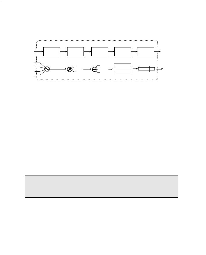
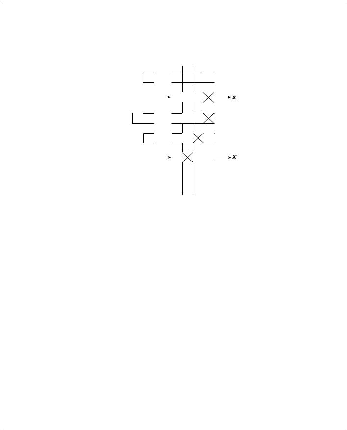
Figure 16-3 illustrates tail drop where a switch port queue is experiencing temporary congestion so that no packets can be transmitted. As packets enter the queue on the left, the queue begins to fill. When the queue is full, newly arriving packets are simply dropped. This is the case for Packet E.
392 Chapter 16: Quality of Service Overview
Figure 16-3 Example of Tail Drop in a Switch Port Queue
Packets |
|
|
|
|
Queues |
|
|
Congestion |
|||||
|
|
|
|
|
|
|
|
|
|
|
|
|
|
|
A |
|
|
|
|
|
|
|
|
|
A |
|
|
|
|
|
|
|
|
|
|
|
|
|
|
||
|
|
|
|
|
|
|
|
|
|
|
|
|
|
|
|
|
|
|
|
|
|
|
|
|
|
||
|
B |
|
|
|
|
|
|
|
|
B |
A |
|
|
|
|
|
|
|
|
|
|
|
|
|
|||
|
|
|
|
|
|
|
|
|
|
|
|
|
|
|
|
|
|
|
|
|
|
|
|
|
|||
|
C |
|
|
|
|
|
|
C |
|
B |
A |
|
|
|
|
|
|
|
|
|
|
|
|
||||
|
|
|
|
|
|
|
|
|
|
|
|
|
|
|
|
|
|
|
|
|
|
|
|
|
|||
|
D |
|
|
|
|
D |
|
C |
|
B |
A |
|
|
|
|
|
|
|
|
|
|
|
|||||
|
|
|
|
|
|
|
|
|
|
|
|
|
|
|
|
|
|
|
|
|
|
|
|
|
|||
|
E |
|
|
|
|
D |
|
C |
|
B |
A |
|
|
|
|
|
|
|
|
|
|
|
|||||
|
|
|
|
|
|
|
|
|
|
|
|
|
|
|
|
|
|
|
|
|
|
|
|
|
|
||
|
|
|
Drop |
|
|
|
|
|
|
|
|||
Weighted Random Early Detection
Weighted Random Early Detection (WRED) adds some intelligence to the tail drop congestion avoidance method. Rather than blindly dropping any packets that need to be added to a full queue, WRED attempts to randomly drop packets that are already in the queue so that the queue cannot become full.
Recall that each egress port has several assigned queues. Within each queue are several thresholds that WRED can use. Each threshold marks the queue level where WRED begins randomly dropping packets that have specific CoS values. For example, a queue might have threshold t1 at 50 percent for CoS values 0 and 1, and threshold t2 at 75 percent for CoS values 2 and 3. When the queue fills to 50 percent, WRED randomly drop packets with CoS 0 or 1 to reduce the queue size. If the queue fills to 75 percent, packets with CoS 2 or 3 randomly drop, but only after some CoS 0 or 1 packets are dropped first.
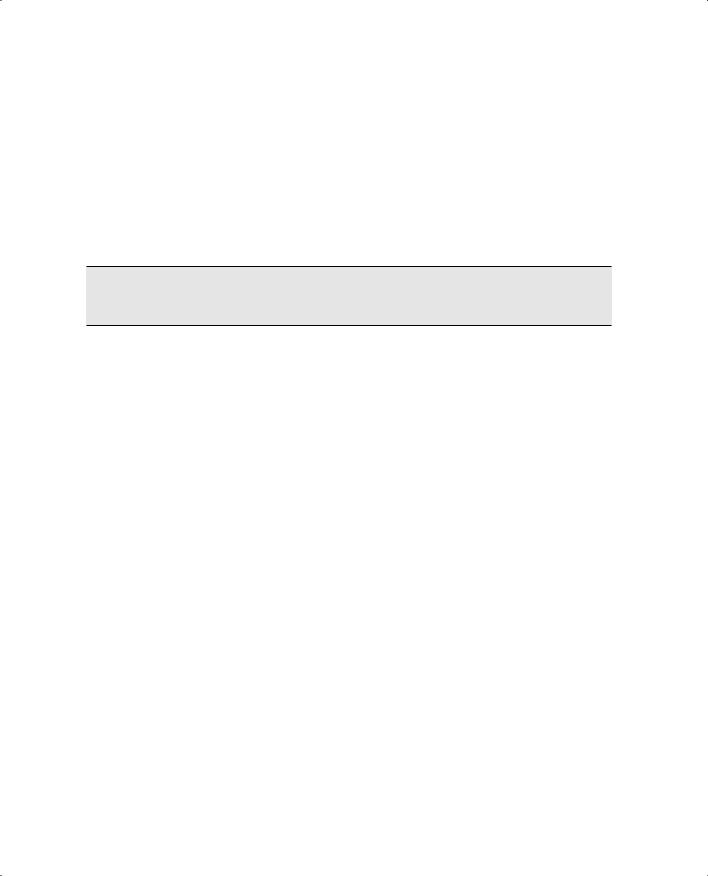
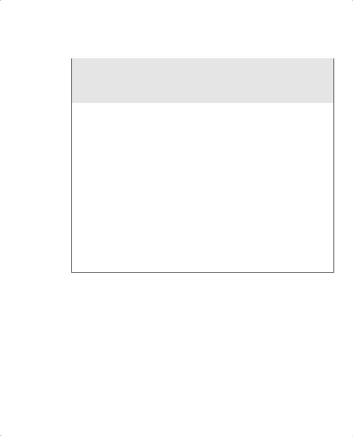
Figure 16-4 illustrates the WRED operation. A switch port queue has been configured with two WRED thresholds—t1 at 50 percent and t2 at 75 percent capacity. This port is undergoing congestion so that no packets can be transmitted. As packets arrive on the left, the queue begins to fill. For packets with CoS 0 or 1, WRED can randomly drop them from 0 percent up to the t1 threshold. This has happened to packet A (CoS 0). As packets D (CoS 2) and E (CoS 3) arrive, the same thing happens to packet B (CoS 0).
Switch Port Queues 393
Figure 16-4 Example of WRED in a Switch Port Queue
A0 = Packet CoS |
t2 t1 |
Congestion
A0 


 A0
A0 

B0 |
|
|
|
|
B0 |
A0 |
|
|
|
|
|
|
|||
|
|
|
|
|
|
Drop |
|
D 2  C3
C3 
 D2 C3 B0

Drop
E2 
 E2 D2 C3


|
|
|
|
|
Drop |
|
|
|
|
|
|
|
|
F 1 |
|
|
|
F 1 |
E2 |
C3 |
|
|
|
||||
|
|
|
|
Drop |
||
Packet D (CoS 2) has stayed below threshold t2. However, it too is subject to a random drop anywhere from 0 percent to t2. When packet E (CoS 2) and F (CoS 1) arrive, packet F is positioned above threshold t1. Above this threshold, any packets with CoS 0 or 1 are unconditionally dropped—so it goes with packet F.
WRED keeps the queue size manageable, while still giving preference to packets with higher CoS values. You can configure this behavior differently, however. Any queue threshold can be mapped to any CoS value.
Switch Port Queues
At this point in the chapter, you should know that each switch port has multiple queues assigned to it—both priority and standard queues. The queue sizes are configurable, as well as the QoS values of the packets that are placed in them. For congestion avoidance, each queue has multiple thresholds that trigger various packet drop actions.
It is important to also understand queue terminology and how Cisco labels and differentiates the queues. Each queue is configured or referenced by its queue ID. The lowest-priority standard queue is always Queue 1. The next-higher priority standard queues follow, beginning with Queue 2. The strict priority queue always receives the highest queue ID number.
394 Chapter 16: Quality of Service Overview
Each Catalyst switch port has a queue type notation associated with it. The type notation is of the form: xpyqzt, where each letter indicates the following:
■p—The number of strict priority queues, given by x
■q—The number of standard queues, given by y
■t—The number of configurable WRED thresholds per standard queue, given by z
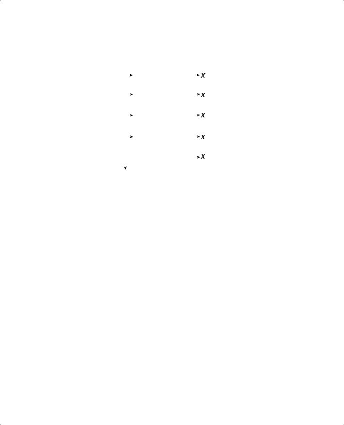
Therefore, a switch port of queue type 1p2q2t has one strict priority queue, two standard queues, and two WRED thresholds per standard queue. (The priority queue never has a threshold because no packets are ever proactively dropped.) Here, the low-priority standard queue is called Queue 1, the next-higher standard queue is called Queue 2, and the strict priority queue is called queue 3.
Figure 16-5 shows how this example’s port queues are arranged and identified.
Figure 16-5 Switch Port Queues and Their Type Notation
Switch Port
Egress Queues: 1p2q2t
|
3 |
|
p |
|
|
2 |
t2 |
t1 |
|
WRR |
q2 |
WRR |
||
|
||||
CoS-to-Queue |
|
t2 |
t1 |
|
1 |
q1 |
Scheduling |
||
Mapping |
|
|||
|
|
|||
|
|
|
||
|
|
|
WRED |
|
|
|
Congestion Avoidance |
||
On a Catalyst 6500, you can see what type of transmit or egress queues are available on a port with the show queueing interface type mod/num command. This command output also shows how the queues are arranged by queue ID order. On all IOS-based Catalyst switches, you can use the show interfaces type mod/num capabilities command to display similar information. Example 16-1 shows sample output from these two commands on two different switches.
Example 16-1 Determining the Transmit or Egress Queue Types Available on a Switch Port
Switch-Cat6500# show queueing interface gigabitethernet 1/1
Interface GigabitEthernet1/1 queueing strategy: Weighted Round-Robin
Port QoS is enabled
Port is untrusted
Extend trust state: not trusted [COS = 0]
Default COS is 0
Switch Port Queues 395
Example 16-1 Determining the Transmit or Egress Queue Types Available on a Switch Port
Transmit queues [type = 1p2q2t]:
Queue Id |
Scheduling Num of thresholds |
|||||
----------------------------------------- |
|
|
||||
1 |
WRR low |
2 |
|
|
|
|
2 |
WRR high |
2 |
|
|
|
|
3 |
Priority |
1 |
|
|
|
|
[more output deleted] |
|
|
|
|
|
|
|
|
|
|
|
||
Switch-3550# show interface gigabitethernet 0/1 capabilities |
||||||
GigabitEthernet0/1 |
|
|
|
|
|
|
Model: |
|
WS-C3550-48 |
||||
Type: |
|
unknown |
||||
Speed: |
|
1000 |
|
|
|
|
Duplex: |
|
full |
||||
Trunk encap. type: |
802.1Q,ISL |
|||||
Trunk mode: |
|
on,off,desirable,nonegotiate |
||||
Channel: |
|
yes |
||||
Broadcast suppression: |
percentage(0-100) |
|||||
Flowcontrol: |
|
rx-(off,on,desired),tx-(off,on,desired) |
||||
Fast Start: |
|
yes |
||||
QOS scheduling: |
rx-(1q0t), |
|
, |
|
|
|
tx-(4q2t) |
tx-(1p3q2t) |
|||||
CoS rewrite: |
|
yes |
|
|
|
|
ToS rewrite: |
|
yes |
||||
UDLD: |
|
yes |
||||
Inline power: |
|
no |
||||
SPAN: |
|
source/destination |
||||
PortSecure: |
|
yes |
||||
Dot1x: |
|
yes |
||||
Switch-3550# |
|
|
|
|
|
|
Notice in the shaded Catalyst 3550 output that two different queueing schemes are reported for the GigabitEthernet port. The port itself has four queues, each with two thresholds. When the expedite or strict priority egress queue is disabled, all four queues are standard queues (4q2t); when it is enabled, one queue becomes the strict priority queue, leaving three other standard queues (1p3q2t).