CCNP 642-811 BCMSN Exam Certification Guide - Cisco press
.pdf436 Chapter 18: IP Telephony
How Inline Power Works
A Catalyst switch with inline power always keeps the power disabled when a switch port is down. When a switch port first comes up, the switch sends out a 340-kHz test tone on the transmit pair of the twisted-pair Ethernet cable. A tone is transmitted rather than DC power because the switch must first detect an inline power-capable device before offering it power. Otherwise, other types of devices could be damaged.
An IP Phone loops the transmit and receive pairs of its Ethernet connection, even while it is powered off. When it is connected to an inline power switch port, the switch can “hear” its test tone looped back. Then it safely assumes that a powered device is present, and power can be applied to it. Inline power is provided over pairs 2 and 3 (RJ-45 pins 1,2 and 3,6) at 48V DC.
Note that the switch power supply must be sized appropriately to offer continuous power to an IP Phone on every powered switch port. Inline power is available on the Catalyst 3550-24-PWR, Catalyst 4500, and Catalyst 6500 platforms.
A switch first offers a default power allocation to the powered device. On a Catalyst 3550-24-PWR, for example, an IP Phone first receives 15.0 watts (0.36 amps at 48V DC). Now, the device has a chance to power up and bring its Ethernet link up, too. The switch then attempts a Cisco Discovery Protocol (CDP) message exchange with the device. This allows it to learn that the device is a Cisco IP Phone, as well as to learn the phone’s actual power requirements. The switch can then reduce the inline power to the amount requested by the phone.
To see this in operation, look at Example 18-1. Here, the power was reduced from 15,000 to 6300 milliwatts. This output was produced by the debug ilpower controller and debug cdp packets commands.
Example 18-1 Displaying Inline Power Adjustment
1d00h: ilpower_get_admin_state( Fa0/1 )
1d00h: ilpower_powerchange( Fa0/1 ) power: 15000 1d00h: ILP Power apply to ( Fa0/1 ) Okay
1d00h: ILP Power Accounting REQ_PWR ( Fa0/1 ) Okay 1d00h: ilpower_pd_statechange( Fa0/1 ) pd_class: 2
1d00h: ilpower_pd_power_statechange(Fa0/1) pd_power_state: 1
1d00h: %LINK-3-UPDOWN: Interface FastEthernet0/1, changed state to up
1d00h: %LINEPROTO-5-UPDOWN: Line protocol on Interface FastEthernet0/1, changed state to up
1d00h: CDP-PA: version 2 packet sent out on FastEthernet0/1
1d00h: CDP-PA: Packet received from SEP003094C35E4D on interface FastEthernet0/1 1d00h: **Entry NOT found in cache**
1d00h: ILP CDP request received ( Fa0/1 ), processing...
1d00h: ilpower_powerchange( Fa0/1 ) power: 6300
1d00h: ilpower_pd_name_change_via_cdp ( Fa0/1 ) pd name: Cisco IP Phone 7960
Voice VLANs 437
Configuring Inline Power
Inline power configuration is simple. Each switch port can automatically detect the presence of an inline power-capable device before applying power, or the feature can be disabled to ensure that the port can never detect or offer inline power. By default, every switch port attempts to discover an inline-powered device. To change this behavior, use the following interface configuration command:
Switch(config-if)# power inline {auto | never}
Voice VLANs
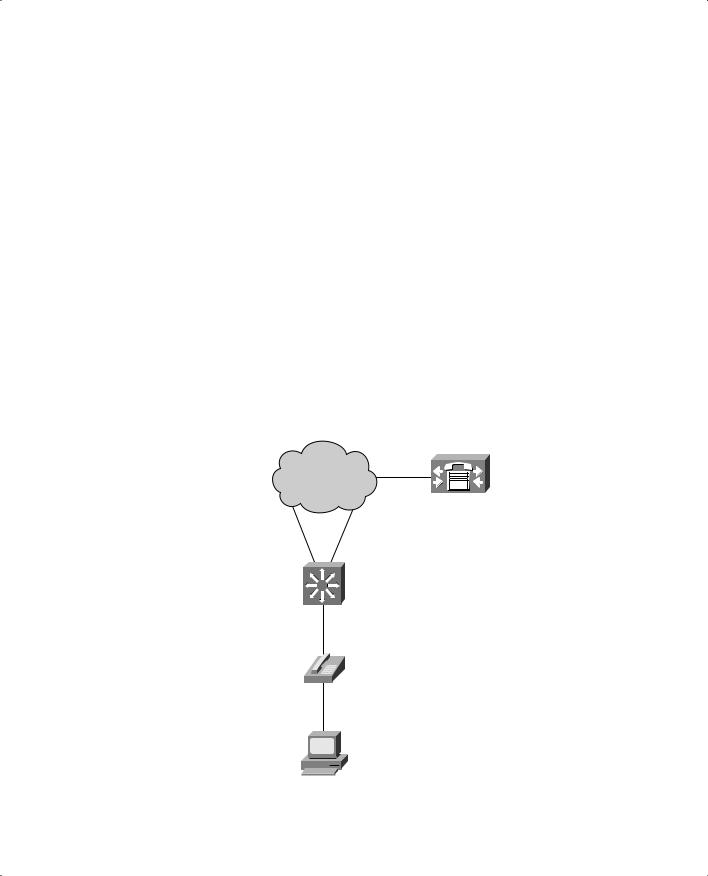
A Cisco IP Phone provides a data connection for a user’s PC, in addition to its own voice data stream. This allows a single Ethernet drop to be installed per user. The IP Phone can also control some aspects of how the packets (both voice and user data) are presented to the switch.
Most Cisco IP Phone models contain a three-port switch, connecting to the upstream switch, the user’s PC, and the internal VoIP datastream, as illustrated in Figure 18-1. The voice and user PC ports always function as access-mode switch ports. The port that connects to the upstream switch, however, can operate as an 802.1Q trunk or as an access-mode (single VLAN) port.
Figure 18-1 Basic Connections to a Cisco IP Phone
Distribution |
Cisco |
and |
CallManager |
Core Layers |
|
Access Layer
Catalyst
Power and Data 
Cisco
IP Phone
User PC

438 Chapter 18: IP Telephony
The link mode between the IP Phone and the switch is negotiated; you can configure the switch to instruct the phone to use a special-case 802.1Q trunk or a single VLAN access link. With a trunk, the voice traffic can be isolated from other user data, providing security and QoS capabilities. As an access link, both voice and data must be combined over the single VLAN. This simplifies other aspects of the switch configuration because a separate voice VLAN is not needed, but it could compromise the voice quality, depending on the PC application mix.
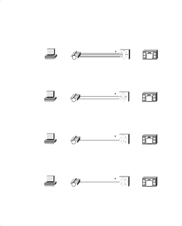
Voice VLAN Configuration
Although you can configure the IP Phone uplink as a trunk or nontrunk, the real consideration pertains to how the voice traffic will be encapsulated. The voice packets must be carried over a unique voice VLAN (known as the voice VLAN ID or VVID) or over the regular data VLAN (known as the native VLAN or the port VLAN ID, PVID). The QoS information from the voice packets must also be carried.
To configure the IP Phone uplink, just configure the switch port where it connects. The switch instructs the phone to follow the mode that is selected. In addition, the switch port does not need any special trunking configuration commands if a trunk is wanted. If an 802.1Q trunk is needed, a special-case trunk is negotiated by Dynamic Trunking Protocol (DTP) and CDP. Use the following interface configuration command to select the voice VLAN mode that will be used:
Switch(config-if)# switchport voice vlan {vlan-id | dot1p | untagged | none}
Figure 18-2 shows the four different voice VLAN configurations. Pay particular attention to the link between the IP Phone and the switch.
Table 18-2 documents the four different voice VLAN configurations.
Table 18-2 Trunking Modes with a Cisco IP Phone
|
Representation in |
Native VLAN |
|
Voice QoS |
Keyword |
Figure 18-2 |
(untagged) |
Voice VLAN |
(CoS bits) |
|
|
|
|
|
vlan-id |
A |
PC data |
VLAN vlan-id |
802.1p |
|
|
|
|
|
dot1p |
B |
PC data |
VLAN 0 |
802.1p |
|
|
|
|
|
untagged |
C |
PC data / voice |
N/A |
N/A |
|
|
|
|
|
none (default) |
D |
PC data / voice |
N/A |
N/A |
|
|
|
|
|
Voice VLANs 439
Figure 18-2 Trunking Modes for Voice VLANs with a Cisco IP Phone
switchport voice vlan vvid
|
|
|
|
|
|
|
|
|
|
|
|
|
|
|
|
|
|
|
|
|
|
Special 802.1Q Trunk |
|
|
|
|
|
|||||||||
|
|
|
|
|
|
|
|
|
|
|
|
|
|
|
|
|
|
|
|
|
|
CoS in 802.1p bits |
|
|
|
|
|
|||||||||
|
|
|
|
|
|
|
|
|
|
|
|
|
|
|
|
|
|
|
|
|
|
|
|
|
|
|
|
|
|
|
|
|
|
|
||
|
|
|
|
|
|
|
|
|
|
|
|
|
|
|
|
|
|
|
|
|
|
Voice: |
|
|
|
|
|
|
|
|
|
|
||||
A |
|
|
|
|
|
|
|
|
|
|
|
|
|
|
|
|
|
|
tagged as VLAN vvid |
|
|
|
|
|
|
|
|
|
|
|||||||
|
|
|
|
|
|
|
|
|
|
|
|
|
|
|
|
|
|
|
|
|
|
|
|
|
|
|
||||||||||
|
|
|
|
|
|
|
|
|
|
|
|
|
|
|
|
|
|
|
|
|
|
|
|
|
|
|
|
|
|
|
|
|||||
|
|
|
|
|
|
|
|
|
|
|
|
|
|
|
|
|
|
|
|
|
|
|
|
|
|
|
|
|
|
|
|
|||||
|
|
|
|
|
|
|
|
|
|
|
|
|
|
|
|
|
|
|
|
|
|
|
|
|
|
|
|
|
|
|
|
|||||
|
|
|
|
|
|
|
|
|
|
|
IP |
|
|
|
Data: |
|
|
|
|
|
|
|
|
|||||||||||||
|
|
|
|
|
|
|
|
|
|
|
|
|
|
|
|
|
|
|
|
|
|
|
|
|
|
|
|
|
|
|||||||
|
|
|
|
|
|
|
|
|
|
|
|
|
|
|
|
|
|
|
|
|
|
|
|
|
|
|
|
|
|
|||||||
|
User PC |
|
Cisco |
untagged; native VLAN |
|
Catalyst |
|
Cisco |
||||||||||||||||||||||||||||
|
|
|
|
|
|
|
|
|
|
IP Phone |
|
|
|
|
|
|
|
|
|
|
CallManager |
|||||||||||||||
|
|
|
|
|
|
|
|
|
|
|
|
|
|
|
|
|
|
|
|
|
|
switchport voice vlan dot1p |
|
|
|
|
|
|
|
|
||||||
|
|
|
|
|
|
|
|
|
|
|
|
|
|
|
|
|
|
|
|
|
|
Special 802.1Q Trunk |
|
|
|
|
|
|||||||||
|
|
|
|
|
|
|
|
|
|
|
|
|
|
|
|
|
|
|
|
|
|
CoS in 802.1p bits |
|
|
|
|
|
|||||||||
|
|
|
|
|
|
|
|
|
|
|
|
|
|
|
|
|
|
|
|
|
|
|
|
|
|
|
|
|
|
|
|
|
||||
|
|
|
|
|
|
|
|
|
|
|
|
|
|
|
|
|
|
|
|
|
|
Voice: |
|
|
|
|
|
|
|
|
|
|
|
|
||
B |
|
|
|
|
|
|
|
|
|
|
|
|
|
|
|
|
|
|
|
tagged as VLAN 0 |
|
|
|
|
|
|
|
|
|
|
|
|
||||
|
|
|
|
|
|
|
|
|
|
|
|
|
|
|
|
|
|
|
|
|
|
|
|
|
|
|
|
|
|
|
||||||
|
|
|
|
|
|
|
|
|
|
|
|
|
|
|
|
|
|
|
|
|
|
|
|
|
|
|
|
|
||||||||
|
|
|
|
|
|
|
|
|
|
|
|
|
|
|
|
|
|
|
|
|
|
|
|
|
|
|
|
|
|
|
|
|||||
|
|
|
|
|
|
|
|
|
|
|
|
|
|
|
|
|
|
|
|
|
|
|
|
|
|
|
||||||||||
|
|
|
|
|
|
|
|
|
|
|
|
|
|
|
|
|
|
|
|
|
|
|
|
|
|
|
|
|
|
|
|
|
|
|
|
|
|
|
|
|
|
|
|
|
|
|
|
|
|
|
|
|
|
|
|
|
|
|
|
|
|
|
|
|
|
|
|
|
|
|
|
|
|
|
|
|
|
|
|
|
|
|
|
|
IP |
|
|
Data: |
|
|
|
|
|
|
|
|
||||||||||||||
|
|
|
|
|
|
|
|
|
|
|
|
|
|
|
|
|
|
|
|
|
|
|
|
|
|
|
|
|
|
|||||||
|
|
|
|
|
|
|
|
|
|
|
|
|
|
|
|
|
|
|
|
|
|
|
|
|
|
|
|
|
|
|||||||
User PC |
|
Cisco |
untagged; native VLAN |
Catalyst |
Cisco |
|||||||||||||||||||||||||||||||
|
|
|
|
|
|
|
|
|
|
IP Phone |
|
|
|
|
|
|
|
|
|
|
CallManager |
|||||||||||||||
|
|
|
|
|
|
|
|
|
|
|
|
|
|
|
|
|
|
|
|
|
switchport voice vlan untagged |
|
|
|
|
|
||||||||||
|
|
|
|
|
|
|
|
|
|
|
|
|
|
|
|
|
|
|
|
|
|
Special 802.1Q Trunk |
|
|
|
|
|
|||||||||
|
|
|
|
|
|
|
|
|
|
|
|
|
|
|
|
|
|
|
|
|
|
CoS in 802.1p bits |
|
|
|
|
|
|||||||||
|
|
|
|
|
|
|
|
|
|
|
|
|
|
|
|
|
|
|
|
|
|
|
|
|
|
|
|
|
|
|
||||||
|
|
|
|
|
|
|
|
|
|
|
|
|
|
|
|
|
|
|
|
|
|
Voice: |
|
|
|
|
|
|
|
|
|
|
||||
C |
|
|
|
|
|
|
|
|
|
|
|
|
|
|
|
|
|
|
untagged; native VLAN |
|
|
|
|
|
|
|
|
|
|
|
||||||
|
|
|
|
|
|
|
|
|
|
|
|
|
|
|
|
|
|
|
|
|
|
|
|
|
|
|
||||||||||
|
|
|
|
|
|
|
|
|
|
|
|
|
|
|
|
|
|
|
|
|
|
|
|
|
|
|
|
|
|
|||||||
|
|
|
|
|
|
|
|
|
|
|
|
|
|
|
|
|
|
|
|
|
|
|
|
|
|
|
||||||||||
|
|
|
|
|
|
|
|
|
|
|
|
|
|
|
|
|
|
|
|
|
|
|
|
|
|
|
|
|
|
|
|
|
||||
|
|
|
|
|
|
|
|
|
|
|
|
|
|
|
|
|
|
|
|
|
|
|
|
|
|
|
|
|
|
|
|
|
||||
|
|
|
|
|
|
|
|
|
|
|
IP |
|
Data: |
|
|
|
|
|
|
|
|
|||||||||||||||
|
|
|
|
|
|
|
|
|
|
|
|
|
|
|
|
|
|
|
|
|
|
|
|
|
|
|
|
|
|
|||||||
|
|
|
|
|
|
|
|
|
|
|
|
|
|
|
|
|
|
|
|
|
|
|
|
|
|
|
|
|
|
|||||||
User PC |
|
Cisco |
untagged; native VLAN |
Catalyst |
Cisco |
|||||||||||||||||||||||||||||||
|
|
|
|
|
|
|
|
|
|
IP Phone |
|
|
|
|
|
|
|
|
|
|
CallManager |
|||||||||||||||
|
|
|
|
|
|
|
|
|
|
|
|
|
|
|
|
|
|
|
|
|
|
switchport voice vlan none |
|
|
|
|
|
|
|
|
||||||
|
|
|
|
|
|
|
|
|
|
|
|
|
|
|
|
|
|
|
|
|
|
Access VLAN only |
|
|
|
|
|
|||||||||
|
|
|
|
|
|
|
|
|
|
|
|
|
|
|
|
|
|
|
|
|
|
No CoS sent |
|
|
|
|
|
|||||||||
|
|
|
|
|
|
|
|
|
|
|
|
|
|
|
|
|
|
|
|
|
|
|
|
|
|
|
|
|
|
|
||||||
|
|
|
|
|
|
|
|
|
|
|
|
|
|
|
|
|
|
|
|
|
|
Voice: |
|
|
|
|
|
|
|
|
|
|
||||
D |
|
|
|
|
|
|
|
|
|
|
|
|
|
|
|
|
|
|
untagged; access VLAN |
|
|
|
|
|
|
|
|
|
|
|
||||||
|
|
|
|
|
|
|
|
|
|
|
|
|
|
|
|
|
|
|
|
|
|
|
|
|
|
|
||||||||||
|
|
|
|
|
|
|
|
|
|
|
|
|
|
|
|
|
|
|
|
|
|
|
|
|
|
|
|
|
||||||||
|
|
|
|
|
|
|
|
|
|
|
|
|
|
|
|
|
|
|
|
|
|
|
|
|
|
|
|
|
|
|
||||||
|
|
|
|
|
|
|
|
|
|
|
|
|
|
|
|
|
|
|
|
|
|
|
|
|
|
|
|
|||||||||
|
|
|
|
|
|
|
|
|
|
|
IP |
Data: |
|
|
|
|
|
|
|
|
||||||||||||||||
|
|
|
|
|
|
|
|
|
|
|
|
|
|
|
|
|
|
|
|
|
|
|
|
|
|
|
|
|
|
|||||||
|
|
|
|
|
|
|
|
|
|
|
|
|
|
|
|
|
|
|
|
|
|
|
|
|
|
|
|
|
|
|||||||
User PC |
|
Cisco |
untagged; access VLAN |
Catalyst |
Cisco |
|||||||||||||||||||||||||||||||
|
|
|
|
|
|
|
|
|
|
IP Phone |
|
|
|
|
|
|
|
|
|
|
CallManager |
|||||||||||||||


Voice QoS 441
because every network device has similar QoS policies configured. QoS information coming from outside this boundary can be overwritten unconditionally or for specific conditions.
When a Cisco IP Phone is connected to a switch port, think of the phone as another switch (which it is). If you install the phone as a part of your network, you can probably trust the QoS information relayed by the phone.
However, remember that the phone also has two sources of data:
■The VoIP packets native to the phone—The phone can control precisely what QoS information is included in the voice packets because it produces those packets.
■The user PC data switch port—Packets from the PC data port are generated elsewhere, so the QoS information can not necessarily be trusted to be correct or fair.
A switch instructs an attached IP Phone through CDP messages as to how it should extend QoS trust to its own user data switch port. To configure the trust extension, use the following interface configuration command:
Switch(config-if)# switchport priority extend {cos value | trust}
Normally, the QoS information from a PC connected to an IP Phone should not be trusted. This is because the PC’s applications might try to spoof CoS or Differentiated Services Code Point (DSCP) settings to gain premium network service. In this case, use the cos keyword so that the CoS bits are overwritten to value by the IP Phone as packets are forwarded to the switch. If CoS values from the PC cannot be trusted, they should be overwritten to a value of 0.
In some cases, the PC might be running trusted applications that are allowed to request specific QoS or levels of service. Here, the IP Phone can extend complete QoS trust to the PC, allowing the CoS bits to be forwarded through the phone unmodified. This is done with the trust keyword.
By default, a switch instructs an attached IP Phone to consider the PC port as untrusted. CoS values are overwritten to 0.
Voice Packet Classification
Cisco IP Phones use the following Skinny protocols (TCP ports 2000 through 2002) for call control information:
■Skinny Client Control Protocol (SCCP)—TCP port 2000
■Skinny Station Protocol (SSP)—TCP port 2001
■Skinny Gateway Protocol (SGP)—TCP port 2002