

CCNP 642-811 BCMSN Exam Certification Guide - Cisco press
.pdf506 Chapter 21: Scenarios for Final Preparation
Scenario Answers
Scenario 1 Answers
1.The link is still an access link, with no trunking established, because both switches are set to auto mode. The switches are each passively waiting for the other to initiate trunking.
2.Trunking is still not established. Catalyst A is waiting to be asked to trunk, and Catalyst B is set to nonegotiate. Catalyst B will never try to negotiate trunking because its DTP packets have been silenced.
3.Trunking has finally been established. Both switches A and B will use DTP, and B will effectively ask A to bring up a trunk link.
4.Trunking. Catalyst A expects trunking on the link, while Catalyst C actively tries to negotiate trunking.
5.No. The two PC devices are connected to different VLANs. Without a router or Layer 3 device connecting the VLANs, no traffic will cross between them.
6.All hosts on VLAN 1 (PC-1, PC-2, and PC-3) will experience the broadcast storm. All trunk links between switches will transport the broadcast frames. In addition, all switch supervisor CPUs will receive and process the broadcasts because each switch has an IP address for management assigned to VLAN 1. (For this reason, it is recommended to reserve VLAN 1 for control protocol traffic only. User-generated broadcasts can overload the switch supervisor to the extent that it can no longer keep track of its control or “overhead” protocols such as VTP, CDP, and so forth. Instead, all user traffic should be kept off VLAN 1.)
Scenario 2 Answers
1.Yes. PC-1 and PC-2 are connected to access VLAN switch ports, VLAN 2 and VLAN 10 respectively. Normally, if these were assigned to different VLANs, they could not ping each other unless a Layer 3 device were present to route between the Layer 2 VLANs. In this case, however, the link between Catalyst A and B is the key. On one switch, the link is an access VLAN port on VLAN 2, and on the other end, an access VLAN port on VLAN 10. These are physically connected together, and each switch has no knowledge of what VLAN the other has assigned to the link. Therefore, data can pass across the link freely, connecting the two VLANs.
2.No. Again, the key is the link between Catalyst B and C. Catalyst B has the link configured as an ISL trunk, while Catalyst C has it configured as an 802.1Q trunk. Because the trunk encapsulations are different, no data will pass between them.
Scenario 3 Answers 507
3.Yes, the trunk link on each switch will come up successfully, even though the trunk will not work end-to-end due to the encapsulation mismatch. This is because DTP packets will be exchanged, but both ends of the link are configured to trunk unconditionally.
(As a side note, DTP and CDP packets will be exchanged between the switches. Both of these protocols are sent over VLAN 1. Because the trunk encapsulation is different on each end of the link, each switch will tag VLAN 1 differently. Therefore, VLAN 1 will not be contiguous across the link, and these protocols will not pass successfully.)
4.VLAN 1 will not be pruned at all. Although VLAN 1 is present on all switches, it is not pruned because VLAN 1 is ineligible for pruning by definition. Remember that VLAN 1 is usually used for management traffic and should be kept intact so that no switches become isolated.
5.Only Catalyst C creates VLAN 14 in response to VTP advertisements. Catalyst B in transparent mode relays only the VTP information, without interpreting the information.
6.Only Catalyst B creates VLAN 15. Because it is in transparent mode, no VLAN activity will be advertised to other neighboring switches. However, Catalyst B is allowed to create, delete, and rename VLANs freely. These VLANs are significant only to the local switch.
7.Catalyst C will not allow any VLANs to be created, unless they are learned from a VTP server in the “bermuda” domain. Because it is in VTP client mode, no VLAN changes can be performed from the console.
Scenario 3 Answers
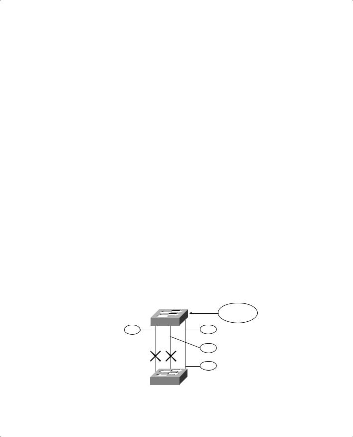
1.The Spanning Tree topology should look like the diagram in Figure 21-8. Catalyst A is the Root Bridge, and only the 1000-Mbps link is Forwarding. The Root Ports (RP) and Designated Ports (DP) are labeled on the diagram.
Figure 21-8 Resulting Spanning Tree Topology for Scenario 3
Catalyst A
32768.00-d0-58-a3-83-c9
|
|
|
Root Bridge |
DP |
fa1/2 |
g2/1 |
DP |
fa1/1 |
|
||
100 |
19 |
4 |
DP |
fa1/1 |
fa1/2 |
g2/1 |
RP |
Catalyst B 32768.00-d0-58-a3-83-ca

508Chapter 21: Scenarios for Final Preparation
2.Because the 100-Mbps link is in the Blocking state on Catalyst B, no major change in the topology occurs. Effectively, this link was already “disconnected.” However, after the physical link status goes down, both Catalyst A and Catalyst B sense the change and begin sending TCN BPDUs to notify each other of the topology change. Because Catalyst A is the Root Bridge, it acknowledges the TCN to Catalyst B. Both switches age out their MAC address tables in Forward Delay seconds.
3.Disconnecting the 1000-Mbps link causes Catalyst B to immediately find another Root Port. Ports 1/1 and 1/2 go into the Listening state, waiting to receive BPDUs. Port 1/2, with a cost of 19, become the next Root Port, as soon as Catalyst B computes the Root Path Cost (0+19) for it. Port 1/2 stays in the Listening state for Forward Delay (15 seconds), and then in the Learning state for Forward Delay (15 seconds). Port 1/2 moves into the Forwarding state, restoring connectivity in 30 seconds. (If PAgP is operating on the port, an additional delay of 20 seconds occurs.)
4.Because the 1000-Mbps link’s status stays up, neither Catalyst detects a link failure. Therefore, no immediate attempt to find another Root Port occurs. Instead, Catalyst B will not receive BPDUs from Catalyst A over link GigabitEthernet 2/1 because they are being filtered out. After the MaxAge Timer expires (20 seconds), Catalyst B ages out the stored BPDU for Catalyst A on port GigabitEthernet 2/1. Catalyst B moves ports FastEthernet 1/1 and 1/2 into the Listening state to determine a new Root Port. As in Step 3, port FastEthernet 1/2 becomes the Root Port with a lower Root Path Cost than port FastEthernet 1/1. The port moves through the Listening (15 seconds) and Learning (15 seconds) states and into the Forwarding state. The total time that has elapsed before connectivity restores is 20 + 15 + 15 = 50 seconds. (Again, if PAgP is active on the port, an additional 20 seconds can be added to the delay.)
Scenario 4 Answers
1.The Unidirectional Link Detection (UDLD) feature can be used. You can use the udld aggressive global configuration command to enable UDLD on all fiber-optic ports. UDLD must be enabled on both ends of a link, so it should be enabled on switches A1, as well as C1 and C2.
2.The spanning-tree portfast interface configuration command defines an edge port.
3.A minimum of two MST instances are needed so that traffic can be load-balanced. One instance can support VLANs 100 through 104, while the other can support VLANs 200 through 204. To load-balance, traffic from one instance must be carried over one uplink, while the other instance is carried over the second uplink.

Scenario 5 Answers 509
4.You can use these configuration commands:
spanning-tree mode mst spanning-tree mst configuration
name NorthWestDivision revision 1
instance 1 vlan 100,101,102,103,104,99 instance 2 vlan 200,201,202,203,204
exit
Notice that VLAN 99, used for switch management traffic, is also mapped to an MST instance. It is sometimes easy to forget about nonuser or nonaccess VLANs.
5.This command makes C1 become the MST Root Bridge for instance 1:
spanning-tree mst 1 root primary
This causes the uplink from C1 to A1 to be used for instance 1, by keeping it in the Forwarding state. Switch C2 should also be configured as the Root for MST instance 2 so that the other uplink can be used for those VLANs.
Scenario 5 Answers
1.You can configure HSRP load-balancing with the following Catalyst configuration commands:
interface vlan |
101 |
ip address 192.168.101.2 255.255.255.0 |
|
standby 101 |
priority 110 |
standby 101 |
preempt |
standby 101 |
ip 192.168.101.1 |
interface vlan |
102 |
ip address 192.168.102.2 255.255.255.0 |
|
standby 102 |
priority 100 |
standby 102 |
preempt |
standby 102 |
ip 192.168.102.1 |
The default gateway address that is shared between the switches is configured as 192.168.101.1 for VLAN 101 and 192.168.102.1 for VLAN 102. In VLAN 101, the virtual interface has an IP address of 192.168.101.2. Two HSRP groups are defined, one for each VLAN. Interface VLAN 101 will be the active router for VLAN 101, due to its higher priority of 110 (over a default of 100 on the other Catalyst). If control is passed to the standby router, this router can assume control again through the use of the preempt command. For VLAN 102, the roles are reversed. This router becomes the standby router in Group 102, with its lower priority of 100. (The other switch will be configured with priority 110 for VLAN 102 to take the active router role.)

510Chapter 21: Scenarios for Final Preparation
2.The four-part answers to Question 2 are as follows:
a.By default, all switches have a GLBP priority of 100. Catalyst B’s priority can be raised with the glbp 10 priority 200 command.
b.Only the AVG switch, Catalyst B, needs to be configured with the gateway address. It will inform all other members of the group. You should use the glbp 10 ip 192.168.10.1 command.
c.Glbp 10 load-balancing round-robin.
d.Each AVF switch should receive the glbp 10 ip interface configuration command. No IP address is needed here because the virtual gateway address is learned from the group’s AVG.
Scenario 6 Answers
1.With IGMP snooping, a switch can listen to IGMP activity for itself. Although this does burden the switch supervisor with examining IGMP reports from multicast group members, the learning process does not require a router or multilayer switch. However, if a switch does not have hardware capable of IGMP snooping natively, CGMP and help from an external router are required.
2.By default, a switch must forward broadcast and multicast frames out all available ports on a VLAN. The multicast traffic will be seen on all VLAN 101 ports on Catalyst A. In addition, Catalyst C and Catalyst D bridges the multicast traffic over the trunk links between them.
Finally, all VLAN 101 ports on Catalyst B also forwards the multicasts.
3.In this network, CGMP configuration is needed on both types of switches, whether IGMP snooping can be used or not. You can use the following commands on one of the multilayer switches:
ip multicast-routing interface vlan 101
ip pim dense-mode ip cgmp
interface vlan 102 ip pim dense-mode ip cgmp
On Catalyst A and B, only the following global configuration command cgmp is needed.
Scenario 7 Answers
1.The QoS domain should consist of the two Catalyst switches, A and B. QoS trust will be extended to the IP Phone connected to Catalyst B. QoS information should be trusted on the ports connecting switches A and B, along with the IP Phone port on switch B. QoS information

Scenario 7 Answers 511
should not be trusted on Catalyst A port 1/1 (the public network), Catalyst B port 3/2 (PC), or the IP Phone’s PC port. At these locations, incoming QoS information will be overwritten to known and trusted values.
2.You can use the following commands:
mls qos
interface gigabitethernet 1/1 no mls trust
mls qos cos 0
Here, QoS must first be enabled. Then, the interface is configured to have no trust. The overriding CoS value on the untrusted interface is set to 0, although this is already the default value.
3.The following commands can classify the traffic according to UDP port 5000 and Citrix. For Citrix, NBAR is used to match against the specific protocol definition for Citrix:
ip access-list extended apps permit udp any any eq 5000
class-map importantapp match-any match access-group name apps match protocol citrix
4.The following commands can define and apply the QoS policy:
policy-map apps-policy class importantapp set ip dscp 26
interface gigabitethernet 1/1 service-policy input apps-policy
5.No additional commands are needed, although it could be set with the set ip precedence 3 policy map command. This is because the IP Precedence field is actually the DSCP Class Selector field (the codepoint name’s first digit). In this case, the Class Selector for AF31 is 3. If you set one, the other is inherently set, too.
6.The following commands define VLAN 17 as the voice VLAN (VVID) and the IP Phone’s data port as untrusted:
interface fastethernet 3/1 switchport voice vlan 17 switchport priority extend cos 0
7.For the Skinny protocol, the voice bearer traffic (CoS 5, using RTP) will be placed in the strict priority egress queue on the interface. This is the queue referenced by the “1p” label and is queue number 3. Call control traffic (CoS 3) will be placed in a high-priority standard queue, referenced by the “q” label.

512 Chapter 21: Scenarios for Final Preparation
Scenario 8 Answers
1.On a Catalyst 3550, you can use the following commands:
interface range fastethernet 0/1 – 48 switchport port-security
2.On a Catalyst 3550, you can use the following commands:
interface fastethernet 0/18 switchport port-security switchport port-security maximum 24
switchport port-security violation restrict
The first command line enables port-level security on the switch port. The second line configures port security to learn up to 24 MAC addresses dynamically on that port. The last line configures the switch to restrict any MAC addresses found to be in violation (any additional addresses learned beyond the 24). The port stays up, allowing the other users to communicate.
3.You can use the following commands:
access-list 101 permit tcp 192.168.191.0 0.0.0.255 host 192.168.191.199 eq www
vlan access-map myfilter match ip address 101 action forward
match action drop
vlan filter myfilter vlan-list 180
The first line configures an access list that will be used only to match against traffic being forwarded on a VLAN. The permit keyword only causes matching traffic to be eligible for an action by the VACL—it does not cause the matching traffic to be forwarded or not. The VACL is configured to first match traffic with access list 101; this traffic is forwarded as normal. Then, a simple match statement is given so that all other traffic is matched; this remaining traffic is dropped so that it does not reach its destination. The VACL is then applied to VLAN 180.
4.The following commands can configure a local SPAN session on the Catalyst 6500:
monitor session 1 source interface gigabitethernet 3/3 both monitor session 1 destination interface gigabitethernet 5/8
5.The only potential problem is with the mismatch in connection speeds. The server has a GigabitEthernet connection, while the analyzer is limited by its FastEthernet connection. If the server has a low utilization on its connection, the network analysis might turn out fine. Otherwise, if the server’s connection is using most of the available 1000 Mbps of bandwidth, the analyzer misses a large portion of the mirrored packets.
The server and its connection will not suffer from the speed mismatch. The Catalyst switch continues to forward packets to and from the server as if no port mirroring was occurring. It is only when the packets are being copied over to the monitor port queue that they can potentially be dropped.


PART VI: Appendix
Appendix A Answers to Chapter “Do I Know This Already?” Quizzes and Q&A Sections

Each chapter begins with a “Do I Know This Already?” quiz that helps you determine the amount of time you need to spend studying that chapter. In addition, each chapter ends with a “Q&A” section that provides mostly open-ended, rather than multiple-choice, questions as found on the exams. This helps you focus more on understanding the subject matter than on memorizing details. This appendix enables you to verify your answers for both; use it as a study sheet when your exam looms closer.