CCNP 642-811 BCMSN Exam Certification Guide - Cisco press
.pdf286 Chapter 12: Advanced Spanning Tree Protocol
Port Types
Every switch port can be considered one of the following types:
■Edge Port—A port at the “edge” of the network, where only a single host connects. Traditionally, this has been identified by enabling the STP PortFast feature. RSTP keeps the PortFast concept for familiarity. By definition, the port cannot form a loop as it connects to one host, so it can be immediately placed in the Forwarding state. However, if a BPDU is ever received on an edge port, the port immediately loses its edge port status.
■Root Port—The port that has the best cost to the root of the STP instance. Only one Root Port can be selected and active at any time, although alternate paths to the root can exist through other ports. If alternate paths are detected, those ports are identified as Alternate Root Ports and can be immediately placed in the Forwarding state when the existing Root Port fails.
■Point-to-Point Port—Any port that connects to another switch and becomes a Designated Port. A quick handshake with the neighboring switch, rather than a timer expiration, decides the port state. BPDUs are exchanged back and forth in the form of a proposal and an agreement. One switch proposes that its port becomes a Designated Port; if the other switch agrees, it replies with an agreement message.
Point-to-point ports are automatically determined by the duplex mode in use. Full-duplex ports are considered point-to-point because only two switches can be present on the link. STP convergence can quickly occur over a point-to-point link through RSTP handshake messages.
Half-duplex ports, on the other hand, are considered to be on a shared media with possibly more than two switches present. They are not point-to-point ports. STP convergence on a half-duplex port must occur between several directly connected switches. Therefore, the traditional 802.1D style convergence must be used. This results in a slower response because the shared-media ports must go through the fixed listening and learning state time periods.
It’s easy to see how two switches can quickly converge to a common idea of which one is the Root and which one will have the Designated Port after just a single exchange of BPDUs. What about a larger network, where 802.1D BPDUs would normally have to be relayed from switch to switch?
RSTP handles the complete STP convergence of the network as a propagation of handshakes over point-to-point links. When a switch needs to make an STP decision, a handshake is made with the nearest neighbor. After that is successful, the handshake sequence is moved to the next switch and the next, as an ever-expanding wave moving toward the network’s edges.
During each handshake sequence, a switch must take measures to be completely sure it will not introduce a bridging loop before moving the handshake out. This is done through a synchronization process.

Rapid Spanning Tree Protocol (RSTP) 287
Synchronization
To participate in RSTP convergence, a switch must decide the state of each of its ports. Nonedge ports begin in the Discarding state. After BPDUs are exchanged between the switch and its neighbor, the Root Bridge can be identified. If a port receives a superior BPDU from a neighbor, that port becomes the Root Port.
For each nonedge port, the switch exchanges a proposal-agreement handshake to decide the state of each end of the link. Each switch assumes that its port should become the Designated Port for the segment, and a proposal message (a Configuration BPDU) is sent to the neighbor suggesting this.
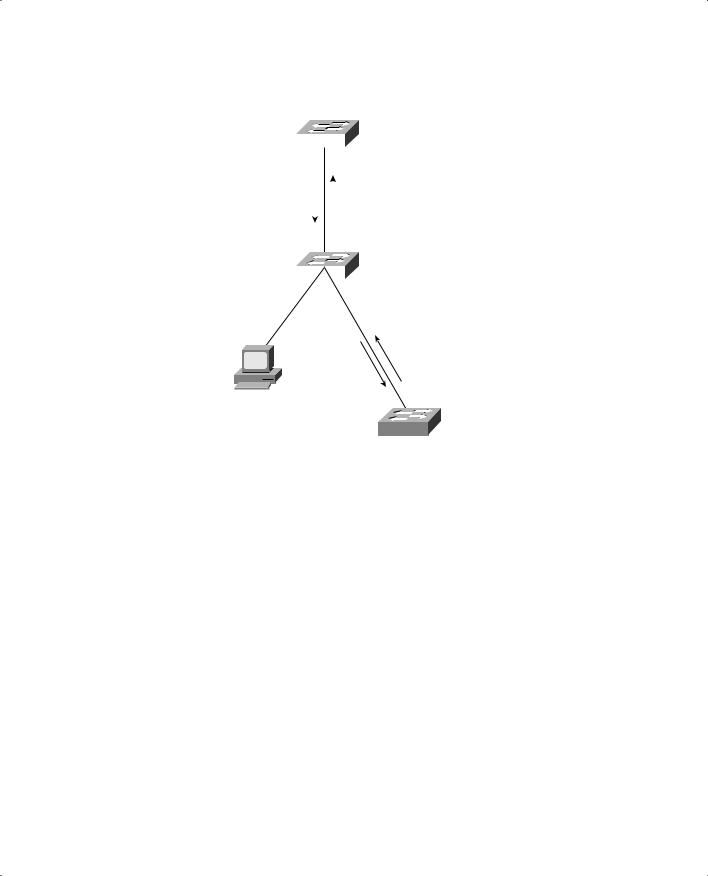
When a switch receives a proposal message on a port, the following sequence of events occurs (Figure 12-1 shows the sequence, based around the center Catalyst switch):
1.If the proposal’s sender has a superior BPDU, the local switch realizes that the sender should be the Designated Switch (having the Designated Port), and that its own port must become the new Root Port.
2.Before the switch agrees to anything, it must first synchronize itself with the topology.
3.All nonedge ports are immediately moved into the Discarding (blocking) state so that no bridging loops can form.
4.An agreement message (a Configuration BPDU) is sent back to the sender, indicating that the switch is in agreement with the new Designated Port choice. This also tells the sender that the switch is in the process of synchronizing itself.
5.The Root Port is immediately moved to the Forwarding state. The sender’s port can also immediately begin forwarding.
6.For each nonedge port that is currently in the Discarding state, a proposal message is sent to the respective neighbor.
7.An agreement message is expected and received from a neighbor on a nonedge port.
8.The nonedge port is immediately moved to the Forwarding state.
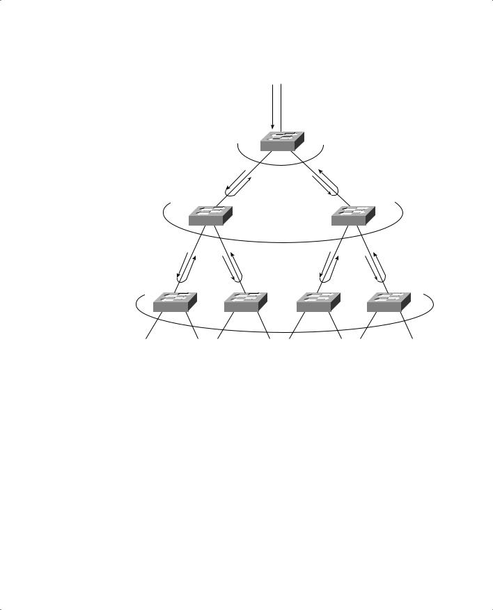
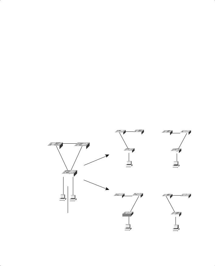
Notice how the RSTP convergence begins with a switch sending a proposal message. The recipient of the proposal must synchronize itself by effectively isolating itself from the rest of the topology. All nonedge ports are blocked until a proposal message can be sent, causing the nearest neighbors to synchronize themselves. This creates a moving “wave” of synchronizing switches, which can quickly decide to start forwarding on their links only if their neighbors agree. Figure 12-2 shows how the synchronization wave travels through a network at three successive time intervals. Isolating the switches along the traveling wave inherently prevents bridging loops.
288 Chapter 12: Advanced Spanning Tree Protocol
Figure 12-1 Sequence of Events During RSTP Convergence
|
|
|
|
|
|
|
|
|
|
5. Forward |
|||
|
1. Proposal |
|
4. Agreement |
|||
|
|
|||||
|
|
|||||
|
|
|
|
|
||
|
|
|
|
|
||
|
|
|
5. Forward |
|||
Catalyst |
2. Sync! |
|
|
|
|
|
Switch |
|
|
|
|
|
|
|
|
|
|
|
|
|
|
|
|
|
X |
3. Block |
|
|
|
|
|
|
|
|
|
Edge Port |
|
|
|
8. Forward |
|
7. Agreement
6. Proposal |
Point-to-Point |
|
The entire convergence process happens quickly, at the speed of BPDU transmission, without the use of any timers. A Designated Port that sends a proposal message might not receive an agreement message reply. Suppose the neighboring switch does not understand RSTP or has a problem replying. The sending switch must then become overly cautious and begin playing by the 802.1D rules— the port must be moved through the legacy Listening and Learning states (using the Forward Delay timer) before moving to the Forwarding state.
Topology Changes and RSTP
Recall that when an 802.1D switch detects a port state change (either up or down), it signals the Root Bridge by sending topology change notification (TCN) BPDUs. The Root Bridge must then signal a topology change by sending out a TCN message that is relayed to all switches in the STP domain.
RSTP detects a topology change only when a nonedge port transitions to the Forwarding state. This might seem odd because a link failure is not used as a trigger. RSTP uses all of its rapid convergence mechanisms to prevent bridging loops from forming. Therefore, topology changes are detected only so that bridging tables can be updated and corrected as hosts appear first on a failed port and then on a different functioning port.

290 Chapter 12: Advanced Spanning Tree Protocol
RSTP Configuration
By default, a switch operates in the Per VLAN Spanning Tree Plus (PVST+) mode using traditional 802.1D STP. Therefore, RSTP cannot be used until a different Spanning Tree mode (MST or RPVST+) is enabled. Remember that RSTP is just the underlying mechanism that a Spanning Tree mode can use to detect topology changes and converge a network into a loop-free topology.
The only configuration changes related to RSTP affect the port or link type. The link type is used to determine how a switch negotiates topology information with its neighbors.
To configure a port as an RSTP edge port, use the following interface configuration command:
Switch(config-if)# spanning-tree portfast
You should already be familiar with this command from the 802.1D STP configuration. After PortFast is enabled, the port is considered to have only one host and is positioned at the edge of the network.
By default, RSTP automatically decides that a port is a point-to-point link if it is operating in fullduplex mode. Ports connecting to other switches are usually full-duplex because there are only two switches on the link. However, you can override the automatic determination if needed. For example, a port connecting to one other switch might be operating at half-duplex for some reason. To force the port to act as a point-to-point link, use the following interface configuration command:
Switch(config-if)# spanning-tree link-type point-to-point
Multiple Spanning Tree (MST) Protocol
Chapter 9 covered two “flavors” of Spanning Tree implementations—IEEE 802.1Q and PVST+— both based on the 802.1D STP. These also represent the two extremes of Spanning Tree Protocol operation in a network:
■802.1Q—Only a single instance of STP is used for all VLANs. If there are 500 VLANs, only one instance of STP will be running. This is called the Common Spanning Tree (CST) and operates over the trunk’s native VLAN.
■PVST+—One instance of STP is used for each active VLAN in the network. If there are 500 VLANs, 500 independent instances of STP will be running.
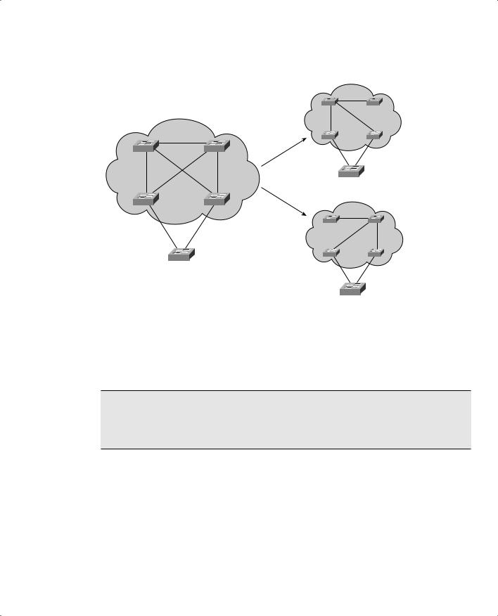
In most networks, each switch has a redundant path to another switch. For example, an access layer switch usually has two uplinks, each connecting to a different distribution or core layer switch. If 802.1Q’s CST is used, only one STP instance will run. That means there is only one loop-free topology at any given time, and that only one of the two uplinks in the access layer switch will be forwarding. The other uplink will always be blocking.

292 Chapter 12: Advanced Spanning Tree Protocol
Notice also that the number of useful topologies is independent of the number of VLANs. If 10 or 100 VLANs were used in the figure, there would still be only two possible outcomes at the access layer switch. Therefore, running 10 or 100 instances of STP when only a couple would suffice is rather wasteful.
The Multiple Spanning Tree Protocol (MST or MSTP) was developed to address the lack of and surplus of STP instances. As a result, the network administrator can configure exactly the number of STP instances that make sense for the enterprise network—no matter how many VLANs are in use. MST is defined in the IEEE 802.1s standard.
MST Overview
MST is built on the concept of mapping one or more VLANs to a single STP instance. Multiple instances of STP can be used (hence the name MST), with each instance supporting a different group of VLANs.
For the network shown in Figure 12-3, only two MST instances would be needed. Each could be tuned to result in a different topology, so that Instance 1 would forward on the left uplink, while Instance 2 would forward on the right uplink. Therefore, VLAN A would be mapped to Instance 1, and VLAN B to Instance 2.
To implement MST in a network, you need to determine the following:
■The number of STP instances needed to support the desired topologies.
■Whether to map a set of VLANs to each instance.
MST Regions
MST is different than 802.1Q and PVST+, although it can interoperate with them. If a switch is configured to use MST, it must somehow figure out which of its neighbors are using which type of STP. This is done by configuring switches into common MST regions, where every switch in a region runs MST with compatible parameters.
In most networks, a single MST region is sufficient, although you can configure more than one region. Within the region, all switches must run the instance of MST that is defined by the following attributes:
■MST configuration name (32 characters)
■MST configuration revision number (0 to 65535)
■MST instance-to-VLAN mapping table (4096 entries)

Multiple Spanning Tree (MST) Protocol 293
If two switches have the same set of attributes, they belong to the same MST region. If not, they belong to two independent regions.
MST BPDUs contain configuration attributes so that switches receiving BPDUs can compare them against their local MST configurations. If the attributes match, the STP instances within MST can be shared as part of the same region. If not, a switch is seen to be at the MST region boundary, where one region meets another or one region meets traditional 802.1D STP.
NOTE The entire MST instance-to-VLAN mapping table is not sent along in the BPDUs because the instance mappings must be configured on each switch. Instead, a digest, or a code computed from the table contents, is sent. As the contents of the table change, the digest value will be different. Therefore, a switch can quickly compare a received digest to its own to see if the advertised table is the same or different.
Spanning Tree Instances Within MST
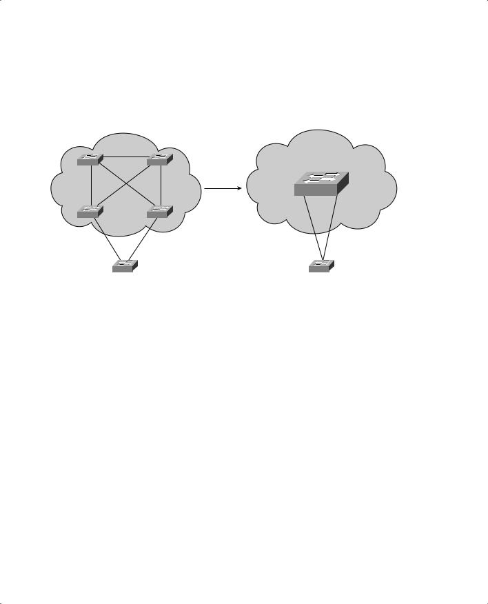
MST was designed to interoperate with all other forms of STP. Therefore, it must also support STP instances from each. This is where MST can get confusing. Think of the entire enterprise network having a single CST topology, such that one instance of STP represents any and all VLANs and MST regions present. The CST serves to maintain a common loop-free topology, while integrating all forms of STP that might be in use.
To do this, CST must regard each MST region as a single “black box” bridge because it has no idea what is inside the region, nor does it care. CST only maintains a loop-free topology with the links that connect the regions to each other and to standalone switches running 802.1Q CST.
IST Instances
Something other than CST must work out a loop-free topology inside each MST region. Within a single MST region, an Internal Spanning Tree (IST) instance runs to work out a loop-free topology between the links where CST meets the region boundary and all switches inside the region. Think of the IST instance as a locally significant CST, bounded by the edges of the region.
The IST presents the entire region as a single virtual bridge to the CST outside. BPDUs are exchanged at the region boundary only over the native VLAN of trunks, as if a single CST were in operation. And, indeed, it is.
Figure 12-4 shows the basic concept behind the IST instance. The network at the left has an MST region, where several switches are running compatible MST configurations. Another switch is outside the region because it is running only the CST from 802.1Q.