

CCNP 642-811 BCMSN Exam Certification Guide - Cisco press
.pdf216 Chapter 9: Traditional Spanning Tree Protocol
Step 2 Because PC-4’s location is unknown, both switches forward the frame out all available ports (their 2/1 ports) and onto Segment B.
Step 3 Each switch places a new frame on its 2/1 port on Segment B. PC-4, located on Segment B, receives the two frames destined for it. However, Switch A hears the new frame forwarded by Switch B, and Switch B hears the new frame forwarded by Switch A.
Step 4 Switch A sees that the “new” frame is from PC-1 to PC-4. From the address table, the switch had learned that PC-1 was on port 1/1, or Segment A. However, PC-1’s source address has just been heard on port 2/1 on Segment B. By definition, the switch must relearn PC-1’s location, which is now incorrectly assumed to be Segment B. (Switch B follows the same procedure, based on the “new” frame from Switch A.)
Step 5 At this point, neither Switch A nor Switch B has learned PC-4’s location because no frames have been received with PC-4 as the source address. Therefore, the frame must be forwarded out all available ports in an attempt to find PC-4. This frame is then sent out Switch A’s 1/1 port and onto Segment A.
Step 6 Now, both switches relearn PC-1’s location as Segment A and forward the “new” frames back onto Segment B; then the entire process repeats.
This process of forwarding a single frame around and around between two switches is known as a bridging loop. Neither switch is aware of the other, so each happily forwards the same frame back and forth between its segments. Also note that because two switches are involved in the loop, the original frame has been duplicated and now is sent around in two counter-rotating loops. What stops the frame from being forwarded in this fashion forever? Nothing. PC-4 begins receiving frames addressed to it as fast as the switches can forward them.
Notice how the PCs’ learned location keeps changing as frames get looped. Even a unicast frame has caused a bridging loop to form, and each switch’s bridge table is repeatedly corrupted with incorrect data.
What would happen if PC-1 sent a broadcast frame instead? The bridging loops (remember that two of them are produced by the two parallel switches) form exactly as before. The broadcast frames continue to circulate forever. Now, however, every end-user device located on both Segments A and B receives and processes each and every broadcast frame. This type of broadcast storm can easily saturate the network segments and bring every host on the segments to a halt.
The only way to end the bridging loop is to physically break the loop by disconnecting switch ports or shutting a switch down. Obviously, preventing bridging loops rather than be faced with breaking them after they form would be better.

IEEE 802.1D Overview 217
Preventing Loops with Spanning Tree Protocol
Bridging loops form because parallel switches (or bridges) are unaware of each other. STP was developed to overcome the possibility of bridging loops so that redundant switches and switch paths could be used for their benefits. Basically, the protocol enables switches to become aware of each other so they can negotiate a loop-free path through the network.
NOTE Because STP is involved in loop detection, many people refer to the catastrophic loops as “Spanning Tree loops.” This is technically incorrect, as the Spanning Tree Protocol’s entire function is to prevent bridging loops. The correct terminology for this condition is a bridging loop.
Loops are discovered before they are made available for use, and redundant links are shut down to prevent the loops from forming. In the case of redundant links, switches can be made aware that a link shut down for loop prevention should be quickly brought up in case of a link failure. This is discussed in later sections of this chapter.
STP is communicated between all connected switches on a network. Each switch executes the Spanning Tree Algorithm based on information received from other neighboring switches. The algorithm chooses a reference point in the network and calculates all the redundant paths to that reference point. When redundant paths are found, the Spanning Tree Algorithm picks one path by which to forward frames and disables, or blocks, forwarding on the other redundant paths.
As its name implies, STP computes a tree structure that spans all switches in a subnet or network. Redundant paths are placed in a Blocking or Standby state to prevent frame forwarding. The switched network is then in a loop-free condition. However, if a forwarding port fails or becomes disconnected, the Spanning Tree Algorithm recomputes the Spanning Tree topology so that blocked links can be reactivated.
Spanning Tree Communication: Bridge Protocol Data Units
STP operates as switches communicate with one another. Data messages are exchanged in the form of Bridge Protocol Data Units (BPDUs). A switch sends a BPDU frame out a port, using the unique MAC address of the port itself as a source address. The switch is unaware of the other switches around it. Therefore, the BPDU frame has a destination address of the well-known STP multicast address 01-80-c2-00-00-00 to reach all listening switches.
Two types of BPDU exist:
■Configuration BPDU, used for Spanning Tree computation
■Topology Change Notification (TCN) BPDU, used to announce changes in the network topology

218 Chapter 9: Traditional Spanning Tree Protocol
The Configuration BPDU message contains the fields shown in Table 9-2. The TCN BPDU is discussed in the “Topology Changes” section later in this chapter.
Table 9-2 Configuration BPDU Message Content
Field Description |
Number of Bytes |
|
|
Protocol ID (always 0) |
2 |
|
|
Version (always 0) |
1 |
|
|
Message Type (Configuration or TCN BPDU) |
1 |
|
|
Flags |
1 |
|
|
Root Bridge ID |
8 |
|
|
Root Path Cost |
4 |
|
|
Sender Bridge ID |
8 |
|
|
Port ID |
2 |
|
|
Message Age (in 256ths of a second) |
2 |
|
|
Maximum Age (in 256ths of a second) |
2 |
|
|
Hello Time (in 256ths of a second) |
2 |
|
|
Forward Delay (in 256ths of a second) |
2 |
|
|
The exchange of BPDU messages works toward the goal of electing reference points as a foundation for a stable Spanning Tree topology. Loops can also be identified and removed by placing specific redundant ports in a Blocking or Standby state. Notice that several key fields in the BPDU are related to bridge (or switch) identification, path costs, and timer values. These all work together so that the network of switches can converge upon a common Spanning Tree topology and select the same reference points within the network. These reference points are defined in the sections that follow.
BPDUs are sent out all switch ports every two seconds so that current topology information is exchanged and loops are identified quickly.
Electing a Root Bridge
For all switches in a network to agree on a loop-free topology, a common frame of reference must exist to use as a guide. This reference point is called the Root Bridge. (The term “bridge” continues to be used even in a switched environment because STP was developed for use in bridges. Therefore, when you see “bridge,” think “switch.”)

IEEE 802.1D Overview 219
An election process among all connected switches chooses the Root Bridge. Each switch has a unique Bridge ID that identifies it to other switches. The Bridge ID is an 8-byte value consisting of the following fields:
■Bridge Priority (2 bytes)—The priority or weight of a switch in relation to all other switches. The priority field can have a value of 0 to 65,535 and defaults to 32,768 (or 0x8000) on every Catalyst switch.
■MAC Address (6 bytes)—The MAC address used by a switch can come from the Supervisor module, the backplane, or a pool of 1024 addresses that are assigned to every Supervisor or backplane depending on the switch model. In any event, this address is hardcoded and unique, and the user cannot change it.
When a switch first powers up, it has a narrow view of its surroundings and assumes that it is the Root Bridge itself. This notion will probably change as other switches check in and enter the
election process. The election process then proceeds as follows: Every switch begins by sending out BPDUs with a Root Bridge ID equal to its own Bridge ID and a Sender Bridge ID of its own Bridge ID. The Sender Bridge ID simply tells other switches who is the actual sender of the BPDU message. (After a Root Bridge is decided upon, configuration BPDUs are only sent by the Root Bridge. All other bridges must forward or relay the BPDUs, adding their own Sender Bridge IDs to the message.)
Received BPDU messages are analyzed to see if a “better” Root Bridge is being announced. A Root Bridge is considered better if the Root Bridge ID value is lower than another. Again, think of the Root Bridge ID as being broken up into Bridge Priority and MAC address fields. If two Bridge Priority values are equal, the lower MAC address makes the Bridge ID better. When a switch hears of a better Root Bridge, it replaces its own Root Bridge ID with the Root Bridge ID announced in the BPDU. The switch is then required to recommend or advertise the new Root Bridge ID in its own BPDU messages; although, it will still identify itself as the Sender Bridge ID.
Sooner or later, the election converges and all switches agree on the notion that one of them is the Root Bridge. As might be expected, if a new switch with a lower Bridge Priority powers up, it begins advertising itself as the Root Bridge. Because the new switch does indeed have a lower Bridge ID, all the switches will soon reconsider and record it as the new Root Bridge. This can also happen if the new switch has a Bridge Priority equal to the existing Root Bridge but a lower MAC address.
Root Bridge election is an ongoing process, triggered by Root Bridge ID changes in the BPDUs every two seconds.
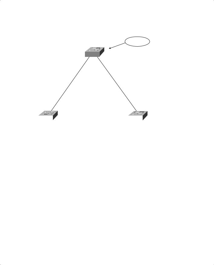
As an example, consider the small network shown in Figure 9-3. For simplicity, assume that each Catalyst switch has a MAC address of all 0s with the last hex digit equal to the switch label.
220 Chapter 9: Traditional Spanning Tree Protocol
Figure 9-3 Example of Root Bridge Election
Catalyst A
Root Bridge
32768.00-00-00-00-00-0a
1/1 |
1/2 |
100 Mbps |
100 Mbps |
Cost = 19 |
Cost = 19 |
1/1 |
|
|
100 Mbps |
1/1 |
|||
|
|
|
|
Cost = 19 |
|
|
|
|
|
|
|
|
|
|
|
|
|
1/2 |
|
1/2 |
|
|
|
|
|
|
|
|
|||
|
Catalyst B |
|
|
Catalyst C |
|||
32768.00-00-00-00-00-0b |
|
32768.00-00-00-00-00-0c |
|||||
In this network, each switch has the default Bridge Priority of 32,768. The switches are interconnected with FastEthernet links, having a default path cost of 19. All three switches try to elect themselves as the Root, but all of them have equal Bridge Priority values. The election is determined by the lowest MAC address—that of Catalyst A.
Electing Root Ports
Now that a reference point has been nominated and elected for the entire switched network, each nonroot switch must figure out where it is in relation to the Root Bridge. This action can be performed by selecting only one Root Port on each nonroot switch.
STP uses the concept of cost to determine many things. Selecting a Root Port involves evaluating the Root Path Cost. This value is the cumulative cost of all the links leading to the Root Bridge. A particular switch link has a cost associated with it, too, called the Path Cost. To understand the difference between these values, remember that only the Root Path Cost is carried inside the BPDU. (See Table 9-2 again.) As the Root Path Cost travels along, other switches can modify its value to make it cumulative. The Path Cost, however, is not contained in the BPDU. It is known only to the local switch where the port (or “path” to a neighboring switch) resides.

IEEE 802.1D Overview 221
Path Costs are defined as a 1-byte value, with the default values shown in Table 9-3. Generally, the higher the bandwidth of a link, the lower the cost of transporting data across it. The original IEEE 802.1D standard defined Path Cost as 1000 Mbps divided by the link bandwidth in Mbps. These values are shown in the center column of the table. Modern networks commonly use GigabitEthernet and OC-48 ATM, which are both either too close to or greater than the maximum scale of 1000 Mbps. The IEEE now uses a nonlinear scale for Path Cost, as shown in the right column of the table.
TIP Be aware that there are two STP path cost scales—one that is little used with a linear scale and one commonly used that is nonlinear. If you decide to memorize some common Path Cost values, learn only the ones in the “new” righthand column of the table.
Table 9-3 STP Path Cost
Link Bandwidth |
Old STP Cost |
New STP Cost |
|
|
|
4 Mbps |
250 |
250 |
|
|
|
10 Mbps |
100 |
100 |
|
|
|
16 Mbps |
63 |
62 |
|
|
|
45 Mbps |
22 |
39 |
|
|
|
100 Mbps |
10 |
19 |
|
|
|
155 Mbps |
6 |
14 |
|
|
|
622 Mbps |
2 |
6 |
|
|
|
1 Gbps |
1 |
4 |
|
|
|
10 Gbps |
0 |
2 |
|
|
|
The Root Path Cost value is determined in the following manner:
1.The Root Bridge sends out a BPDU with a Root Path Cost value of 0 because its ports sit directly on the Root Bridge.
2.When the next-closest neighbor receives the BPDU, it adds the Path Cost of its own port where the BPDU arrived. (This is done as the BPDU is received.)
3.The neighbor sends out BPDUs with this new cumulative value as the Root Path Cost.
4.This value is added to by subsequent switch port Path Costs as each switch receives the BPDU on down the line.

222 Chapter 9: Traditional Spanning Tree Protocol
NOTE Notice the emphasis on incrementing the Root Path Cost as BPDUs are received. When computing the Spanning Tree Algorithm manually, remember to compute a new Root Path Cost as BPDUs come in to a switch port—not as they go out.
After incrementing the Root Path Cost, a switch also records the value in its memory. When a BPDU is received on another port and the new Root Path Cost is lower than the previously recorded value, this lower value becomes the new Root Path Cost. In addition, the lower cost tells the switch that the path to the Root Bridge must be better using this port than it was on other ports. The switch has now determined which of its ports has the best path to the Root—the Root Port.
Figure 9-4 shows the same network from Figure 9-3 in the process of Root Port selection.
Figure 9-4 Example of Root Port Selection
Catalyst A
Root Bridge
32768.00-00-00-00-00-0a
1/1 |
1/2 |
|
100 Mbps |
|
100 Mbps |
|
||||
|
Cost = 19 |
|
Cost = 19 |
|
||||
Root Port |
|
|
|
|
|
|
|
Root Port |
Root Path Cost = 19 |
1/1 |
|
|
100 Mbps |
1/1 |
Root Path Cost = 19 |
||
|
|
|
|
Cost = 19 |
|
|
|
|
|
|
|
|
|
|
|
|
|
|
|
1/2 |
|
1/2 |
|
|
|
|
|
|
|
|
|
|
|||
|
Catalyst B |
|
|
Catalyst C |
|
|||
32768.00-00-00-00-00-0b |
|
32768.00-00-00-00-00-0c |
||||||
(Root Path Cost = 19 + 19)
The Root Bridge, Catalyst A, has already been elected. Therefore, every other switch in the network must choose one port that has the best path to the Root Bridge. Catalyst B selects its port 1/1, with a Root Path Cost of 0 plus 19. Port 1/2 is not chosen because its Root Path Cost is 0 (BPDU from Catalyst A) plus 19 (Path Cost of A-C link) plus 19 (Path Cost of C-B link), or a total of 38. Catalyst C makes a similar choice of port 1/1.

IEEE 802.1D Overview 223
Electing Designated Ports
By now, you should begin to see the process unfolding: a starting or reference point has been identified, and each switch “connects” itself toward the reference point with the single link that has the best path. A tree structure is beginning to emerge, but links have been identified only at this point. All links are still connected and could be active, leaving bridging loops.
To remove the possibility of bridging loops, STP makes a final computation to identify one Designated Port on each network segment. Suppose that two or more switches have ports connected to a single common network segment. If a frame appears on that segment, all the bridges attempt to forward it to its destination. Recall that this behavior was the basis of a bridging loop and should be avoided.
Instead, only one of the links on a segment should forward traffic to and from that segment. This location is the Designated Port. Switches choose a Designated Port based on the lowest cumulative Root Path Cost to the Root Bridge. For example, a switch always has an idea of its own Root Path Cost, which it announces in its own BPDUs. If a neighboring switch on a shared LAN segment sends a BPDU announcing a lower Root Path Cost, the neighbor must have the Designated Port. If a switch learns only of higher Root Path Costs from other BPDUs received on a port, however, it then correctly assumes that its own receiving port is the Designated Port for the segment.
Notice that the entire STP determination process has served only to identify bridges and ports. All ports are still active, and bridging loops might still lurk in the network. STP has a set of progressive states that each port must go through, regardless of the type or identification. These states actively prevent loops from forming and are described in the next section.
NOTE In each determination process discussed so far, two or more links having identical Root Path Costs is possible. This results in a tie condition, unless other factors are considered. All STP decisions are based on the following sequence of four conditions:
1.Lowest Root Bridge ID
2.Lowest Root Path Cost to Root Bridge
3.Lowest Sender Bridge ID
4.Lowest Sender Port ID
Figure 9-5 demonstrates an example of Designated Port selection. This figure is identical to Figure 9-3 and Figure 9-4, with further Spanning Tree development. The only changes shown are the choices of Designated Ports, although seeing all STP decisions shown in one network diagram is handy.

224 Chapter 9: Traditional Spanning Tree Protocol
Figure 9-5 Example of Designated Port Selection
|
|
Root Bridge |
|
|
Designated |
|
Catalyst A |
Designated |
|
Port |
32768.00-00-00-00-00-0a |
Port |
||
Root Path Cost = 0 |
|
|
|
Root Path Cost = 0 |
|
1/1 |
|
1/2 |
|
|
|
|
||
|
100 Mbps |
|
100 Mbps |
|
||||
|
Cost = 19 |
|
Cost = 19 |
|
||||
Root Port |
|
|
|
|
|
|
|
Root Port |
Root Path Cost = 19 |
1/1 |
|
|
100 Mbps |
1/1 |
Root Path Cost = 19 |
||
|
|
|
|
Cost = 19 |
X |
|
|
|
|
|
|
|
|
|
|
|
|
|
|
1/2 |
|
1/2 |
|
|
|
|
|
|
|
|
|
|
|||
|
Catalyst B |
|
|
Catalyst C |
|
|||
32768.00-00-00-00-00-0b |
Designated |
32768.00-00-00-00-00-0c |
||||||
|
|
|
|
|
|
|
|
|
|
|
|
|
Port |
|
|
|
|
Both Root Path Cost = 19
Catalyst B has lowest Bridge ID
The three switches have chosen their Designated Ports (DP) for the following reasons:
■Catalyst A—Because this switch is the Root Bridge, all its active ports are Designated Ports by definition. At the Root Bridge, the Root Path Cost of each port is 0.
■Catalyst B—Catalyst A port 1/1 is the DP for the Segment A-B because it has the lowest Root Path Cost (0). Catalyst B port 1/2 is the DP for segment B-C. The Root Path Cost for each end of this segment is 19, determined from the incoming BPDU on port 1/1. Because the Root Path Cost is equal on both ports of the segment, the DP must be chosen by the next criteria—the lowest Sender Bridge ID. When Catalyst B sends a BPDU to Catalyst C, it has the lowest MAC address in the Bridge ID. Catalyst C also sends a BPDU to Catalyst B, but its Sender Bridge ID is higher. Therefore, Catalyst B port 1/2 is selected as the segment’s DP.

IEEE 802.1D Overview 225
■Catalyst C—Catalyst A port 1/2 is the DP for Segment A-C because it has the lowest Root Path Cost (0). Catalyst B port 1/2 is the DP for Segment B-C. Therefore, Catalyst C port 1/2 will be neither a Root Port nor a Designated Port. As discussed in the next section, any port that is not elected to either position enters the Blocking state. Where blocking occurs, bridging loops are broken.
STP States
To participate in STP, each port of a switch must progress through several states. A port begins its life in a Disabled state, moving through several passive states and, finally, into an active state if allowed to forward traffic. The STP port states are as follows:
■Disabled—Ports that are administratively shut down by the network administrator, or by the system due to a fault condition, are in the Disabled state. This state is special and is not part of the normal STP progression for a port.
■Blocking—After a port initializes, it begins in the Blocking state so that no bridging loops can form. In the Blocking state, a port cannot receive or transmit data and cannot add MAC addresses to its address table. Instead, a port is allowed to receive only BPDUs so that the switch can hear from other neighboring switches. In addition, ports that are put into standby mode to remove a bridging loop enter the Blocking state.
■Listening—The port will be moved from Blocking to Listening if the switch thinks that the port can be selected as a Root Port or Designated Port. In other words, the port is on its way to begin forwarding traffic. In the Listening state, the port still cannot send or receive data frames.
However, the port is allowed to receive and send BPDUs so that it can actively participate in the Spanning Tree topology process. Here, the port is finally allowed to become a Root Port or Designated Port because the switch can advertise the port by sending BPDUs to other switches. Should the port lose its Root Port or Designated Port status, it returns to the Blocking state.
■Learning—After a period of time called the Forward Delay in the Listening state, the port is allowed to move into the Learning state. The port still sends and receives BPDUs as before. In addition, the switch can now learn new MAC addresses to add to its address table. This gives the port an extra period of silent participation and allows the switch to assemble at least some address table information.
■Forwarding—After another Forward Delay period of time in the Learning state, the port is allowed to move into the Forwarding state. The port can now send and receive data frames, collect MAC addresses in its address table, and send and receive BPDUs. The port is now a fully functioning switch port within the Spanning Tree topology.
NOTE Remember that a switch port is allowed into the Forwarding state only if no redundant links (or loops) are detected and if the port has the best path to the Root Bridge as the Root Port or Designated Port.