CCNP 642-811 BCMSN Exam Certification Guide - Cisco press
.pdf356Chapter 15: Multicast
10.What router maintains the RP-to-group correlation for Auto-RP in PIMv1?
a.RP agent
b.PIM root
c.Mapping agent
d.RP discovery server
11.What router advertises candidate RP routers in PIMv2?
a.Auto-RP
b.Mapping agent
c.Bootstrap router
d.PIM root
12.Which of the following methods requires a router to assist a Layer 2 switch in constraining multicast traffic?
a.PIM
b.IGMP
c.CGMP
d.IGMP snooping
You can find the answers to the “Do I Know This Already?” quiz in Appendix A, “Answers to Chapter ‘Do I Know This Already?’ Quizzes and Q&A Sections.” The suggested choices for your next step are as follows:
■10 or less overall score—Read the entire chapter. This includes the “Foundation Topics,” “Foundation Summary,” and “Q&A” sections.
■11 or 12 overall score—If you want more review on these topics, skip to the “Foundation Summary” section and then go to the “Q&A” section at the end of the chapter. Otherwise, move to Chapter 16, “Quality of Service Overview.”

Multicast Overview 357
Foundation Topics
Multicast Overview
In a network, three basic types of IP traffic traverse the routers and switches:
■Unicast—Packets that are sent from one source host address to a single destination host address. A router or Layer 3 switch forwards them by finding the destination IP address in its routing table. A Layer 2 switch relies only on the destination’s MAC address.
■Broadcast—Packets that are sent from one source host address to a broadcast destination address. The destination can be all-hosts (255.255.255.255), a directed broadcast to a subnet (that is, 192.168.10.255), or some portion of a subnet. A router or Layer 3 switch will not forward these by default, unless some method of relaying has been configured. A Layer 2 switch floods the packet out all ports on the destination VLAN.
■Multicast—Packets that are sent from one source host address to a special group-based destination address. The destination represents only the hosts that are interested in receiving the packets, and no others. A router or Layer 3 switch does not forward these packets by default, unless some form of multicast routing is enabled. A Layer 2 switch cannot learn the location of the destination multicast address, the packets are flooded to all ports on the destination VLAN by default.
Two extremes are covered here—a unicast, which travels from host to host, and a broadcast, which travels from one host to everyone on a segment. Multicast falls somewhere in the middle, where the intention is to send packets from one host to only the users that want to receive them, namely those in the designated multicast group. Ideally, the recipients of multicast packets could be located anywhere, not just on the local segment.
Multicast traffic is generally unidirectional. Because many hosts are receiving the same data, it makes little sense to allow one of the hosts to send packets back toward the source over the multicast mechanism. Instead, a receiving host can send return traffic to the source as a unicast. Multicast traffic is also sent in a best-effort connectionless format. UDP (connectionless) is commonly used, whereas TCP (connection-oriented) is not.
Hosts that want to receive data from a multicast source can join or leave a multicast group dynamically. In addition, a host can decide to become a member of more than one multicast group at any time. The principle network task is then to figure out how to deliver multicast traffic to the group members without disturbing other uninterested hosts.

358 Chapter 15: Multicast
Multicast Addressing
Routers and switches must have a way to distinguish multicast traffic from unicasts or broadcasts. This is done through IP addressing, by reserving the Class D IP address range, 224.0.0.0 through 239.255.255.255, strictly for multicasting. Network devices can quickly pick out multicast IP addresses by looking at the four most-significant bits, which are always 1110.
How does a router or switch relate a multicast IP address with a MAC address? There is no Address Resolution Protocol (ARP) equivalent for multicast address mapping. Instead, a reserved Organizationally Unique Identifier (OUI) value is set aside so that multicast MAC addresses always begin with 0100.5e (plus the next lower bit, which is zero). The lower 28 bits of the multicast IP address must also be mapped into the lower 23 bits of the MAC address by a simple algorithm.
Figure 15-1 shows the address mapping concept. Only the lower 23 bits of the address are copied from IP to MAC (or vice versa). The high-order prefix of both IP and MAC addresses are fixed, predictable values.
Figure 15-1 Multicast IP-to-MAC Address Translation
|
|
|
|
|
|
|
|
|
|
|
|
|
|
|
|
|
|
|
|
|
|
|
|
|
|
|
|
|
|
|
224-239 |
|
|
. |
|
|
|
x |
. |
|
|
y |
. |
|
|
z |
|||||||||||||||||||||||||
|
|
|
|
|
|
|
|
|
|
|
|
|
|
|
|
|
|
|
|
|
|
|
|
|
|
|
|
|
|
|
|
|
|
|
|
|
|
|
|
|
|
|
|
|
|
|
|
|
|
|
|
|
|
|
|
|
|
|
|
|
|
|
|
|
|
|
|
|
|
|
|
|
|
|
|
|
|
|
|
|
|
|
|
|
IP Multicast Address |
1 |
|
1 |
|
1 |
|
0 |
|
|
|
|
|
|
|
|
|
|
|
|
|
|
|
|
|
|
|
|
|
|
|
|
|
|
|
|
|
|
|
|
|
|
|||||||||||||||||
|
|
|
|
|
|
|
|
|
|
|
|
|
|
|
|
|
|
|
|
|
|
|
|
|
|
|
|
|
|
|
|
|
|
|
|
|
|
|
|
|
|
|
|
|
|
|
|
|
|
|
|
|
|
|
|
|
|
|
|
|
|
|
|
|
|
|
|
|
|
|
|
|
|
|
|
|
|
|
|
|
|
|
|
|
|
|
|
|
|
|
|
|
|
|
|
|
|
|
|
|
|
|
|
|
|
|
|
|
|
|
|
|
5 Bits |
|
|
|
|
|
|
|
|
|
|
23 Bits Transferred |
|
|
|
|
|
|
|
|
|||||||||||
|
|
|
|
|
|
|
|
|
|
|
|
|
|
|
|
|
|
|
|
|
|
|
|
|
|
|
|
|
|
|
|
|
|
|
|
|
|
|
|
|
|
|
|
|
|
|
|
|
|
|
|
|
|
|
|
|
|
|
|||||||||||||
|
|
|
|
|
|
|
|
|
|
|
|
|
|
|
|
|
|
|
|
|
|
|
|
|
|
|
|
|
|
|
|
|
|
|
|
|
|
|
|
Unused |
|
|
|
|
|
|
|
|
|
|
to MAC Address |
|
|
|
|
|
|
|
|
|
|||||||||||
Multicast |
|
|
|
|
|
|
|
|
|
|
|
|
|
|
|
|
|
|
|
|
|
|
|
|
|
|
|
|
|
|
|
|
|
|
|
|
|
|
|
|
|
|
|
|
|
|
|
|
|
|
|
|
|
|
|
|
|
|
|
|
|
|
|
|
|
|
|
|
|
|
|
|
|
|
|
|
|
|
|
|
|
|
|
|
|
|
|
|
|
|
|
|
|
|
|
|
|
|
|
|
|
|
|
|
|
|
|
|
|
|
|
|
|
|
|
|
|
|
|
|
|
|
|
|
|
|
|
|
|
|
|
|
|
|
|
|
|
|
|
|
|
|
|
0 |
|
0 |
|
0 |
|
0 |
|
0 |
|
0 |
|
0 |
|
1 |
0 |
|
0 |
|
0 |
|
0 |
|
0 |
|
0 |
|
0 |
|
0 |
0 |
|
1 |
|
0 |
|
1 |
|
1 |
|
1 |
|
1 |
|
0 |
0 |
|
|
|
|
|
|
|
|
|
|
|
|
|
|
|
|
|
|
|
|
|
|
|
|
|
|
MAC Address |
|
|
|
|
|
|
|
|
|
|
|
|
|
|
|
|
|
|
|
|
|
|
|
|
|
|
|
|
|
|
|
|
|
|
|
|
|
|
|
|
|
|
|
|
|
|
|||||||||||||||||||||||||
|
|
|
|
|
|
|
|
|
|
|
|
|
|
|
|
|
|
|
|
|
|
|
|
|
|
|
|
|
|
|
|
|
|
|
|
|
|
|
|
|
|
|
|
|
|
||||||||||||||||||||||||||
|
|
|
|
|
|
|
|
|
|
|
|
|
|
|
|
|
|
|
|
|
|
|
|
|
|
|
|
|
|
|
|
|
|
|
|
|
|
|
|
|
|
|
|
|
|
|
|
|
|
|
|
|
|
|
|
|
|
|
|
|
|
|
|
|
|
|
|
|
|
|
|
|
01 |
00 |
|
|
|
|
|
|
|
|
|
|
|
|
5e |
|
|
|
|
x |
|
|
|
|
|
|
y |
|
|
|
z |
||||||||||||||||||||||||||||||||||||||||
Notice, however, that 5 bits of the IP address are not transferred into the MAC address. This gives the possibility that the multicast MAC addresses are not entirely unique—there are 32 different multicast IP addresses that could all correspond to a single multicast MAC address.
Because of this ambiguity, a multicast host has a small problem when it receives an Ethernet frame destined for a multicast MAC address. That one MAC address could actually correspond to 32 different multicast IP addresses. Therefore, the host must receive and examine every frame that has the MAC address it is interested in—regardless to which of the 32 IP addresses the frame was originally destined. The host must examine the IP header inside each frame to verify that the more specific IP multicast address is a desired multicast group.

Routing Multicast Traffic 359
Some of the IP multicast address space has been reserved for a particular use:
■Complete multicast space: 224.0.0.0 through 239.255.255.255—The entire range of IP addresses that can be used for multicast purposes.
■Link-local addresses (224.0.0.0 through 224.0.0.255)—Used by network protocols only on the local network segment. Routers do not forward these packets.
This space includes the all-hosts address 224.0.0.1, all-routers 224.0.0.2, OSPF-routers 224.0.0.5, and so on. These are also known as fixed-group addresses because they are wellknown and predefined.
■Administratively scoped addresses (239.0.0.0 through 239.255.255.255)—Used in private multicast domains, much like the private IP address ranges from RFC 1918. These addresses are not routed between domains, so they can be reused.
■Globally scoped addresses (224.0.1.0 through 238.255.255.255)—Used by any entity; these addresses can be routed across an organization or the Internet, so they must be unique and globally significant. (Think of this range as neither local nor private; it is the rest of the multicast range.)
Routing Multicast Traffic
IP multicast traffic must be routed, just like any other Layer 3 packets. The difference is in knowing where to forward the packets. Unicast IP packets have only one destination interface (even if multiple paths exist), whereas multicast IP packets can have many destination interfaces, depending upon where the recipients are located.
Several multicast routing protocols are available. This text focuses only on Protocol Independent Multicast (PIM), as does the BCMSN course. Multicast routing as a whole is better covered in routing courses and textbooks. This section provides an overview of the PIM operation to provide a good understanding of the routing concepts. This is a necessary foundation for understanding multicast switching (Layer 2).
Regardless of the multicast routing protocol used, you must first enable multicast routing on the router or switch with the following global configuration command:
Switch(config)# ip multicast-routing
Multicast Trees
The routers (or multilayer switches) in a network must determine a forwarding path to get multicast packets from the source (sender) to each of the recipients. Think of the network as a tree structure. At the root of the tree is the source, blindly sending IP packets to a specific multicast address. Each router along the way sits at a branch or fork in the tree. If a router knows where all of the multicast

360 Chapter 15: Multicast
group recipients are located, it also knows which branches of the tree to replicate the multicast packets onto. Some routers have no downstream recipients, so they do not forward the multicast traffic. Other routers have many downstream recipients.
This tree structure is somewhat similar to a Spanning Tree topology, as it has a root at one end and leaf nodes (the recipients) at the other end. The tree is also loop-free so that none of the multicast traffic gets fed back into the tree.
Reverse Path Forwarding
Routers usually have one test to perform on every multicast packet they receive. Reverse Path Forwarding (RPF) is a means to make sure packets are not being injected back into the tree at an unexpected location.
As a packet is received on a router interface, the source IP address is inspected. The idea is to verify that the packet arrived on the same interface where the source can be found. If this is true, the packet is actually proceeding out the branches of the tree, away from the source. If it is not true, someone else has injected the packet on an unexpected interface, headed back down the branches of the tree toward the source.
To perform the RPF test, the PIM router looks up the source address in its unicast routing table. If the next-hop interface used to reach the source address also matches the interface where the packet was received, the packet can be forwarded or replicated toward the multicast recipients. If not, the packet is quietly discarded.
IGMP
How does a router know of the recipients in a multicast group, much less of their locations? To receive multicast traffic from a source, both the source and every recipient must first join a common multicast group. This group is also known by its multicast IP address.
A host can join a multicast group by sending a request to its local router. This is done through the Internet Group Management Protocol (IGMP). IGMPv1 is defined in RFC 1112, and its successor, IGMPv2, in RFC 2236. When several hosts join a group by contacting their local routers, it is the multicast routing protocol (such as PIM) that “connects the dots” and forms the multicast tree between routers.
IGMPv1
To join a multicast group, a host can dynamically send a Membership Report IGMP message to its local router. This message tells the router what multicast address (group) the host is joining. The multicast address is used as the destination IP address, as well as the group address listed in the message.

Routing Multicast Traffic 361
Every 60 seconds, one router on each network segment queries all hosts to see if they are interested in receiving multicast traffic. This router is known as the IGMPv1 Querier and functions simply to invite hosts to join a group. Queries are sent to the 224.0.0.1 all-hosts multicast address for quick distribution. If a host is interested in joining a group, or if it wants to continue receiving a group that it has already joined, it must respond with a membership report.
Hosts can join multicast groups at any time. However, IGMPv1 does not have a mechanism to allow a host to leave a group if it is no longer interested in the group’s content. Instead, routers age a multicast group out of an interface (network segment) if no membership reports are received for three consecutive query intervals. This means that, by default, multicast traffic is still sent onto a segment for up to 3 minutes after all the group members have stopped listening.
Notice that a router does not need to keep a complete host membership list for each multicast group that is active. Rather, it needs to only record which multicast groups are active on which interfaces.
IGMPv2
IGMP version 2 introduced several differences from the first version. Queries can be sent as General Queries to the all-hosts address (as in IGMPv1), as well as Group-Specific Queries, sent only to members of a specific group.
In addition, hosts are allowed to leave a group dynamically. When a host decides to leave a group it has joined, it sends a Leave Group message to the all-routers address (224.0.0.2). All routers on the local segment take note, and the Querier router decides to investigate further. It responds with a Group-Specific Query message, asking if anyone is still interested in receiving traffic for that group. Any other hosts must reply with a Membership Report. Otherwise, the Querier safely assumes that there is no need to continue forwarding the group traffic on that segment.
NOTE If any IGMPv1 routers are on a segment, all routers on the segment must run IGMPv1. Otherwise, the IGMPv1 routers cannot understand the IGMPv2 messages.
On interfaces where PIM is configured, IGMPv2 is enabled by default.
PIM
Protocol Independent Multicast (PIM) is a routing protocol that can be used for forwarding multicast traffic. PIM operates independent of any particular IP routing protocol. Therefore, PIM makes use of the IP unicast routing table and does not keep a separate multicast routing table. (The unicast routing table is itself routing protocol-independent because one or more routing protocols can be used to populate a single table.)

Routing Multicast Traffic 363
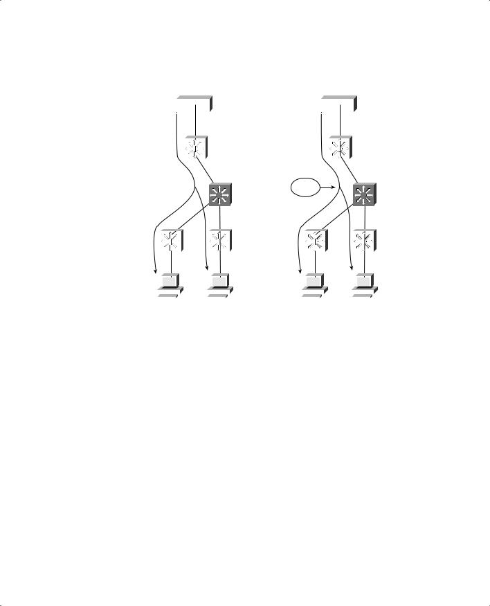
Figure 15-2 PIM Dense Mode Constructs a Multicast Tree
Multicast Server |
Multicast Server |
Root |
Root |
X
X
|
|
|
|
|
|
|
|
|
|
|
|
|
|
|
|
|
|
|
|
|
|
|
|
|
|
|
|
|
|
|
|
|
|
|
|
|
|
|
|
|
|
|
|
|
|
|
|
|
|
|
|
|
|
|
|
|
|
|
|
|
|
|
|
|
|
|
|
|
|
|
|
|
|
|
|
|
|
|
|
|
|
|
|
Recipient A |
Recipient B |
Recipient A |
Recipient B |
||||||||||||||||||||||||
|
|
Step 1: Flooding to Build the Tree |
|
|
|
|
|
Step 2: Pruning the Tree |
|||||||||||||||||||
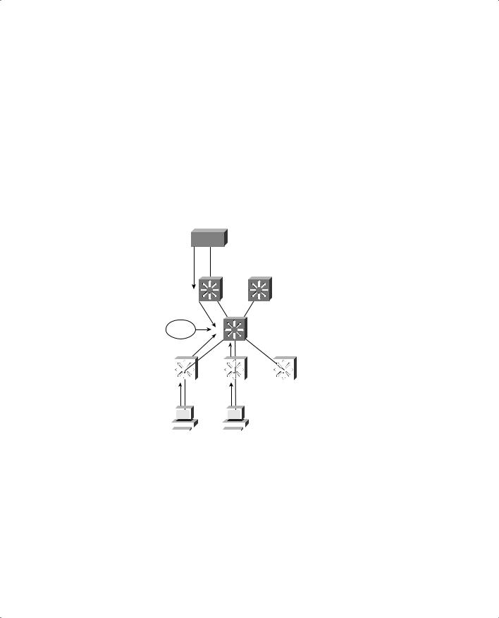
PIM Sparse Mode
PIM Sparse Mode (also called PIM-SM) takes a different approach—the multicast tree isn’t extended to a router unless a host there has already joined the group. The multicast tree is built by beginning with the group members at the end leaf nodes and extending back toward a central root point. The tree is built from the bottom up.
Sparse Mode also works on the idea of a shared tree structure, where the root is not necessarily the multicast source. Instead, the root is a PIM-SM router that is centrally located in the network. This root router is called the Rendezvous Point (RP).
The tree from the RP to the group members is actually a subset of the tree that could be drawn from the source to the group members. If a multicast source anywhere in the network can register for group membership with the RP, the tree can be completed. Because of this, the Sparse Mode tree is called a shared tree. Sparse Mode multicast flows are described as (*,G) because the tree allows any source to send to a group.