

МІНІСТЕРСТВО ОСВІТИ І НАУКИ УКРАЇНИ
Запорізький національний технічний університет
МЕТОДИЧНІ ВКАЗІВКИ
до лабораторних робіт з дисципліни
“Теорія електропривода”
для студентів спеціальності 8.092203
“Електропривод та автоматизація промислових
установок” для всіх форм навчання
2010
Методичні вказівки до лабораторних робіт з дисципліни “Теорія електроприводу” для студентів спеціальності 8.092203
“ Електропривод та автоматизація промислових установок” для всіх форм навчання. Укл.: В.І. Бондаренко, Ю.О.Крісан, Є.В.Васільєва – Запоріжжя: ЗНТУ, 2010. - 105 с.
Укладачі: В. І. Бондаренко, доц., к.т.н.
Ю.О.Крісан, доц., к.т.н.
Є.В.Васільєва, ст. викладач
Рецензент В. В. Кущ, доц., к.т.н.
Відповідальний
за випуск В. І. Бондаренко, доц., к.т.н
Затверджено
на засіданні кафедри ЕПА
Протокол № 3
від “ 16 ” грудня 2010
Content
Laboratory work №1.
Investigation of electromechanical and mechanical characteristics of direct current motor with independent excitation at different modes of braking and speed regulation
Laboratory work №2.
Investigation of electromechanical and mechanical characteristics of direct current motor with series excitation at different modes of braking and speed regulation
Laboratory work №3.
Investigation of electromechanical and mechanical characteristics of asynchronous motor with wound rotor at different modes of braking and speed regulation
Laboratory work № 4
Investigation of electric motor heating in long-term operation mode
Laboratory work №5.
Speed regulation and regulation circuit diagram of multispeed asynchronous electric motor
Laboratory work №6
Circuit diagram of electric drive reversing control when asynchronous motor with short-circuited winding is used
Laboratory work №7
Start and braking control of asynchronous motor with short circuited winding
Laboratory work № 8
Experimental investigation of transient in system generator-motor
List of references
Laboratory work №1
Investigation of electromechanical and mechanical characteristics of direct current motor with independent excitation at different modes of braking and speed regulation
The aim of laboratory work – is to study physical processes and features of direct current motor with independent excitation; investigate operation modes of motor and also ways of braking and speed regulation by analyzing of electromechanical and mechanical characteristics equations in different; experimentally investigate operation modes of motor and build its characteristics; perform analysis of experimental and calculated data.
1.1 General theory
Properties of direct current motor with independent excitation (DCM IE) are expressed by its mechanical and electromechanical characteristics. Electromechanical characteristic of DCM IE specifies relation of motor angular velocity ω to its current of armature circuit Ія, that’s why it is also called speed characteristics.
![]() (1.1)
(1.1)
where U – voltage of source, V; Се – construction coefficient, what includes construction features of motor and defines value of its EMF,
![]() ;
;
Ф – magnetic flux, Wb; Rя – total resistance what includes armature wining resistance Rя and additional resistance of external rheostat Rдод, Ohm; Ія – current of motor armature circuit, А.
Mechanical characteristic of DCM IE specifies relation of motor angular velocity to its rotating electromagnetic moment ω =f(M):
![]() (1.2)
(1.2)
where М – electromagnetic moment of motor, [Nm]; СМ – construction coefficient.
Analytic for mechanical characteristic of DCM IE could be specified from equation (1.1) by substitution Ія=М/СМФ, fined from (1.2). After substitution we will obtain:
 (1.3)
(1.3)
First component in equations (1.1) and (1.3) specifies speed of DCM IE ideal idling mode, [рад/с]. If we consider supply voltage and magnetic flux Ф being constant, idling speed in (1.1), (1.3) will be constant too. ω = U/CмФ = А. Suppose, that another component of equation (1.1) Rя and Ф are constant, then we take Rя / CмФ = В, and we will obtain new look of DCM IE electromagnetic characteristic equation .
![]() (1.4)
(1.4)
One can see that for conditions U=const, Ф=const, Rя=const quantities А and В are constant. We can state that equations (1.1) and (1.4) are graphically represented as straight line, what don’t cross center of coordinates.
For these conditions in equation (1.3) we specify Rя /С2 мФ2 = С and we’ll obtain
![]() (1.5)
(1.5)
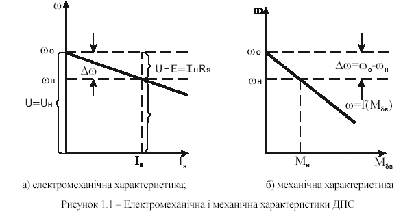
It’s easy to see that mechanical characteristic is graphically represented as the same straight line. Limitations U=const, Ф=const, Rя =const are caused by static idea about electric drive operation, that’s why electromechanical and mechanical characteristics of DCM IE are called static characteristics. Motor characteristics in case of nominal values of such parameters as U=Uном, Ф=Фном, Rя=Rяв are called natural static characteristics
![]()
Natural electromechanical(speed) characteristic (picture 1.1, а) – it is locus for what equation of motor armature electric balance is true
![]()
Static angular velocity drop on the motor shaft is effected by load action,
![]()
What is equal to (3…7)% from velocity of idling. That’s why natural characteristics of DCM IE are called hard. Constant coefficients В та С in equations (1.4) and (1.5) specify angle of inclination to horizontal axe of DCM IE characteristics and for absolute value С>В. Because of this reason angle of mechanical characteristics inclination (picture 1.1, б) in comparison with speed is more.
According to the principle of reversibility, DCM IE can operate in motor and generator mode. For generator mode equation of electric balance looks like this:
![]() ,
,
or
![]() .
.
Motor EMF becomes more than supply voltage and consequently armature current changes its direction. Hence, equation of speed characteristic will look like this:
![]() (1.6)
(1.6)
As Е>U, then we have conditions for sending (regeneration) energy in circuit. Substituting in (1.6) Iя = -M/CмФ , we obtain equation of mechanical characteristics for this mode
 (1.7)
(1.7)
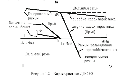
From the analysis of equation (1.7) one can see that motor moment M<0, that’s why it is braking moment. As the result of this, such mode of electric machine operation is called regenerative braking mode.
If we switch off the motor from supply voltage and add in armature circuit resistance RГ, keeping excitation constant, in this case electric machine will work in generator mode. After substitution in equation (1.1) U/CмФ=ω0=0, we’ll obtain equation for electromechanical characteristic:
![]()
where
![]() ;
;
RГ – braking resistance, Ohm.
So, machine operates in generator mode. After substitution in (1.3) U/CмФ=ω0=0) , equation of mechanical characteristic for this mode will look like:
As in this case М<0, this mode is called electrodynamic braking mode.
Characteristics of DCM IE, what were obtained by variation of parameters U, Ф, and Rя from their nominal values are called forced characteristics. Let’s add to armature circuit of motor what lifts big load considerable resistance Rдод . Increasing of resistance Rя=Rяв+Rдод turns motor from natural characteristic to forced one, what has greater inclination. In this case current and moment of motor are limited and velocity will be decreased. If the load is quite large direction of motor rotation can change. In this case, motor current and moment don’t change their sign, as motor was turned on to lift the load. But as load motion is slowed down, such operation mode of DCM IE is called plugging braking mode. In such conditions, motor EMF change sign and acts with supply voltage:
![]()
or
![]()
Speed and mechanical characteristics of DCM IE differ from expressions (1.1) and (1.3) only by presence of negative sign in angular velocity.
All contemplated DCM IE modes for one direction of rotation are shown on general diagram (picture 1.2).
1.2 Program of work
1.2.1 Study electric circuit diagram of laboratory set and features of its elements operation.
1.2.2 Take and build electromechanical characteristics of DC motor with shunt excitation:
– in motor mode ω=f(IЯ) – when U=Uн=220 V, Ф=Фн, Rдод=0;
– rheostat characteristics ω=f(IЯ) U=Uн=220 V and Rдод>0;
– mode of regeneration braking ω=f(IЯ) when U=Uн=220 V, Ф=Фн, Rдод=0;
–mode of plugging braking ω=f(IЯ) when U=Uн=220 V, Ф=Фн, Rдод>0;
–mode of dynamic braking ω=f(IЯ)when U=0, Ф=Фн,Rдод>0;
–case of motor supply voltage changing, when U=var, Rдод=0 and Ф=Фн;
–case of magnetic flux decreasing ω=f(IЯ)when Ф=var, Rдод=0 and U=U1=220V.
1.2.3 It is necessary to determine and build natural and forced characteristics.
1.2.4 According to the results of experimental research and calculations it is necessary to make short conclusion.
1.2.5 If Ф=Фн (Ів=Івн), Rдод=0, Мс=const=0 (Ія=const0) is necessary to take regulation characteristic of motor ω=f(U) in case of armature voltage variation from 20 to 220 V and build separately this characteristic. Using this static characteristic ω=f(U) coefficient of transmission К must be calculated (picture 1.3).
![]()
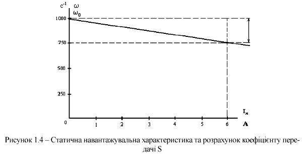
1.2.6 To take and build electromechanical (load characteristic) in motor mode ω=f(IЯ) when U=Uя=Uн=220 V, Ф=Фн (Ізб=Ізбн), Rдод=0, Мс=var (Ія=var) and by this static characteristic, transmission coefficient S must be calculated (picture 1.4).
![]()
1.2.7 According to the results of previous characteristics building and determinations of coefficients K and S, static model of DC motor with independent excitation in motor mode must be built (picture 1.5). This must be done according to above-listed material and methodical instructions of application 1Д.
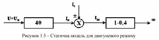
Rдод=0; Ф=Фн (Ізб=Ізбн)
Above-listed points 1.2.5, 1.2.6 and 1.2.7 are executed for any mode (according to teacher’s appointments), provided by curricular. This is about rheostat, regeneration braking, decreasing of magnetic flux and other characteristics.
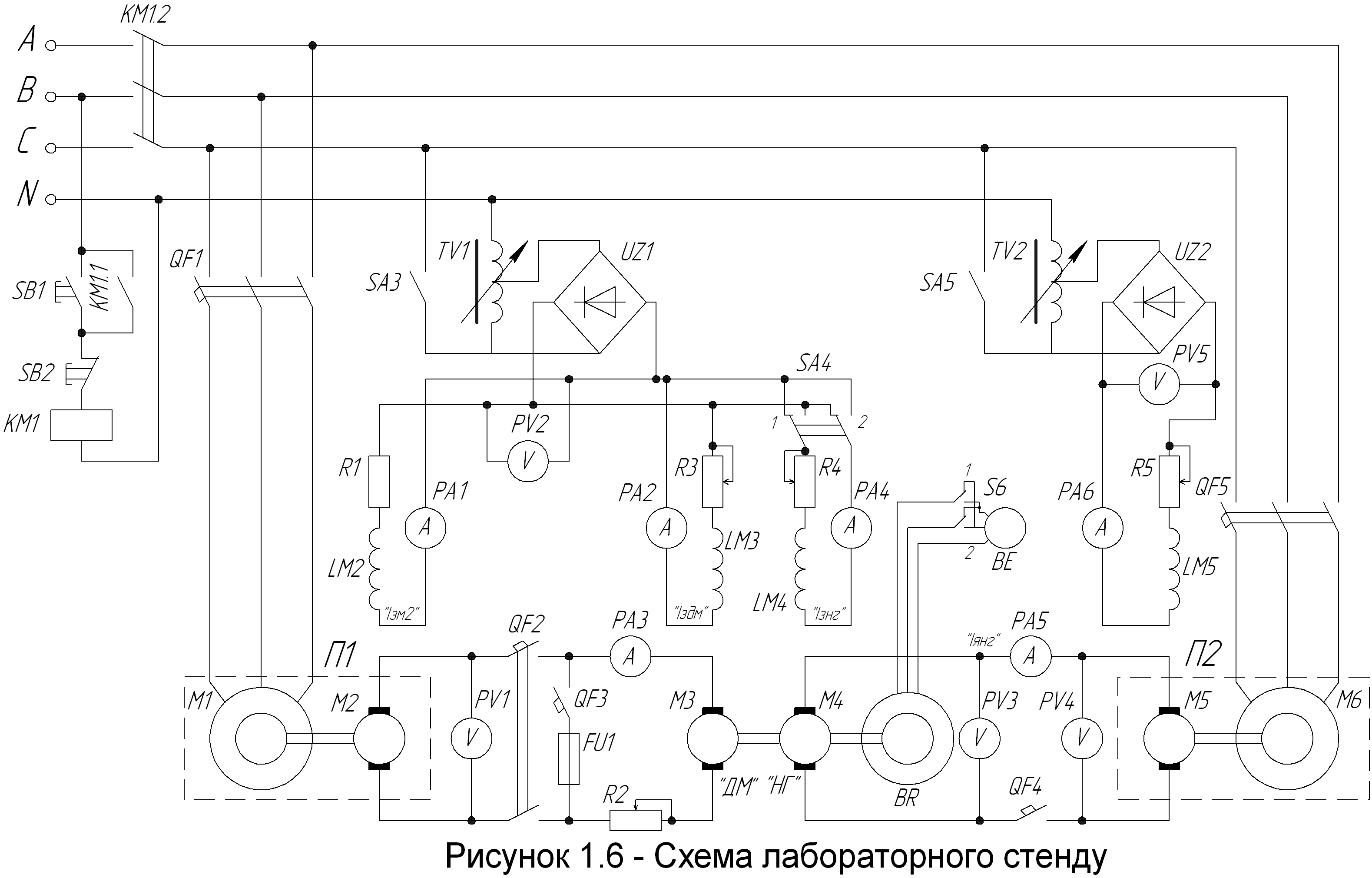
1.3 Description of laboratory installation
Circuit diagram of laboratory installation is shown on picture 1.3. Its main elements are: investigating DC motor (ДМ) and loading generator (НГ). They are marked on electric circuit scheme as М3 and М4 correspondently. НГ is dedicated for creation of regulating mechanic load on ДМ shaft, that is why they are connected with the same shaft. Speed of their consistent rotation is measured by tachometric device, what consists from tachometer generator ТГ and tachometer ТХ, marked on scheme as BR and BE.
Electric machine converters П1 та П2 are dedicated for power supplying of machines M3 and M4. Each of them consists from asynchronous motor and generator, what are connected with each other by the same shaft. Each of named machines convert AC supply energy into DC, what powers armature circuit of investigating and loading machine. Excitation of DCM originates from rectifiers UZ1, UZ2 by regulation of one-phase autotransformers ТV1 and ТV2 from AC side.
For accomplishing of all ДМ operation modes, what are listed in chapter 1.2 and for regulation of angular velocity regulation, commutation and electric measurement elements are located in circuit.
Regulation elements:
ТV1, ТV2 – laboratory autotransformers, what are used as regulators of DCM excitation voltage;
R1, R3, R4, R5 – variable resistances for current limitation and for regulation of DCM excitation;
R2 – variable resistance, what is used as start, regulating or braking rheostat, according to ДМ operation mode.
Commutation elements:
SB1, SB2 – buttons for energizing of laboratory installation and its turning off;
QF1, QF5 – switches, what are used for starting of asynchronous motors M1 and M6 and their protection from max current;
QF2 – switch, what is used for connection ДМ armature circuit to terminals of in case of all above-listed modes, except of dynamic braking mode;
QF3 – switch, what is used only in dynamic braking mode. In this case switch QF2 must be in off state;
QF4 – switch, what is dedicated for switching DCM M4 and M5 in parallel operation mode;
SА3, SА6 – switches for sending excitation to DCM;
SА4 – switch for changing the direction of magnetic flux in case of DCM braking in plugging mode;
SА5 – switch of changing the direction of tachometer rotation.
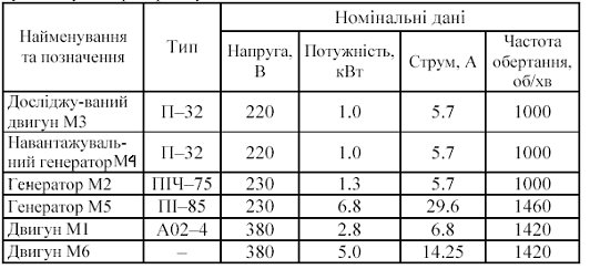
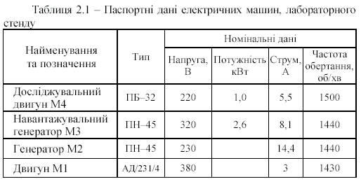
Electric measurement elements are dedicated for obtaining numerical information about experimental investigations (table1.1)
Table 1.1 – Passport data of electric machines, what are used in laboratory installation.
1.4 Preparation to work
Before the beginning of laboratory work student must:
– study theory and analyze the equations of electromechanical and mechanical characteristics if quantities Rдод, U, Ф are variated ;
–study the scheme of laboratory installation and order of laboratory work execution (look chapter 1.5), and also design report;
– get permission for laboratory work execution from the teacher, after passing necessary knowledge of this theme and safety rules testing; not prepared student is not allowed to laboratory work execution and works it off in established order.
1.5 Order of laboratory work execution
1.5.1 Before the beginning of work it is necessary to provide output conditions of scheme. All commutation elements must be turned off, but switches SА4 and SА5 must be in position “1”.
Set max resistance of rheostat R2 and min of R3, R1, R4, R5 must be set in average position. Hafts of autotransformers ТV1, ТV2 must be in “min” position.
After making sure in performation of these requirements, voltage must be send on laboratory set with a help of button “Вкл.” And by switching QF1 we start drive asynchronous motor of converter ПІ. After acceleration of generator M2, with a help of switch SA3 voltage must be send on autotransformer TV1 and with its help excitation circuits voltage of machines M2, M3, M4 must be risen up to 220 V. For control this process voltmeter PV2 is used.
In compulsory order it is necessary to make sure that switch QF3 is in on state. In this case QF2 must be switched on too, then investigated machine will start moving. Controlling is performed by voltmeter PV1, amperemeter PA3 and tachometer BE, what will show the voltage, current of armature circuit and angular velocity of ДМ. Next tusk is to set slowly min value of rheostat R2, after that make voltage of ДМ armature circuit reach 220 V. Rheostat R1 is used for this purpose. The mode we obtained is called real idling of ДМ. Draw attention on sign and value of current ІяДМ.
Then converter П2 is turned on. After that QF5 must be switched on and after acceleration of machines M5 and M6 what are connected with the same shaft one must energize autotransformer TV2 by switching on SA6. Using the haft of autotransformer TV2 it is necessary to make voltages of machines M4 and M5 armature circuits be equal. QF4 is switched on only after fixing balance of voltages. Both machines will be turned on parallel operation. In such a way laboratory installation is ready to work.
1.5.2 Motor mode of ДМ operation is provided in such a way. Turning slowly haft of the rheostat R5 to “max” position and with a help of rheostat R1 set voltage of ДМ circuit equal to 220V. Current of armature circuit will be equal to:
IЯДМ=+(1-2,5) А.
Controlling is provided by meters PV1 and PA3. With a help of tachometer angular velocity of ДМ must be checked and all data of measurements in motor mode must be written down in table 1.2. (Draw attention on operation mode of investigating and loading machines: ДМ is motor, НГ is generator)
1.5.3 Ideal idling mode, is not possible to achieve in real conditions, because of losses(for instance-to overcome friction in bearings). But it can be achieved with a help of additional mechanical energy, what delivers on ДМ shaft. It’s source in laboratory installation is machine M4, what must work in motor mode. In this case it in necessary to increase aggregate speed, what consists from machines M5 and M6. Therefore haft of rheostat R5 is moved to “min” position. Current of ДМ armature circuit is decreased till the value IЯДМ=+(1-2,5) А, but the voltage in this moment can be over 220V (watch the meters РА3 та РА1).
Then rheostat must be turning to max resistance until voltage will be equal to 220V. In the same time current of investigating machine will tend to zero. Data of measurements, when ІяДМ=0 must be written down in the table 1.2. Draw attention on loading generator operation mode: with increasing of М5-М6 aggregate speed it is changed to motor.
1.5.4 Further energy delivering from the П2 will turn ДМ in generator mode, and current ІяДМ will change its direction: ІяДМ<0. Keep moving haft of rheostat R5 to “min” position until current of ДМ armature will be equal ІяДМ=-(1-2.5) А. Then voltage of ДМ armature circuit must be set on the value 220V by turning haft of rheostat R1 to “max” position. Measurement data must be written down in the table 1.2. In this case investigating machine-is generator, loading generator-is motor.
1.5.5 For getting rheostat characteristics it is necessary to switch ДМ from generator to motor mode: haft of rheostat move in “maх” position. After that set min resistance of rheostat R1 and switch on the first section of rheostat R2 (30 Ohm). Voltage of ДМ armature circuit will be much more than nominal value. It must be decreased to 220V by setting rheostat R4 in position “Виведений”, and then turn haft of autotransformer TV2 to “min” position. Current of ДМ armature circuit will be equal to ІяДМ+3 А.
Table 1.2 – Experimental and calculated data for building electromechanical and mechanical characteristics of DCM with shunt excitation.
Mode of ДМ operation |
Experiment |
calculation |
||||||
U, B |
IяДМ |
IзДМ |
R2, Ом |
n, rev/min |
ω, rad/s |
M, Nm |
||
А |
||||||||
Motor |
220 |
|
0,6 |
0 |
|
|
|
|
Ideal idling |
220 |
0 |
0,6 |
0 |
|
|
|
|
Generator |
220 |
- |
0,6 |
0 |
|
|
|
|
Rheostat characteristic 1 |
220 |
|
0,6 |
60 |
|
|
|
|
Rheostat characteristic 2 |
220 |
|
0,6 |
30 |
|
|
|
|
Plugging braking |
220 |
|
0,6 |
60 |
|
|
|
|
Dynamic braking |
220 |
- |
0,6 |
60 |
|
|
|
|
220 |
- |
0,6 |
30 |
|
|
|
||
Forced characteristics when U=Var |
180 |
|
0,6 |
0 |
|
|
|
|
180 |
|
0,6 |
0 |
|
|
|
||
160 |
|
0,6 |
0 |
|
|
|
||
160 |
|
0,6 |
0 |
|
|
|
||
Forced characteristics when Ф=Vаr |
220 |
0 |
0,5 |
0 |
|
|
|
|
220 |
|
0,5 |
0 |
|
|
|
||
220 |
0 |
0,4 |
0 |
|
|
|
||
220 |
|
0,4 |
0 |
|
|
|
||
Measurement data must be written down in table 1.2. After that one more section of rheostat R2 must be switched on. As in this case voltage of ДМ armature circuit will differ from nominal, it must be set equal to 220V by вводячи rheostat R1. Measurement data must be written down in table 1.2. Now investigating machine-is motor and loading generator-is generator.
1.5.6 Before turning ДМ in plugging braking mode it is necessary to ensure that both sections of rheostat R2 in armature circuit are switched on (60 Ohm) and voltage of ДМ and НГ armature circuits are not over 100V(watch voltmeters PV1 and PV3). This is provided by moving haft of rheostat R1 in position “Введений”. Only after that one can switch SA5 and SA4 in position “І І”. Then set min resistance of rheostat R1 and all measurement data must be written down in the table 1.2. Special feature of this method is the fact that investigated machine windings are switched on previous direction of rotation, but its armature rotates in opposite direction making braking moment, because of active moment action, what is created by aggregate П2. Plugging braking mode of ДМ arises through changing of current direction in excitation circuit of machine M4.
1.5.7 In dynamic braking mode armature circuit of ДМ is switched off from power source (look at picture 1.3) and is shunted by resistance R2. As ДМ is rotated with a help of aggregate П2 it works in generator mode. For switching in dynamic braking mode it is necessary to set max resistance of rheostat R1 and switch off QF2. Then, switches SA4 and SA5 must be rotated to position “І” and switch QF3 must be closed; moving haft of rheostat R1 to position “Виведений”, rise ДМ voltage up to 220 V. Rotating haft of autotransformer TV2 to “maх” position value ІяДМ=-(1-2.5)А must be set and data of measurements written down in table 1.2. Switch off one of rheostat R2 sections and repeat measurements when R2=30 Ohm.
1.5.8 Characteristics of motor mode when supply voltage is decreased U<220V demand taking two values of ДМ angular velocity: when ІяДМ =0 and ІяДМ=(1…5)А. For this reason ДМ must be switched from dynamic braking mode to motor mode. It is necessary to set max resistance of rheostat R1, then open switch QF3 and close QF2. Then, move haft of rheostat R1 to “min” position, until U1=220 V, and set min resistance of rheostat R2. Voltmeter PV1 and amperemeter PА3 must register values U220 V, а ІяДМ(1-2)А. Moving haft of rheostat R1 in position “Введений”, one must ensure that current ІяДМ tends to zero when U=180 V. When current ІяДМ will reach zero results of measurements must be written down in table 1.2. For taking another value of angular velocity ДМ must be loaded, and U=180V. For this purpose with a help of autotransformer TV2 it is necessary to decrease voltage to value U=180V and also move haft of rheostat R1 to position “Виведений” until U=180 V. In this moment ІяДМ=(1…3)А. Measurement results must be written down in table 1.2. For taking another forced electromechanical characteristic when U=var it is necessary to perform similar operations. Set max resistance of rheostat R1, and in his moment U=160 V, ІяДМ=0. Write down the data in table 1.2. Then, with a help of autotransformer TV2 voltage of armature circuit must be sharply decreased to value U=140 V, and after that, moving haft of rheostat R1 to “min” position, restore its value to U=160 V. In this moment ІяДМ=(1…3)А. Results must be written down in table 1.2.
1.5.9 For taking ДМ characteristics when Ф=var first of all with a help of autotransformer TV2 is necessary to restore supply voltage to the value U=220V, then limit current of ДМ excitation to some value in this range(0,4…0,5) A (watch amperemeter PA2) and provide ІяДМ=0. Results of measurements must be written down in table 1.2. Move haft of rheostat R1 to “min” position, until U=220 V, and ІяДМ=2 А, after that with a help of autotransformer set U=220V and ІяДМ=(1…3)А. Results of measurements must be written down in table 1.2.
1.5.10 Building all electromechanical characteristics, except of characteristics when U=var and Ф=var must be done on one graph. (Necessary information is given on the picture 1.2, and results of experimental investigations are in table 1.2). Before their building also is necessary to convert frequency of rotation what was taken by tachometer(rev/min) in angular velocity (rad/s):
![]() .
(1.8)
.
(1.8)
Regulated electromechanical characteristics for conditions U=var and Ф=var must be built together with natural characteristics on another graph. Student must know form of these characteristics by the results of equations (1.1) and (1.5) self-analyzing, when parameters U and Ф are variated. In such a way, for building of electromechanical characteristics is enough to have results of experimental measurement, shown in table 1.2. Final result of work is building of mechanical characteristic.
ω=f(М) (except of characteristics, when ДМ magnetic flux is damped). Hence, transfer from values {n; IяДМ } to parameters {ω,M} is necessary. For this purpose one must use equations (1.8), (1.2), (1.1) to determine angular velosity and then from (1.1) get values for nominal parameters.
![]() ,
,
After that
![]()
Internal resistance of motor armature circuit could be fined approximately:
![]() ,
,
Where efficiency of motor:
![]()
1.6 Content of report
Report to laboratory work must contain:
– tables with passport data of electric machines, results of measurements and calculations and also electric circuit diagram of laboratory installation;
– graphs of electromechanical and mechanical characteristics of DCM IE;
– short conclusions about features of studied DCM IE operation modes, calculations and analysis of obtained graphical material;
– static model, shown by regulating and loading characteristics with coefficients K and S calculation;
– static model of motor with written value of transmission coefficients and conditions under what model was built.
1.7 Control questions
1.7.1 State operation of laboratory installation in general and explain purpose of its elements.
1.7.2 In correspondence to electric circuit diagram state sense of each operation mode of DCM IE.
1.7.3 Tell conditions of taking correspondent characteristics of DCM IE.
1.7.4 What is the difference and relation of electromechanical and mechanical characteristics.
1.7.5 How to build DCM IE nature mechanical characteristic by passport data.
1.7.6 What is the difference between natural and forced characteristics.
1.7.7 Compare the ways of DCM IE speed regulation.
1.7.8 Compare the braking modes, what were studied in laboratory work.
1.7.9 What is the difference between real and ideal idling of DCM IE. 1.7.10 Explain the linearity of DCM IE static characteristics.
1.7.11 How to determine hardness of any DCM IE characteristic. Name the industry brunches where DCM IE is used.
1.7.13 What characteristics are called static.
1.7.14 What characteristics are called regulating
1.7.15 What characteristics are called loading
1.7.16 For what purpose static characteristics are built.
1.7.17 For what purpose static models of motors, operating machines and operating processes are built.
1.7.18 How does voltage transmission coefficient K is calculated
1.7.19 How does static coefficient(S) is calculated.
1.7.20 Tell in what a way nonlinear characteristics of DCM IE are linearized 1;2;3].
Laboratory work №2
Investigation of electromechanical and mechanical characteristics of direct current motor with series excitation in different modes of operation, speed regulation and braking
The aim of laboratory work – is to study physical processes and properties of direct current motor with series excitation by taking electromechanical characteristics, calculation of mechanical characteristics and also by analysis of these characteristics in motor and braking modes.
2.1 General theory
For direct current motor with series excitation (DCM SE) general look of electromechanical characteristic equation, what specifies relation between angular velocity ω and armature circuit current Ія , is the same as for direct current motor with independent excitation (DCM IE):
![]() (2.1)
(2.1)
where U – voltage of motor power supply, V; Ія – current of motor armature circuit, А; Rяк – total armature circuit resistance, what includes resistance of armature winding Rяв, resistance of excitation winding Rз and resistance of external rheostat Rр, Ohm; См –is constant coefficient what allows for motor construction features; Ф –magnetic flux, Wb; ω-motor angular velocity, s-1 .
Unlike DCM IE, in this motor magnetic flux Ф is a function of current Ія , what is graphically represented by magnetizing curve of motor steel and has non-linear form. In such conditions definite analytical expression is absent for electromechanical and mechanical characteristics of DCM SE:
ω=f(IЯ), ω=f(M),
where М – is moment of motor shaft, Nm, what is specified by relation
![]() .
.
If for analysis simplification we neglect magnetic system saturation and assume that relationship between flux and armature current is direct (consider that ФIЯ), the moment of motor is:
![]() (2.2)
(2.2)
In this case from equation (2.1) by substitution of current values (2.2) we’ll obtain expression of mechanical characteristic:
![]() (2.3)
(2.3)
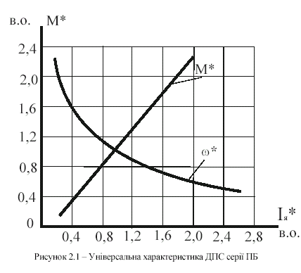
Hence, when magnetic circuit is saturated, magnetic characteristic is drawn as a curve. Y-axis is asymptote for it. Equation (2.3) gives only general idea about mechanical characteristic of DCM SE. For more exact calculations is impossible to use this equation, because in modern practice there is almost no machines with not saturated magnetic system. Mechanical characteristic, obtained for normal switching scheme, when parameters of voltage supply are nominal and without additional resistances is called natural. Its building for DCM SE is performed at selected scale, using catalogue data what provide general natural characteristics in relative units.
On picture 2.1 is shown approximated general characteristic of DCM SE. Regulation of DCM SE velosity is performed either by changing of supply voltage U, or regulating resistance of armature circuit rheostat Rе. And using rheostats what shunt armature winding is possible to regulate excitation current Із and velocity.
On picture 2.2 is shown scheme of DCM SE switching with rheostats Rшя and Rшз, what provide taking forced characteristics of motor.
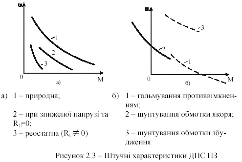
On picture 2.3 is shown approximate look of DCM SE mechanical characteristics. Analogous look have electromechanical characteristics.
DCM SE does not have end value of idling speed at all modes, except of armature circuit shunting. Because, when we decrease loading moment on the shaft and decrease current of armature circuit Ія, magnetic flux Ф damps greater then angular velocity ω increases. That’s why motor EMF E=СмФω can’t be over the value of supply voltage U and motor can’t be turned in generator mode and send energy in circuit (look at curve 1 on the picture 2.3, a)
Angular velocity of motor shaft rotation sharply increases in case of law loadings because of sufficient non-linearity of DCM SE mechanical and electromechanical characteristics. That’s why it is prohibitive to operate drive in this mode.

When DCM SE armature winding is shunted by rheostat Rшя (look at picture 2.2) current decreases to zero value (end value of EMF) and excitation winding is powered by current, passing through shunt rheostat.
This provides crossing mechanical characteristic of this mode and Y-axis(characteristic 2 on picture 2.3, б). DCM SE operates in generator mode with shunt rheostat.
For DCM SE two braking modes are possible: plugging and dynamic. Under the action of braking moment in plugging mode motor shaft rotates in opposite direction to that one, what corresponds to supply voltage polarity (curve 1 on picture 2.3, б)
In dynamic braking mode armature winding is short-circuited with external rheostat. In this situation occur conversion of drive mechanical energy into electrical, what is lost in external rheostat. So, DCM SE operates in generator mode. DCM SE are used in electric drives, where in case of small load, speed rising is prohibitive. Because of little hardness of mechanical and electromechanical characteristics.
Shunting of DCM SE armature circuit winding is used, when it is necessary to provide stable motor operation under low load moment.
2.2 Program of work
2.2.1 Study electric circuit diagram of laboratory installation and its elements operation features.
2.2.2 Take electromechanical characteristics of DCM SE in motor mode at different values of armature circuit rheostat resistance.
2.2.3 Take electromechanical characteristics in plugging mode.
2.2.4 Take electromechanical characteristics in case of armature winding shunting.
2.2.5 Take electromechanical characteristics in case of excitation winding shunting.
2.2.6 Using the results of DCM SE electromechanical characteristics building it is necessary to determine and build its natural and forced mechanical characteristics.
2.2.7 Make short conclusions about the results of investigations.
2.2.8 Set motor mode, when armature circuit rheostat resistance is max and changing armature voltage take static regulating characteristic. Perform linearization of regulation characteristic and calculate transmission coefficient “K”. Value of rheostat resistance and range of armature circuit voltage measurement is set by teacher.
2.2.9 Using taken mechanical characteristic of DCM SE in motor mode, when armature circuit rheostat resistance and voltage are the same it is necessary to build loading characteristic, perform its linearization and calculate transmission coefficient “S”. Values of rheostat resistances must be the same as in section 2.2.8
2.2.10 Using the results of coefficients K and S calculation build static model of direct current motor with series excitation.
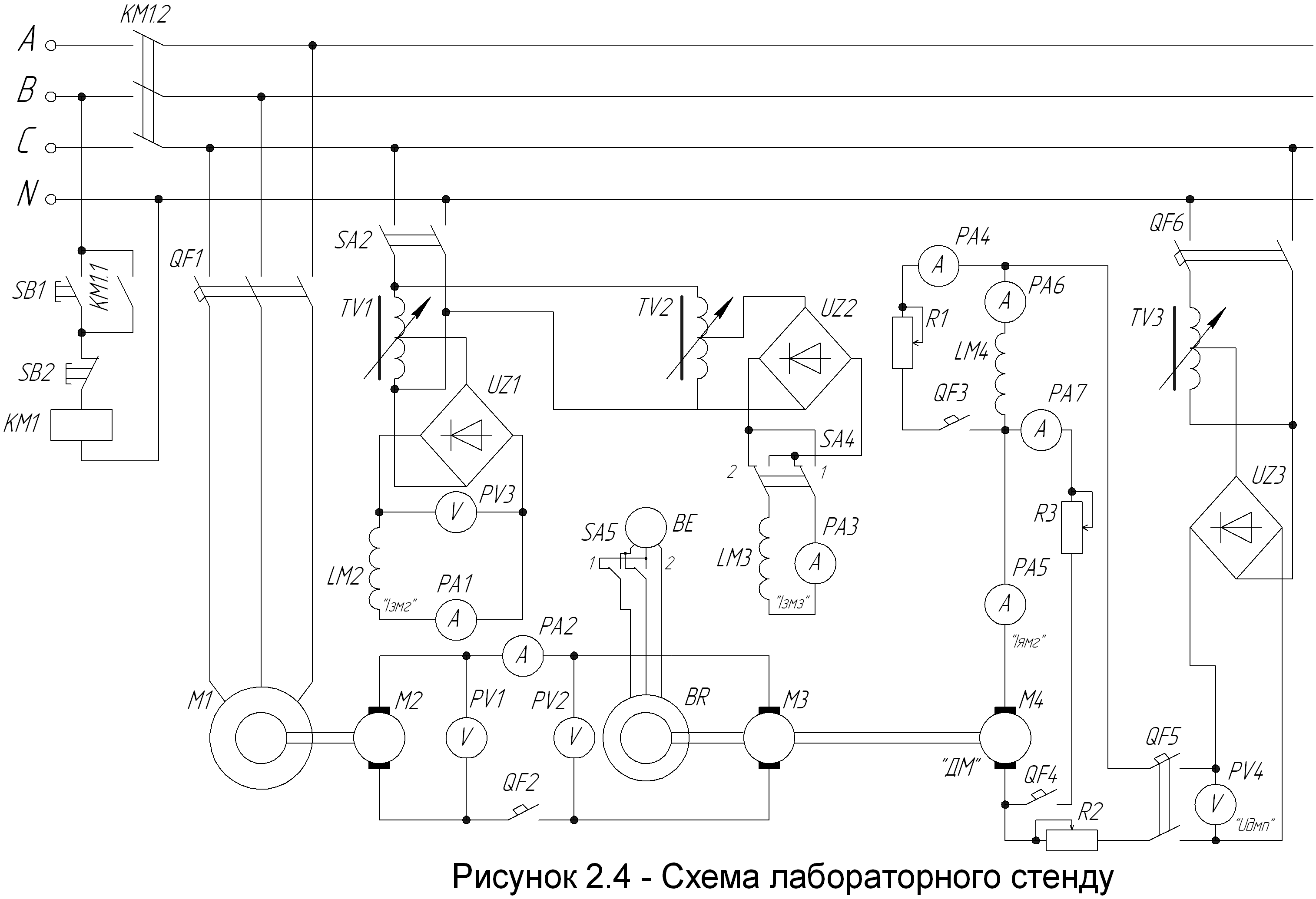
2.3 Description of laboratory installation
Electric circuit diagram is shown on the picture 2.4. Investigating machine (ДМ) is direct current motor with series excitation, passport data is in the table 2.1. ДМ armature circuit resistance R2 is used as staring, regulating or braking. It depends on operation mode. Loaded generator M3 is located on the same shaft with ДМ and it is intended for creation of regulating load on the shaft of ДМ. Electro machine converter П operates as load or power source of M3 (it depends on operation mode). This converter consists from drive asynchronous motor with short-circuited winding(M1) and direct current generator with independent excitation(M2). Passport data of these machines is also shown in the table 2.1.
For ДМ power supply one-faze autotransformer TV3 and rectifier UZ3 are used. Switch QF4 is dedicated for armature winding shunting, QF3 –for shunting of ДМ excitation winding, QF2 – for switching armature circuits of M2 and M3 on parallel operation. Excitation windings of machines M2, M3 are powered from rectifiers UZ2 and UZ3, what are switched to alternating current circuit via autotransformers TV2 and TV3 correspondently. Regulation of load moment on ДМ shaft in motor mode is performed by regulation of machines M2, M3 armature circuit current. For this purpose voltage variation on the terminals of generator M2 is necessary. For turning ДМ in plugging braking mode, polarity of M3 excitation current is changed and M3 starts operation in motor mode. In order to measure frequency of rotation, tachometric device is used. It consists from sensor (3-faze asynchronous tachometer generator BR, located on the one shaft with ДМ) and receiver BE what is mounted on the one shaft with ДМ too. Switch SA4 is used for changing the direction of generator M3 magnetic flux. Because of sharp ДМ speed rising, when there is low load on the shaft, one must watch velocity in order to prevent it from being more than in 1.25 times over nominal(2000 rev/min) .
2.4 Preparation to laboratory work
Every student must be ready to the next laboratory work in time. For this purpose it is necessary to study theoretical course and all demanded questions, order of laboratory work execution and write the titles of report.
Before the beginning of laboratory work execution student shows teacher his report and answers on the questions about this laboratory work. Unprepared student is not allowed to execute laboratory work and works it off in established order.
2.5 Order of laboratory work execution
2.5.1 Before the beginning of laboratory work it is necessary to check initial states of installation elements: switch SA5 and tumbler SA4 must be in position “І”, other switches must be in off state. Hafts of autotransformers TV1 and TV2 must be in left position(“min”), starting rheostat R2-in “min” position, haft of autotransformer TV3-in position “min”.
2.5.2 Switching of scheme is performed in such a way. For test bench powering is necessary to press the button “Вкл”. ДМ starting must be done with low voltage, starting from zero. For this purpose, when QF3 is in off state, it is necessary to switch on QF6. Assured that UДМ=0 (watch voltmeter PV4) one must switch on QF5. With a help of TV3 smoothly increase voltage UДМ until motor frequency of revolutions will reach 900…1000 rev/min. Using QF1 start converter П. Switch on SA3 and, rotating haft of autotransformer TV1, is necessary to rise excitation voltage Uз to 100V (watch voltmeter PV3). With a help of autotransformer TV2 set voltage of loading generator U2=160 V (watch voltmeter PV2) and using autotransformer TV1-set voltage of generator M2 U1=160 V. “І” position of switch SA4 matches machines M2, M3 polarities, that’s why when U1=U2 is necessary to switch them on parallel operation using QF2. After QF2 switching scheme is completely ready to work.
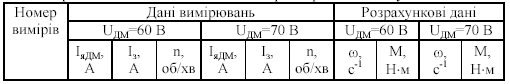
2.5.3 DCM SE characteristics in motor mode, when Rд=R2 are changed in such a way. With a help of TV3 set voltage UДМ=60 V. Changing by autotransformer TV1 load moment of ДМ by variation of machine M3 voltage, what operates in generator mode, is necessary to take instrumentation indications: current ІяДМ (watch amperemeter PA5) must be not over 7 A. Measurements are performed with step what is approximately equal to 1 A. Measurement data and results of further calculations must be written down in table 2.2.
Repeat experiment, when voltage UДМ=70 V.
Table
2.2 – Measurement
data and results of calculation for obtaining motor electromechanical
and mechanical characteristics.
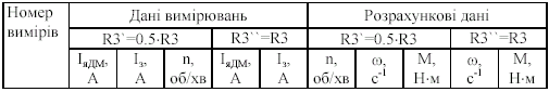
2.5.4 Investigation of DCM SE characteristics in motor mode, when Rд≠0, is performed almost in the same way as in previous experiment. Voltage UДМ=70 V, but in ДМ armature circuit is necessary to add rheostat R2. Experiment is done twice: first time- when R2`=0,5*R2, second- when R2``=R2. Measurement is performed with step, what is approximately equal to 0,5 А.
Measurement data and results of further calculations must be written down in table 2.3.
Table
2.3 – Measurement
data and results of calculation for determination of
electromechanical and rheostat mechanical characteristics in motor
mode, when Rд≠0
and in plugging braking mode.

2.5.5 Plugging braking mode is continuation of previous mode, but with greater value of R2. For switching ДМ in this mode is necessary to switch M3 in motor mode and then M3, what gets power from generator M2, will rotate ДМ in opposite direction to ДМ moment. In such a way, M3 will create active opposition moment.
For ДМ switching in plugging braking mode is necessary to perform next steps:
– in correspondence to the scheme of previous experiment, when UДМ=70V, rheostat R2 resistance is max and ДМ velocity is close to zero, one must reduce excitation current ІЗМ2 of machine M2 to zero value;
– turn SA4 in position “П”;
– with a help of TV1 rise current ІЗМ2 , and after that, system ДМ – М3 reversing will happen.;
– switch SA5 on control panel, because the direction of tachometer generator(BE) rotation will be changed;
– using TV1 regulate voltage of generator M2 and moment of it, perform 3-4 measurements, after that return scheme to initial position. For this purpose with a help of TV1 decrease current ІЗМ2 to zero and switch SA4 in position ”І”. Measurement and further calculations results write down in table 2.3.
2.5.6 For investigation of DCM SE characteristics in motor mode, when armature winding is shunted is necessary to perform next steps:
– set UДМ=70 V;
– set max resistance of rheostat R2 and rheostat R3, what shunts armature winding;
– switch on QF4;
– changing ДМ load by generator M2 voltage variation(use autotransformer TV1), perform 5-6 measurements. Measurement data and results of calculation write down in table 2.4.
Repeat experiment, when R3 resistance was changed in two times. This experiment gives the opportunity to get end value of idling speed, and equation ІяДМ=0 is correspondent to it. In case of further load redusing, current ІяДМ changes its sign.
Table
2.4 – Measurement
data
and
the
results
of
calculations
for
electromechanical
and
mechanical
characteristics
determination,
when
armature
winding
is
shunted
2.5.7 Investigation of DCM SE in motor mode, in case of excitation winding shunting is performed in such a way:
– set scheme initial condition UДМ=70 V;
– switch off QF4;
– set minimum value of R2;
– set min resistance of rheostat R1;
– switch on QF3;
– as in previous case, changing of ДМ load is performed by generator M2 voltage variation(use autotransformer TV1), then is necessary to take 5-6 measurements and write down in the table 2.5 the results of measurements and further calculations; repeat experiment, when R1 was reduced in two times. During the experimentation is important to watch frequency, because it must be not over than 2000 rev/min.
Table
2.5 – Measurement
data
and
the
results
of
calculations
for
electromechanical
and
mechanical
characteristics
determination,
when
excitation
winding
is
shunted.
2.5.8 For building and determination of characteristics these guidelines are necessary. As electromechanical characteristics are relations ω=f(IЯ), their building could be done directly by measurement data. Also one must convert taken by tachometer frequency of revolutions (n, rev/min) in angular velocity, s-1(in system СІ):
![]() .
(1.8)
.
(1.8)
Natural mechanical characteristic of DCM SE ω=f(М) is built using general characteristics ω*=f(I*), М*=φ(I*), shown on the picture 2.1. For this purpose using graph, shown on the picture 2.1, determine correspondent values for several (6-7) values of І*:
ω*= ω /ωн , М *= М/Мн
After that, calculate absolute values ω = ωн ω*, М =Мн М* taking in account, that
Мн = Рн/ ωн
where ωн, Рн – motor passport data.
Forced mechanical characteristics must be built using correlation:
![]() (2.5)
(2.5)
where Мш – requested value of forced moment; М – motor moment at present R1; Із– current of DCM SE excitation winding.
Order of forced mechanical characteristics calculation and building:
– for preselected and experimentally taken K point of electromechanical characteristic, using graph of natural characteristic М=(I) (look at picture 2.1) is necessary to find value of moment, what motor could have, if the current was equal to current, in other words, at current Із, what pass via DCM SE excitation winding, when velocity is ωк and switching scheme is the same;
– then by formula (2.5) determine Мш, using as Ія quantities indications of amperemeter PA5, and as Із quantities indications of amperemeter PA6, what are correspondent to selected point ωк ;
– repeat listed operations for all experiments, build forced characteristics ω=f(Мш)
2.6 Content of report
Laboratory work report must contain:
– tables with passport data of electrical machines, measurement data and results of calculations;
– graphs of general characteristics of DCM SE;
– graphs of electromechanical characteristics;
– graphs of natural and forced characteristics;
– short conclusion with motor characteristics analysis;
– linearize static regulting and loading characteristics of DCM SE;
– static model of DCM SE, what satisfies conditions, listed in sections 2.2.8 and 2.2.9.
Note. Guidelines of static model building are in application 1Д.
In order to avoid heaping of curves on the graph, it is necessary to build mechanical characteristics separately from electromechanical. Curves for modes listed in section 2.5.3-2.5.4 must be on one picture, curves for modes 2.5.5-2.5.7-on another.
2.7 Control questions
2.7.1 State laboratory installation operation in general and features of its separate elements.
2.7.2 In correspondence to electric circuit diagram, state every investigated mode of DCM SE.
2.7.3 Sate main idea of mechanical and electromechanical characteristics, their correlation and difference.
2.7.4 How to build natural and mechanical characteristic of DCM SE using general characteristics ω=f(IЯ), М=(IЯ).
2.7.5 Поясніть не лінійність характеристик ДПС ПЗ.
2.7.6 Does it possible to regenerate energy in plugging braking mode of DCM.
2.7.7 Does it possible to obtain end value of DCM SE idling speed.
2.7.8 Pros and cons of DCM SE in comparison with DCM IE.
2.7.9 Name the industry brunches, where DCM SE is used.
2.7.10 How does static regulating characteristic of DCM SE look
2.7.11 How does static loading characteristic of DCM SE look 2.7.12 In what a way static loading characteristic is linerized
2.7.13 How does static characteristic look at different values of load.
2.7.14 Draw approximate look of static linearized regulating and loading characteristics at different operation modes of DCM SE(motor, plugging, shunting of armature winding, shunting of excitation winding) [2,4,5].
ЛАБОРАТОРНА РОБОТА №3
Дослідження електромеханічних та механічних характеристик асинхронного двигуна з фазним ротором у режимах роботи при різних способах регулювання швидкості двигуна, та режимах гальмування
Мета роботи – вивчити фізичні процеси та властивості асинхронного двигуна з фазним ротором шляхом зняття електромеханічних характеристик, розрахунку та побудови механічних характеристик, а також аналізу цих характеристик у генераторному, двигуневому та гальмівному режимах.
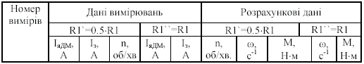
Через те, що електроустаткування стенду лабораторної роботи №3 не містить перетворювача частоти з певним законом регулювання, то не є можливим зняти реальну регулювну характеристику АД з фазним ротором. Тому при побудові моделі необхідно прийняти лінійний характер залежності швидкості від напруги при fс=const=50 Гц (fс – частота мережі живлення двигуна), тобто у першому наближенні може бути прийнятий пропорційний закон частотного регулювання (рисунок 3.3).
Точка лінеаризації повинна відповідати параметрам електромеханічної характеристики у двигуневому режимі.
Точка лінеаризації (тобто значення напруги, яка подається на статор двигуна) задається викладачем.
За характеристикою рисунку 3.3 обчислюється коефіцієнт передачі “К” для побудови статичної моделі двигуна.
3.1 Основні теоретичні положення
На відміну від конструкції двигунів постійного струму та синхронних, асинхронний двигун є індукційним, тобто зв’язок між статором і ротором електромагнітний, а це значить, що неможливо для формування аналітичного виразу механічної характеристики безпосередньо користуватися методом теорії електричних кіл.
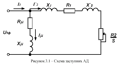
Тому основний метод аналізу процесів у асинхронних двигунах –використання еквівалентних схем заступних, у яких електромагнітні зв’язки замінені електричними (коло статора електрично пов’язано з колом ротора). Через симетрію трифазного асинхронного двигуна, розглядаються фізичні явища, відповідно тільки до однієї фази двигуна (обмотки статора і ротора з’єднані “зіркою”). Найбільш зручна для цього спрощена Г-подібна схема заступних (рисунок 3.1) з намагнічуючим контуром, винесеним на затискачі. Де U1ф – первинна фазна напруга; І1 – фазний струм статора; І`2 – зведений струм ротора; І - струм намагнічування; Х1, Х`2 – індуктивні опори розсіювання первинної та зведеної вторинної обмоток; R, Х- активний та індуктивний опори намагнічуючого контуру; R1, R`2 – активні опори первинної та зведеної вторинної обмоток;
![]() -
ковзання
-
ковзання
Виведення рівняння механічної характеристики виконується з умов рівності втрат у роторі для реального двигуна і для заступної схеми:
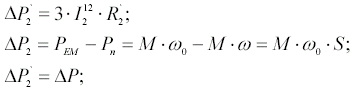
![]() (3.1)
(3.1)
де Р`2 – втрати у роторі для заступної схеми; Р2 – втрати у роторі для реального двигуна; РЕМ – електромагнітна потужність; Рn – корисна потужність (потужність на валу двигуна); ω0 – синхронна швидкість (швидкість ідеального неробочого ходу машини); ω - швидкість ротора двигуна.
Із заступної схеми (рисунок 3.1):
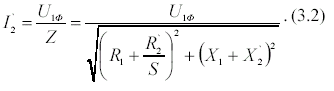
Вирішуючи спільно (3.1) та (3.2), отримуємо вираз для механічної характеристики асинхронного двигуна:

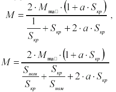
За рівнянням (3.3) можна побудувати механічну характеристику, якщо відомі опори кола статора і ротора. Ці величини задані у паспорті машини і, тому для практичних розрахунків формула (3.3) незручна. Для цієї мети більш зручним є рівняння (3.4), отримане після дослідження виразу на екстремум й спрощення рівняння (3.3):
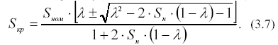
де Мmax – максимальне значення моменту у двигуневому режимі, що відповідає критичному значенню ковзання (Sкр), визначається з перевантажувальної здатності =Mmax/Mном, вказаної в у каталозі; а=R1/R’2.
Для звичайних асинхронних двигунів параметр а близький до одиниці, тому для звичайних інженерних розрахунків можна користуватися більш спрощеною формулою, отриманою з виразу (3.4):
Якщо у рівнянні (3.4) покласти R1=0, яке мале порівняно з величиною X2 +X21
(особливо для великих асинхронних машин), то рівняння механічної характеристики набуде ще більш спрощеного вигляду:
Вираз (3.6) з достатньою для практики точністю відповідає фізичним процесам у двигунах. Побудовану на його основі характеристику можна поділити на дві ділянки – лінійну та нелінійну.
На рисунку 3.2 показані ці ділянки механічної характеристики у координатах М=f(S) (рисунок 3.2, а) та ω=f(M) (рисунок 3.2, б).
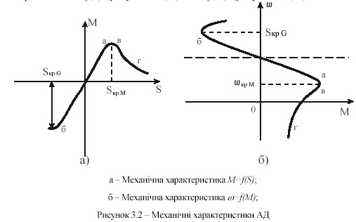
Перша ділянка аб (|S|<|Sкр|) знаходиться у межах малих (за абсолютним значенням) ковзань. Ця ділянка характеристики є лінійною. Для двигуневого режиму це робоча частина характеристики, на ній знаходиться точка номінального режиму роботи. Друга ділянка характеристики – вг являє собою криву близьку до рівнобічної гіперболи і знаходиться у межах великих ковзань (|S|>|Sкр|). Ділянка відповідає неробочій частині характеристики (режими пуску двигуна й гальмування).
Для
двигуна з фазним ротором, як вже
зазначалося, величина а
близька
до одиниці, тому з достатньою точністю
Sкр
можна
визначити з (3.5) для номінального режиму
(М=Мном;
S=Sном;
![]() =Mmax/Mном):
=Mmax/Mном):
Приблизне значення Sкр для асинхронних двигунів з фазним ротором можна знайти також і за формулою (3.6):
![]()
Для асинхронних двигунів з короткозамкненим ротором Sкр й а можна розрахувати, використовуючи рівняння (3.4) для двох характерних режимів:
пускового (М=Мном; S=1,0),
номінального (М=Мном; S=Sном).
Отриману систему рівнянь
вирішують відносно Sкр та а, тоді обчислюють М=f(S) для двигуневого режиму, спираючись на низку поточних значень ковзання S(0S1), та будують механічну характеристику: ω=f(M)
У наведених формулах використовувалось номінальне ковзання, розраховане у системі одиниць СІ за формулою.
![]() -
через кутову швидкість, (в.о.);
-
через кутову швидкість, (в.о.);
де
![]() ,
[с-1]
- синхронна кутова швидкість.
,
[с-1]
- синхронна кутова швидкість.
У практичній системі одиниць ця формула має вигляд
![]() (в.о.),
(в.о.),
де
![]() [об/хв.]-
синхронна частота обертання
[об/хв.]-
синхронна частота обертання
Зв’язок ніж синхронною швидкістю у системі одиниць СІ і у практичній системі одиниць має вигляд
![]() [1/c]
[1/c]
Частота живлення f задана, здебільшого це промислова частота 50 Гц, число пар полюсів р легко визначити з паспортних даних двигуна.