

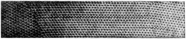
3. Grain boundaries
Figures 5a, 56 and 5c, plates 9 and 10, show typical grain boundaries for bubbles of 1.87, 0.76 and 0.30 mm. diameter respectively. The width of the disturbed area at the boundary, where the bubbles have an irregular distribution, is in general greater the smaller the bubbles. In figure 5a, which shows portions of several adjacent grains, bubbles at a boundary between two grains adhere definitely to one crystalline arrangement or the other. In figure 5с there is a marked ' Beilby layer' between the two grains. The small bubbles, as will be seen, have a greater rigidity than the large ones, and this appears to give rise to more irregularity at the interface,
Separate grains show up distinctly when photographs of polycrystalline rafts such as figures 5a to 5c, plates 9 and 10, and figures 12a to 12e, plates 14 to 16, are viewed obliquely. With suitable lighting, the floating raft of bubbles itself when viewed obliquely resembles a polished and etched metal in a remarkable way.
It often happens that some 'impurity atoms', or bubbles which are markedly larger or smaller than the average, are found in a polycrystalline raft, and when this is so a large proportion of them are situated at the grain boundaries. It would be incorrect to say that the irregular bubbles make their way to the boundaries; it is ft defect of the model that no diffusion of bubbles through the structure can take place, mutual adjustments of neighbours alone being possible. It appears that the boundaries tend to readjust themselves by the growth of one crystal at the expense of another till they pass through the irregular atoms.
4. Dislocations
When a. single crystal or polycrystalline raft is compressed, extended, or otherwise deformed it exhibits a behaviour very similar to that which has been pictured for metals subjected to strain. Up to a certain limit the model is within its elastic range. Beyond that point it yields by slip along one of the three equally inclined directions of closely packed rows. Slip takes place by the bubbles in one row moving forward over those in the next row by an amount equal to the distance between neighbours. It is very interesting to watch this process taking place. The movement is not simultaneous along the whole row but begins at one end with the appearance of a 'dislocation', where there is locally one more bubble in the rows on one side of the slip line as compared with those on the other. This dislocation then runs along the slip line from one side of the crystal to the other, the final result being a slip by one 'inter-atomic' distance. Such a process has been invoked by Orowan, by Polanyi and by Taylor to explain the small forces required to produce plastic gliding in metal structures. The theory put forward by Taylor (1934) to explain the mechanism of plastic deformation of crystals considers the mutual action and equilibrium of such dislocations. The bubbles afford a very striking picture of what has been supposed to take place in the metal. Sometimes the dislocations run along quite slowly, taking a matter of seconds to cross a crystal; stationary dislocations also are to be seen in crystals which are not homogeneously strained. They appear as short black lines, and can be seen in the series of photographs, figures 12a to 12 e, plates 14 to 16. When a polycrystalline raft is compressed, these dark lines are seen to be dashing about in all directions across the crystals.
Figures 6a, 66 and 6c, plates 10 and 11, show examples of dislocations. In figure 6a, where the diameter of the bubbles is 1.9 mm., the dislocation is very local, extending over about six bubbles. In figure 66 (diameter 0.76 mm.) it extends over twelve bubbles, and in figure 6c (diameter 0.30mm.) its influence can be traced for a length of about fifty bubbles. The greater rigidity of the small bubbles leads to longer dislocations. The study of any mass of bubbles shows, however, that there is not a standard length of dislocation for each size. The length depends upon the nature of the strain in the crystal. A boundary between two crystals with corresponding axes at approximately 30° (the maximum angle which can occur) may be regarded as a series of dislocations in alternate rows, and in this case the dislocations are very short. As the angle between the neighbouring crystals decreases, the dislocations occur at wider intervals and at the same time become longer, till one finally has single dislocations in a large body of perfect structure as shown in figures 6a, 6b and 6c.
Figure 7, plate 11, shows three parallel dislocations. If we call them positive and negative (following Taylor) they are positive, negative, positive, reading from left to right. The strip between the last two has three bubbles in excess, as can be seen by looking along the rows in a horizontal direction. Figure 8, plate 12, shows a dislocation projecting from a grain boundary, an effect often observed.
Figure 9, plate 12, shows a place where two bubbles take the place of one. Thin may be regarded as a limiting case of positive and negative dislocations on neighbouring rows, with the compressive sides of the dislocations facing each other. The contrary case would lead to a hole in the structure, one bubble being missing at the point where the dislocations met.
Фиг. 2. Идеальное расположение пузырьков. Диаметр 1,41 мм.

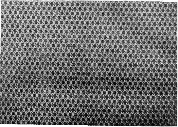
Фиг. 4. Регулярное расположение «маленьких» пузырьков. Диаметр 0,30 мм.
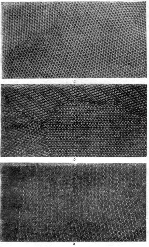
Фиг. 5. Типичные границы зерен. а — диаметр 1,87 мм; б — диаметр 0,76 мм; в — диаметр 0,30 мм.
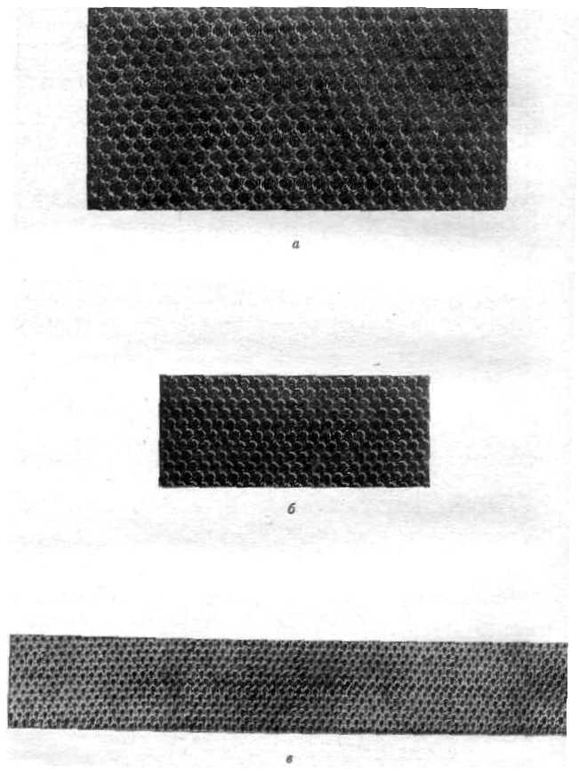
Фиг. 6. Дислокации. а —диаметр 1,9 мм; б — диаметр 0,76 мм; в — диаметр 0,30 мм.
Фиг.
7. Параллельные дислокации. Диаметр
0,76 мм.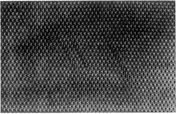
Фиг. 8. Дислокация, проектирующаяся от границ зерна.
Фиг.
9. Дислокации в соседних рядах.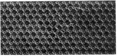
Здесь воспроизведены лишь первые четыре параграфа статьи из Proceedings of the Royal Society of London, Vol. 190, p. 474 (1947). Нумерация листов, на которых размещены рисунки, в оригинале и переводе не совпадают. Литература, приведенная в конце статьи, дана в переводе в подстрочных примечаниях.— Прим. ред.
ДИНАМИЧЕСКАЯ МОДЕЛЬ КРИСТАЛЛИЧЕСКОЙ СТРУКТУРЫ
Л. Брэгг и Дж. Най
Кристаллическая структура металла моделируется скоплением пузырьков диаметром 1 мм и меньше, плавающих на поверхности мыльного раствора. Пузырьки выдуваются из маленькой пипетки, расположенной ниже поверхности раствора; давление воздуха в пипетке постоянно, и размеры пузырьков чрезвычайно мало отличаются друг от друга. Пузырьки удерживаются вместе за счет поверхностного натяжения, выстраиваясь в один слой на поверхности или образуя трехмерную массу. Скопление может содержать сотни тысяч пузырьков и сохраняется в течение часа или более. Скопление образует структуры, которые, как предполагают, имеются в металлах, и имитируют эффекты, которые уже наблюдались, такие, как формирование границ между зернами, дислокаций и других типов дефектов, процессы скольжения, явления рекристаллизации и отжига, возникновение напряжений, связанных с «посторонними» атомами.